
Subscribe to Our Youtube Channel
Related Manuals for Leuze IGSU 14E


Summary of Contents for Leuze IGSU 14E
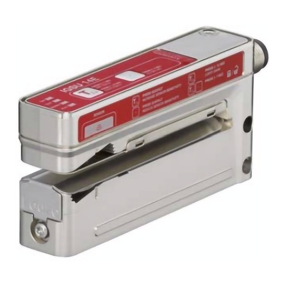
- Page 1 Ultrasonic label fork IGSU 14E Leuze electronic GmbH + Co. KG In der Braike 1 73277 Owen Tel.: +49 7021 573-0 info@leuze.com • www.leuze.com...
- Page 2 1Figure part...
- Page 3 2-7 s 7-12 s > 12 s 2-7 s > 7 s...
- Page 4 2-7 s 7-12 s...
- Page 5 > 12 s 2-7 s...
- Page 6 – < 2 s < 2 s > 7 s ≥ 20 ms ≥ 20 ms HIGH...
-
Page 8: Intended Use
Intended use The ultrasonic label forks are ultrasonic sensors for contactless detection of the gap between two consecutive labels on a carrier tape. NOTICE Observe intended use! This product is not a safety sensor and is not intended as personnel protection. - Page 9 IGSU 14E standard functions During operation the sensor is always in this function. The sensor detects label gaps with high precision and speed. This is indicated by the yellow OUT LED and the switching output. ON LED Constantly ON when operating voltage is applied. green OUT LED Indicates the switching signal.
- Page 10 easy Teach while the label tape is passing through (dynamic) During the easy Teach process, a two-point calibration is performed on the carrier and the label. NOTICE With respect to detection reliability, the easy Teach process is gener- ally to be preferred over the static teach process. Preparation: Insert label tape into the sensor.
- Page 11 Adjusting the switching behavior of the switching output (light/dark switching) Ä Press the teach button until only the green ON LED flashes. Ä Release the teach button. The green ON LED flashes for another 2 seconds and the yellow OUT LED indicates the changed switching behavior for 2 seconds: –...
- Page 12 Activate or deactivate ALC function The ALC function can be manually deactivated and activated. Ä Press the minus button (-) until the green ON LED and the yellow OUT LED flash synchronously. Ä Release the minus button (-). NOTICE The manual deactivation/activation of the ALC function is stored in non-volatile memory in the sensor.
- Page 13 Recommended settings Observation Measure Action Repeatedly press the mi- After teaching, the yellow Reduce sensitivity of the LED and the switching sensor nus button (-) briefly until output flicker if the label is (upward shift of the the sensor detects the moved through the sen- switching threshold) moving label stably and...
- Page 14 Sensor adjustment via teach input (pin 5) Teach-in To teach, a teach signal is applied to the teach input (pin 5). The duration of the teach signal (low level on the teach input) determines the teach-in function. NOTICE Before a low level is applied for teaching-in functions, a high level must be applied for at least 20 ms.
- Page 15 Locking the buttons via the teach input Manual locking of the buttons on the device is only suitable for protecting against tampering to a limited extent since locking can be canceled using the correspond- ing button combination. For this reason, it is also possible to lock the buttons via the teach input (pin 5).
Need help?
Do you have a question about the IGSU 14E and is the answer not in the manual?
Questions and answers