
Subscribe to Our Youtube Channel
Related Manuals for Leuze IGSU 14E SD


Summary of Contents for Leuze IGSU 14E SD
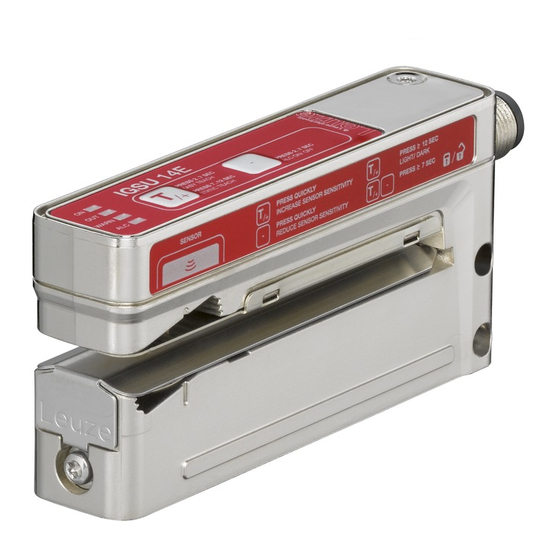
- Page 1 Ultrasonic fork for splice detection IGSU 14E SD Leuze electronic GmbH + Co. KG In der Braike 1 73277 Owen Tel.: +49 7021 573-0 info@leuze.com • www.leuze.com...
- Page 2 1Figure part 2-7 s 7-12 s...
- Page 3 > 12 s – < 2 s < 2 s > 7 s...
- Page 4 ≥ 20 ms ≥ 20 ms HIGH...
-
Page 5: Intended Use
Intended use The ultrasonic forks for splice inspection are ultrasonic sensors for the contactless detection of splices on paper, film or plastic webs. NOTICE Observe intended use! This product is not a safety sensor and is not intended as personnel protection. - Page 6 IGSU 14E SD standard functions (splice detection) During operation the sensor is always in this function. The sensor detects splices with high precision and speed. This is indicated by the yellow OUT LED and the switching output. ON LED Constantly ON when operating voltage is applied. green OUT LED Indicates the switching signal.
- Page 7 easy Teach with or without web transport Preparation: place paper, film or plastic web in the sensor. Ä Press the teach button until the green ON LED and the yellow OUT LED flash synchronously. Ä Release the teach button. ð The teaching time of approx. six seconds begins. The sensor indicates this by a more rapid synchronous flashing of the green ON LED and yellow OUT LED.
- Page 8 Setting the pulse stretching If the web speed is high and the splice width is thin, the signal on the switching output is very short when moving over a splice. – Therefore a fixed pulse stretching of 20 ms is activated in the factory set- tings.
- Page 9 easyTune – Manual fine tuning of the switching threshold With homogeneous web material, the signal on the web is greater than the signal on the splice. For the taught switching threshold, there is a high function reserve, and the sensor functions reliably.
- Page 10 Manual locking/unlocking of the buttons on the device To protect against erroneous operation, the locking of the buttons is intended to prevent a button on the device from accidentally being pressed. Accidental button actuation could unintentionally trigger the easyTune function or the teaching of the device.
- Page 11 Sensor adjustment via teach input (pin 5) Teach-in To teach, a teach signal is applied to the teach input (pin 5). The duration of the teach signal (low level on the teach input) determines the teach-in function. NOTICE Before a low level is applied for teaching-in functions, a high level must be applied for at least 20 ms.
- Page 12 Locking the buttons via the teach input Manual locking of the buttons on the device is only suitable for protecting against tampering to a limited extent since locking can be canceled using the correspond- ing button combination. For this reason, it is also possible to lock the buttons via the teach input (pin 5).
Need help?
Do you have a question about the IGSU 14E SD and is the answer not in the manual?
Questions and answers