
Related Manuals for Leuze LES 36 Series


Summary of Contents for Leuze LES 36 Series
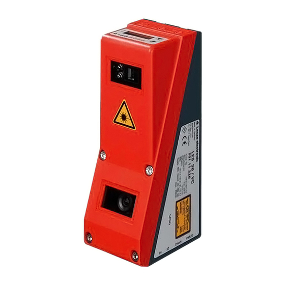
- Page 1 LES - Line Edge Sensor Light section sensors O r ig i n a l o p e r a t in g in s t r u c t io n s...
- Page 2 © 2018 Leuze electronic GmbH + Co. KG In der Braike 1 D-73277 Owen / Germany Phone: +49 7021 573-0 Fax: +49 7021 573-199 http://www.leuze.com info@leuze.com Leuze electronic LES 36...
-
Page 3: Table Of Contents
Inspection Task............26 Leuze electronic... - Page 4 Characteristic curve of analog output ..........50 Leuze electronic...
- Page 5 Apply Settings ..............76 Leuze electronic...
- Page 6 Scan number............98 Leuze electronic...
- Page 7 Description of the input data..........121 Leuze electronic...
- Page 8 Order codes of the cables for voltage supply ......... . . 136 Leuze electronic...
- Page 9 Index..........148 Leuze electronic...
-
Page 10: Leuze Electronic Les 36
Typical minimum object size LES 36HI… ....... . 19 Figure 4.1: Mechanical design of Leuze light section sensors......20 Figure 4.2: Activation input signal sequence . -
Page 11: Figures And Tables
Revision History - Firmware ......... . 145 Leuze electronic... -
Page 12: Leuze Electronic Les 36
Revision History - Configuration software ....... 146 Leuze electronic LES 36... -
Page 13: General Information
Note! The CE Declaration of Conformity for these devices can be requested from the manufacturer. The manufacturer of the product, Leuze electronic GmbH & Co. KG in D-73277 Owen, possesses a certified quality assurance system in accordance with ISO 9001. -
Page 14: Safety
Only operate the device in accordance with its intended use. Leuze electronic GmbH + Co. KG is not liable for damages caused by improper use. Read these operating instructions before commissioning the device. Knowledge of this document is required in order to use the equipment for its intended purpose. -
Page 15: Foreseeable Misuse
The device must not be tampered with and must not be changed in any way. The device must not be opened. There are no user-serviceable parts inside. Repairs must only be performed by Leuze electronic GmbH + Co. KG. Competent persons Connection, mounting, commissioning and adjustment of the device must only be carried out by competent persons. -
Page 16: Exemption Of Liability
BGV A3 (e.g. electrician foreman). In other countries, there are respective regula- tions that must be observed. Exemption of liability Leuze electronic GmbH + Co. KG is not liable in the following cases: • The device is not being used properly. • Reasonably foreseeable misuse is not taken into account. -
Page 17: Figure 2.1: Laser Apertures, Laser Warning Signs
Affix the laser information and warning signs so that they are legible without exposing the reader to the laser radiation of the device or other optical radiation. A Laser aperture B Laser warning sign C Laser information sign with laser parameters Figure 2.1: Laser apertures, laser warning signs Leuze electronic LES 36... -
Page 18: Figure 2.2: Laser Warning And Information Signs - Supplied Stick-On Labels
8.7 mW Pulse duration: 3 ms 3 ms Wavelength: 658 nm 658 nm CLASS 2M LASER PRODUCT IEC 60825-1:2007 GB7247.1-2012 Complies with 21 CFR 1040.10 Figure 2.2: Laser warning and information signs – supplied stick-on labels Leuze electronic LES 36... -
Page 19: Operating Principle
Depending on the distance of the object the laser line is projected to a different position on the CMOS planar detector as shown in Figure 3.1. By means of this position the distance of the object can be calculated. Leuze electronic LES 36... -
Page 20: Limits Of Light Section Sensors
When the object is shifted to the left the object con- tour will still be detected by the laser but the laser line does not lie within the receiver's field of view at that point, and therefore no measurement values can be detected. Figure 3.2: Occlusion Leuze electronic LES 36... -
Page 21: Possible Measure Against Laser Occlusion
In the example to the right, the left sensor detects the profile data on the left side of the product, and the right sensor the profile data on the right side. In this situation the second sensor is then cas- caded. "Cascading" on page 24. Leuze electronic LES 36... -
Page 22: Resolution
The output resolution of the measurement values on the process interface is 1/10mm with Standard-Connect, 1/100mm with HI-Connect (only with LES 36HI/VC6). Object distance in Z direction [mm] Figure 3.4: Typical minimum object size LES 36HI… Leuze electronic LES 36... -
Page 23: Device Description
The following shows a light section sensor as an example. An overview of the available types may be found in Chapter 15.1 Figure 4.1: Mechanical design of Leuze light section sensors 4.1.2 General performance characteristics • Light section sensor for width, height and position detection •... -
Page 24: Line Edge Sensor - Les
Determining width and diameter of roll goods and PROFIBUS Typical areas of application • Edge and height measurement of web material products and paper rolls • Width and height measurement of cartons • Edge and height measurement of stackable materials (e.g. chipboards) Leuze electronic LES 36... -
Page 25: Operating The Sensor
Pin 2 at X1 Output Approx. 14ms 10ms between 2 consecutive between laser pulse and laser pulses in "Free Running" Axes: p = level, t = time associated data output mode Figure 4.2: Activation input signal sequence Leuze electronic LES 36... -
Page 26: Triggering - Free Running
Trigger input Pin 5 at X1 Laser Activation input Pin 2 at X1 Output (Ethernet) Data packets, approx. 1ms Approx. 14ms Axes: p = level, t = time Figure 4.3: Trigger input signal sequence Leuze electronic LES 36... -
Page 27: Profibus Trigger
Sensor 1, or the master, can be operated in this case both triggered as well as continuously. All other sensors must be operated triggered. Cascading settings For all sensors except the last slave, the cascading output must be enabled via configuration software: Cascading Output: Enable. Leuze electronic LES 36... -
Page 28: Measurement Functions: Les
"Sequent Hits" parameter was introduced. The minimum number of measurement points set there must occur in succession in the EAW to detect a valid edge. Outliers or missing measurement points reset the counter. Leuze electronic LES 36... -
Page 29: Inspection Task
("rightmost" RX, RZ) are determined in each EAW. • EAWs usually have an absolute position. If the object position varies, an EAW can also be positioned relative to a found edge position in the previous EAW and thus tracked. Leuze electronic LES 36... -
Page 30: Definition Of Eaws And Their Analysis Results
If there are not enough successive measurement points on the edges of an EAW, the found edge positions are shifted away from the edges of the EAW (see Figure 4.7, different right edge position with different parameters for Sequent Hits). Leuze electronic LES 36... -
Page 31: Figure 4.7: Meaning Of Sequent Hits For Edge Detection
• Width of objects: W (calculated from the distance of RX and LX in the X direction). • Height difference of left and right edge: H (calculated from the distance of RZ and LZ in the Z-direction). Leuze electronic LES 36... -
Page 32: Figure 4.8: Edge Detection With Eaws
Measurement range Measurement points Left edge Right edge (coordinates LX, LZ) (coordinates RX, RZ) No object detection due to shadowing in the measure- Object ment range EAW01 Conveyor path x axis Figure 4.8: Edge detection with EAWs Leuze electronic LES 36... -
Page 33: Relative Window Positioning
EAW01. This window now tracks all position changes of the object edge to be measured, both in the X-direction and Z-direction. Note! The evaluation functions are defined using LESsoft (see Chapter 9.4). Leuze electronic LES 36... -
Page 34: Object Detection
X direction has nearly twice as many hit points as it does at a far distance (e.g, 600mm). If the object distance is the same, the number of hit points remains nearly constant. Leuze electronic LES 36... -
Page 35: Application Examples For Eaws
Figure 4.10: Application example: web-edge measurement In the example shown above, the edge position of web material is to be determined. Analysis is performed in Edge Analysis Window EAW01. The edge coordinates for edge LX, LZ are determined in EAW01. Leuze electronic LES 36... -
Page 36: Application Example: Height And Width Measurement Of A Cubic Object
The object is on a conveyor line. The width is measured in edge analysis window EAW01; the height is measured in EAW03. The following measurement values are obtained: • in EAW01: Object Width W = LX1 - RX1 • in EAW03: Object Height H = RZ3 - LZ3 Leuze electronic LES 36... -
Page 37: Analysis Window (Aw)
X direction has nearly twice as many hit points as it does at a far distance (e.g, 600mm). If the object distance is the same, the number of hit points remains nearly constant. Leuze electronic LES 36... -
Page 38: Installation And Mounting
Save the original packaging for later storage or shipping. If you have any questions concerning your shipment, please contact your supplier or your local Leuze electronic sales office. Observe the applicable local regulations when disposing of the packaging materials. -
Page 39: Mounting The Les
• Using a BT 56 mounting device on the two fastening grooves. • Using a BT 59 mounting device on the two fastening grooves. Dovetail fastening grooves M4 threaded holes Figure 5.2: Fastening options Figure 5.3: Mounting example LES Leuze electronic LES 36... -
Page 40: Bt 56 Mounting Device
LES Clamp profile for mounting to round or oval pipes Ø 16 … 20mm all dimensions in mm A Rod holder, turnable 360° B Rods Ø 16 … 20mm Figure 5.4: BT 56 mounting device Leuze electronic LES 36... -
Page 41: Bt 59 Mounting Device
A Holder, turnable 360° B ITEM joint, angle adjustable ±90° C M8x16 screw cylinder, M8 serrated washer, M8 sliding block, connectors for ITEM pro- file (2x) Figure 5.5: BT 59 mounting device Leuze electronic LES 36... -
Page 42: Device Arrangement
The general principle is that the Light section sensor should be aligned so that the back of the sensor is aligned parallel to the conveying belt or measuring plane. Rotation along the Y-axis is not desirable. The Figure 5.6 illustrates the problem: Leuze electronic LES 36... -
Page 43: Attach Laser Warning Sign
In doing so, avoid leaving fingerprints on the optics cover of the LES. Attention! Do not use aggressive cleaning agents such as thinner or acetone for cleaning the device. Leuze electronic LES 36... -
Page 44: Electrical Connection
An overview of the available types may be found in Chapter 15.1 Figure 6.2: Connections of the LES The pin assignment of X1 and X2 is identical for all Light section sensors; X3 and X4 differ depending on device type. Leuze electronic LES 36... -
Page 45: Safety Notices
Degree of protection IP 67 is achieved only if the connectors and caps are screwed into place! The connectors used must be equipped with O-ring seals. Therefore, preferably, please use the ready-made cables by Leuze electronic. Leuze electronic LES 36... -
Page 46: Shielding And Line Lengths
…) as far from the sensor cables as possible (distance > 30cm). Avoid laying power and sensor cables parallel to one another. Cable crossings should be laid as perpendicular as possible. Lay cables close to grounded metal surfaces: This measure reduces interference coupling in the cables. Leuze electronic LES 36... -
Page 47: General Shielding Information
Devices produced after April 2011 are All devices can also be connected equipped with an additional ground- to ground potential at the M4 ing terminal. threaded hole on the dovetail. Figure 6.3: Connecting the ground potential to the light section sensor Leuze electronic LES 36... -
Page 48: Connecting The Cable Shielding In The Switch Cabinet
• Mounting rails must be well grounded Comment: Depicted shield components from Wago, series 790 ...: - 790-108 Shield clamping bracket 11 mm - 790-112 Carrier with grounding foot for TS35 Figure 6.5: Connecting the cable shielding to the PLC Leuze electronic LES 36... -
Page 49: Connecting
The trigger input is used for synchronizing the measurement with the process and for synchronizing cascaded sensors. Further information can be found in Chapter 4.2.3 and Chapter 4.2.4. The internal equivalent circuit is shown in Figure 6.6. Leuze electronic LES 36... -
Page 50: Cascading Output Outcas
HOST / BUS IN cable assignments on RJ-45 Notice for connecting the Ethernet interface! Ensure adequate shielding. The entire interconnection cable must be shielded and earthed. The Rx+/Rx- and Tx+/Tx- wires must be stranded in pairs. Use CAT 5 cables for the connection. Leuze electronic LES 36... -
Page 51: Connection X3 - Switching Inputs/Outputs (Les 36
0, "001" inspection task 1, etc. The changeover time between two inspection tasks is < 100ms Note! The Inspection Tasks 8-15 can be switched via LRSsoft, PROFIBUS or Ethernet. The setting via Ethernet overwrites the inspection task set via input InSel1-3. Leuze electronic LES 36... -
Page 52: Connection X4 - Profibus Dp (Les 36
For the connection, we recommend our ready-made PROFIBUS cables (see chapter 15.2.5 "Connection accessories / ready-made cables for X4 (only LES 36…/PB)") For the bus termination, we recommend our PROFIBUS terminating resistor (see chapter 15.2.5 "Connection accessories / ready-made cables for X4 (only LES 36…/PB)") Leuze electronic LES 36... -
Page 53: Connection X4 - Voltage/Current Output (Les 36
(the minimum adjustment range is 10mm). The characteristic output curve can be configured as rising or falling. For this purpose, both distance values Position Min. Val. and Position Max. Val. for the minimum and maximum analog output value are set accordingly, see Figure 6.8. Leuze electronic LES 36... -
Page 54: Figure 6.8: Response Of Analog Output Les
+200 … +800mm +200 … +800mm Height difference 0 … 600mm 0 … 400mm Width 0 … 600mm 0 … 140mm Note! Valid Z-values are output 10mm above and beyond the max. measurement range: 190 … 810mm. Leuze electronic LES 36... -
Page 55: Display And Control Panel
Ethernet connection established Flashing Ethernet data transmission active No Ethernet connection Table 7.1: LED function indicator 7.1.2 Control buttons The LES is operated using the and buttons, which are located next to the OLED display. Leuze electronic LES 36... -
Page 56: Indicators In The Display
Definition of the displayed measurement value: • For analog sensors, the measurement value assigned to the analog output is displayed in mm. • For sensors with PROFIBUS, the measurement value assigned under Edge 1 - Pro- fibus Inputs 1 is displayed. Leuze electronic LES 36... -
Page 57: Command Mode
OLED display has one line. Command Mode appears on the first line of the display. Command Mode Note! If errors occur during operation, these are shown on the display. Notes can be found in Chapter 12.3. Leuze electronic LES 36... -
Page 58: Menu Description
Error Handling Slave Address PROFIBUS DP slave address Ethernet Slave Address Setting for the PROFIBUS DP slave address 126 Ethernet Ethernet interface parameters Display IP Address IP address of the sensor 192.168.060.003 Table 7.2: Menu structure Leuze electronic LES 36... - Page 59 Execute reset with subsequent confirma- Execute tion prompt Return to menu level 1 Reset to Factory Info Device Information menu item Menu Exit Part no. Leuze part number of the sensor 50115418 Table 7.2: Menu structure Leuze electronic LES 36...
- Page 60 Level 1 Level 2 Level 3 Level 4 Explanation / Notes Default Serial No. Sensor serial number 01408004336 Ext. Info Leuze-internal information K000 Software Software version of the sensor V01.50 Return to menu level 1 Part no. Menu Exit Exit menu and return to measure mode Select Insp.
-
Page 61: Operation/Navigation
192.168.001.111 rejects the new value(in this example, the factory setting 192.168.060.003 remains saved) Editing selection parameters displays the next option for Display (Off). Display returns to the next-higher menu level and retains On. Leuze electronic LES 36... -
Page 62: Reset To Factory Settings
2s; the LES then returns to measure mode. You can select the resetting to factory settings also via LESsoft. In the Configuration menu select the entry Reset to Factory Settings. Leuze electronic LES 36... -
Page 63: Commissioning And Configuration
Table 8.1: Address allocation in the Ethernet Instead of xxx you can now allocate any numbers between 000 and 255 to your PC, but NOT THE SAME numbers as contained in the address of the LES. Leuze electronic LES 36... -
Page 64: Setting The Default Gateway
The PC first tries to establish a network connection via the automatic configuration. This takes a few seconds, after which the alternate configuration, which you just set, is activated. The PC can now communicate with the LES. Information about configuring with the LESsoft can be found in Chapter 9. Leuze electronic LES 36... -
Page 65: Commissioning
If several sensors are to be activated, all sensors as well as the control must receive different IP addresses on the same subnet. For all sensors different ports must be configured in Sensor area as well as in the Client/PC area. Leuze electronic LES 36... -
Page 66: Lessoft Configuration Software
You can find it for the respective product in the Downloads tab under Configuration software. Note! Copy the downloaded file into a suitable folder on your hard drive. Administrator privileges are necessary for this purpose. - Page 67 LESsoft configuration software Leuze electronic LES 36...
- Page 68 LESsoft configuration software Depending on the configuration of your Windows system, the dialog shown below may then appear (missing component VCREDIST_X86). Click on Install. Two additional installation windows will appear, which do not require any further entry. Leuze electronic LES 36...
- Page 69 After some time (up to several minutes depending on the system configuration) the start screen of the MCR installer will appear. Click on Next. The window for entering user data appears. Enter your name and the company name and then click on Next. Leuze electronic LES 36...
- Page 70 Click on Next and in the next window click on Install. The installation will start and a status window will be displayed. This can again take several minutes. Following successful MCR installation, the InstallShield Wizard Completed window appears. Click on Finish to end the MCR-installation. Leuze electronic LES 36...
- Page 71 Keep the default folder in this case as well and click on Next. Upon completion of the installation process, the window shown above appears. The installation routine added a new Leuze electronic program group in your Start menu that contains the installed programs LESsoft/LPSsoft/LRSsoft.
-
Page 72: Possible Error Message
Then click on OK and close also all further windows using OK. Shut Windows down, restart Windows and then start LESsoft by double-clicking on it. Now the start screen of LESsoft appears, as described in Chapter 9.3. Leuze electronic LES 36... -
Page 73: Device List Update
You do, however, have the possibility to install a device list to implement new device models in the software. This can be downloaded from www.leuze.com in the download area for your device under "Device list". Install this and restart the software. The previously unknown sensor is then recognized. -
Page 74: Starting Lessoft/Communication Tab
As a result LESsoft establishes a connection and displays the currently measured 2D profile. In the status line at the bottom left of the display you will now find Online highlighted in green instead of Offline highlighted in red. Leuze electronic LES 36... - Page 75 • Scan number (Profile Number) • Encoder value dependent on the sensor type (Encoder Value) • Connected sensor type • Analog output status (Analog Output) Note! Once the LESsoft has established a connection to the LES, the laser beam flashes. Leuze electronic LES 36...
-
Page 76: Profibus Settings (Only Les 36/Pb And Les 36Hi/Pb)
After changing the PROFIBUS slave address via the display or LESsoft, a power-on reset must be performed in order to permanently accept the address. For the changed settings to take effect, they must be transferred to the sensor! Leuze electronic LES 36... -
Page 77: Parameter Settings/Parameters Tab
By removing the tick in the Enable External Inspection Task Selection check box, the inspection task cannot be changed via the process interface while configuration is being performed. After configuring with LESsoft and before transmitting the settings to the Leuze electronic LES 36... -
Page 78: Operation Mode
Select an exposure setting that displays a continuous line around the object contour. Then try to achieve a line on a flat surface that is as continuous as possible. Leuze electronic LES 36... -
Page 79: Field Of View
How evaluation of the measurements functions with EAWs and AWs is described in Chapter 4.3 and Chapter 4.4. Click the Edit Analysis Windows button to open the table for defining the analysis windows. Leuze electronic LES 36... -
Page 80: Using The Mouse
The font of the Accept Analysis Window Rectangle button turns black after size and/ or position of the analysis window have been changed using the mouse. You have to click the button in order to accept the values in the 2D representation. Leuze electronic LES 36... -
Page 81: Keyboard Input
Status column is red (not ok). If the EAW is not activated, the status is gray. If not enough measurement points occurred in succession in an EAW, edge detection and object measurement within this EAW is not possible. Leuze electronic LES 36... -
Page 82: Analysis Window Definitions
The further processing and combination of results from object detection occurs by pressing the Edit Logical Combinations button. Note! The changed settings must be transferred to the sensor with Apply Settings. Leuze electronic LES 36... -
Page 83: Edit Logical Combinations
• Red state = edge detection and object detection not ok Note! For sensors with analog output, a valid measurement value transmission for edges only occurs at the analog output if the Edge State is ok. Leuze electronic LES 36... -
Page 84: Object Point/Eaw State (Result Of Edge Detection)
If the check box is selected, the left edge position is displayed in the 2D view with a green coordinate cross, the right edge position with a blue coordinate cross. Figure 9.6: Display of the edge positions (green and blue) in the 2D display Leuze electronic LES 36... -
Page 85: X, Width (X), Z, Height (Z)
EAW via the PROFIBUS. In the Profibus Inputs 1 and Profibus Inputs 2 fields, you can configure which measurement values these are for up to four edge analyses. Note! The changed settings must be transferred to the sensor with Apply Settings. Leuze electronic LES 36... -
Page 86: Application Example 1: Web Edge Measurement
The ascertained position of the right edge is -9.6mm (column Edge1 -> Right Most -> line X). The distance from the edge to the sensor is 366.6mm (column Edge1 -> Right Most ->line Z). Figure 9.7: Application example 1: web edge measurement Leuze electronic LES 36... -
Page 87: Application Example 2: Height And Width Monitoring Of Cubic Objects
49.6mm (column Edge2 -> line Height (Z)). All measurement results are displayed in the window to the right of the 2D view. Figure 9.8: Application example 2: height and width monitoring of cubic objects Leuze electronic LES 36... -
Page 88: Additional Object Detection With Les Sensors
= 3 -> response time 3 x 10ms = 30ms). Interfering signals of individual scans are suppressed. If an analysis depth = 1 (factory stetting beginning with firmware version 01.25) is selected, the response time is 10ms. Leuze electronic LES 36... -
Page 89: Aw Logic Analysis Depth (Result Of Object Detection)
• Green state = ok • Red state = not ok Note! A display appears only if object detection was activated in an EAW/AW. Note! The changed settings must be transferred to the sensor with Apply Settings. Leuze electronic LES 36... -
Page 90: Application Example 3: Width Monitoring Of Cubic Objects With Object Detection
Tables window, the additional object detection is activated by selecting + under EAW1. All results are green (ok). The ascertained width of the carton is 49.2mm (column Edge1 - > line Width (X)). Figure 9.9: Application example 3.1: width monitoring of cubic objects with object detection Leuze electronic LES 36... -
Page 91: Detection
Edge Status is ok (see Page 80). In the case of sensors with digital switching outputs at X3 (LES 36/VC6, LES 36 HI/VC6), the status of Edge 1 to 4 is signaled at outputs Out1 to Out4 (HIGH active). Leuze electronic LES 36... -
Page 92: Standard Tab - Single Shot Mode Panel
Selection to configure whether or not the inspection tasks 0 … 15 can be selected via PROFIBUS. Note! If Enable External Inspection Task Selection is ticked, the inspection task can only be selected via PROFIBUS. In this case, the drop-down menu under Inspection Task Selection has no function. Leuze electronic LES 36... -
Page 93: Analog Output Tab - Configuring The Analog Output (Only Les 36
- LX = Left edge X-coordinate - LZ = Left edge Z-coordinate - RX = Right edge X-coordinate - RZ = Right edge Z-coordinate • Width of objects: W • Height difference of left and right edge: H Leuze electronic LES 36... -
Page 94: Mm For Min. Val
Measurement value in mm for the upper range limit of the voltage or current output (10V/ 20mA) Note! The minimum adjustable range between the upper and lower range limit of the analog output is 10mm. Note! The changed settings must be transferred to the sensor with Apply Settings. Leuze electronic LES 36... -
Page 95: Menu Commands
LES and displays them in the software. • Transmit to Sensor permanently stores all parameter settings of all defined inspection tasks from the configuration software in the LES. • Reset to factory settings resets the LES to factory settings. Leuze electronic LES 36... -
Page 96: Zoom And Pan/Toolbar
Display and, if necessary, enlarge 2D view of the detection range in the Parameters tab. Standard tab - Task Parameters panel: define required (E)AWs with mouse or keyboard in the Analysis Windows Definitions window (Edit Analysis Windows but- Leuze electronic LES 36... - Page 97 Permanently transfer the configuration including all inspection tasks to the sensor with Transmit to Sensor. Where applicable: save the configuration to data carrier with Save As… Finally, disconnect the connection to the sensor: click on the button Disconnect from sensor: Leuze electronic LES 36...
-
Page 98: Integrating The Les In The Process Control (Ethernet)
LES. In the transaction number of the answer from LES there is then also 0x4E43 (byte sequence 0x43, 0x4E). The LES sends data as "little endian", i.e., first the low byte and then the high byte. Leuze electronic LES 36... -
Page 99: Protocol Structure
The packet number serves internal maintenance purposes of the manufacturer. 10.2.3 Transaction number In measure mode, 0x0000 is always displayed here. In command mode, the command acknowledgment of the sensor contains the command number of the command that is answered. Leuze electronic LES 36... -
Page 100: 10.2.4 Status
0x00000000. The 4 bytes in Encoder High and Encoder Low specify the encoder counter value for light section sensors with encoder interface. The maximum value is 0xFFFF FFFF. Beyond that an overflow to 0x0000 0000 occurs. Leuze electronic LES 36... -
Page 101: 10.2.6 Scan Number
Left edge X-value LX in EAW1 65…66 Left edge Z-value LZ in EAW1 67…68 Right edge X-value RX in EAW1 69…70 Right edge Z-value RZ in EAW1 71…72 Width W in EAW1 73…74 Height H in EAW1 Leuze electronic LES 36... - Page 102 Right edge X-value RX in EAW4 117…118 Right edge Z-value RZ in EAW4 119…120 Width W in EAW4 121…122 Height H in EAW4 123…180 - The remaining user data are used for internal maintenance purposes of the manufacturer. Unit: 1/10mm (0.1mm) Leuze electronic LES 36...
-
Page 103: Ethernet Commands
The response of the LES also corresponds to the "little-endian" standard. For further information, see the note in Chapter 10.2. All other commands are acknowledged with 'Not Ack'=0x414E; the command is not processed. Additional commands are available in command mode. Leuze electronic LES 36... -
Page 104: 10.3.1 Elementary Commands
Detailed info on possible sensor states see chapter 10.2.4 "Status". You can determine whether the sensor is in menu mode with a quick glance at the display. Menu mode can be ended with the Exit menu item. Leuze electronic LES 36... -
Page 105: 10.3.2 Commands In Command Mode
0x006F Get Single Inspection Task 0x0070 Parameter is output 9…20 Parameter 0x414E The transmitted command was Outputs individual parameters of not processed. the active inspection task Table 10.3: Sensor control commands Leuze electronic LES 36... -
Page 106: Explanation Of User Data In Command Mode (Command Parameters)
The LES responds to sensor control command 0x0049 with 0x004A and one word of user data: Byte High-Byte LSB MSB Low-Byte LSB Meaning of the bits 31…32 - N4 N3 N2 N1 Number of the configured inspection task (0 = Task0 … 15 = Task 15) Leuze electronic LES 36... -
Page 107: Set Scan Number
Successively switch all slaves (sensor 2, 3, …) to command mode and set the same scan number for each individual slave that you set previously under item 2 for the mas- ter. Switch the slaves back to measure mode. Switch the master to measure mode. Leuze electronic LES 36... -
Page 108: Set Single User Parameter
If SF=1, the duration of the transmission pause is retained even following a restart of the LES. Note! If the transfer of X-coordinates is switched off in measure mode, no visualization of mea- surement data can be performed in the 2D- and 3D-views in LESsoft. Leuze electronic LES 36... - Page 109 If SF=0, the setting for the median filter is only temporary. If SF=1, the setting for the median filter is retained even after a restart of the LES. If MF=0, the median filter is deactivated. If MF=1, the median filter is activated. Leuze electronic LES 36...
-
Page 110: Get Single User Parameter
High-Byte LSB MSB Low-Byte LSB Meaning of the bits 31…32 - P4 P3 P2 P1 Duration of the transmission pause between the Z- and X-data packets in 0.1ms increments (0 = 0.1ms … 9 = 1.0ms) Leuze electronic LES 36... -
Page 111: Set Single Inspection Task Parameter
• Detection range of the LPS (Field of View). Byte High-Byte LSB MSB Low-Byte LSB Meaning of the bits 31…32 SF = SaveFlag 33…34 Parameter ID for parameter selection 35…58 Parameter value[s] dependent on parameter ID Leuze electronic LES 36... - Page 112 LES 36HI/VC6, LES 36HI/PB: 1950…6100; LES 36/VC6, LES 36/PB: 1900…8100 (unit in 1/10mm) Sensor response: Command number Meaning Number of user data words 0x4141 "Ack": the command has been successfully executed. 0x414E "Not Ack": the command has not been executed. Leuze electronic LES 36...
-
Page 113: Get Single Inspection Task Parameter
Lower limit of parameter value (HighWord) 39…40 Lower limit of parameter value (LowWord) 41…42 Upper limit of parameter value (HighWord) 43…44 Upper limit of parameter value (LowWord) 45…46 No meaning 47…70 Parameter value(s) of accessed parameter ID Leuze electronic LES 36... -
Page 114: 10.3.4 Commands In Measure Mode
Activation Input Mode to 0x414E The transmitted command was Regard. not processed. A connection to the sensor must exist before the command can be used. Table 10.4: Commands in measure mode Leuze electronic LES 36... -
Page 115: Explanation Of User Data In Measure Mode (Command Parameters)
For sensor control command 0x4541, one word of user data is transmitted to the sensor: Byte High-Byte LSB MSB Low-Byte LSB Meaning of the bits 31…32 EA = Ethernet Activation Flag EA=0 switches off measurement operation, EA=1 switches on measurement operation. Leuze electronic LES 36... -
Page 116: Working With The Protocol
0xFFFF 0xFFFF 0x0000 0x004B 0x0000 0x0000 0x0000 0x0000 0x0000 0x0000 0x0000 0x0000 0x0000 0x0000 0x0002 0x000F 0x0001 LES to PC (command executed): 0xFFFF 0xFFFF 0x0000 0x4141 0x0000 0x0000 0x0000 0x004B 0x0000 0x0000 0x0000 0x0000 0x0000 0x0000 0x0000 Leuze electronic LES 36... -
Page 117: Operation With Lxs_Lib.dll
The LxS_Lib.dll is a .NET 2.0-compatible collection of functions which considerably facili- tates the integration of all Leuze light section sensors (LPS, LRS and LES) into PC environ- ments. The LxS_Lib.dll can be used in a variety of programming languages, such as C#, Visual Basic, etc. -
Page 118: Integration Of The Les 36
• Output of the state of the edge detection AND object detection (logical AND combi- nation). • Transmission of scan number, sensor state and of the current inspection task. • Selection of up to 16 inspection tasks. • Activation and trigger via PROFIBUS. Leuze electronic LES 36... -
Page 119: Profibus Address Assignment
55. The set address can also be queried by the user with no additional tools. Note! After changing the PROFIBUS slave address via LESsoft or with the display/key pad, a power-on reset must be performed in order to permanently accept the address. Leuze electronic LES 36... -
Page 120: General Information About The Gsd File
If these values are not changed by the user, the device operates with the default setting set by Leuze electronic on delivery. Please refer to the following module descriptions for the default settings of the device. -
Page 121: Overview Of The Gsd Modules
Activation (=1) or deactivation (=0) of the sensor uInspTask IT_b3 IT_b2 IT_b1 IT_b0 0 … 15 Inspection task of PROFIBUS master and save flag (B7) Table 11.1: PROFIBUS - Overview of output data (from viewing position of control) Leuze electronic LES 36... -
Page 122: Input Data (From Viewing Position Of Control)
OP_b4 OP_b3 OP_b2 OP_b1 OP_b0 wEdgeAW4Data2 (HighByte) sign OP_b14 OP_b13 OP_b12 OP_b11 OP_b10 OP_b9 OP_b8 -32768… Signed measurement value 2 +32767 in Edge Analysis Window EAW4 wEdgeAW4Data2 (LowByte) OP_b7 OP_b6 OP_b5 OP_b4 OP_b3 OP_b2 OP_b1 OP_b0 Leuze electronic LES 36... -
Page 123: Description Of The Output Data
After configuring, the check box for this parameter must be selected again before the con- figuration is transmitted to the sensor by means of Transmit Configuration To Sensor. Otherwise, inspection tasks can no longer be selected via PROFIBUS! Leuze electronic LES 36... -
Page 124: Description Of The Input Data
State of the edge detection (Edge State) in EAW1: 0 = not ok (red), 1 = ok (green) IT_b3 IT_b2 Number of the currently set inspection task. Value range 0 … 15 IT_b1 IT_b0 Table 11.2: Input data byte uSensorInfo Leuze electronic LES 36... -
Page 125: Sensor State
State of the object detection for EAW2: 0 = not detected or not activated, 1 = detected EAW1 State of the object detection for EAW1: 0 = not detected or not activated, 1 = detected Table 11.5: Input data byte uResultAWs Leuze electronic LES 36... -
Page 126: Measurement Value 1 In Edge Analysis Window Eaw1
Measurement value 1 in Edge Analysis Window EAW3 (wEdgeAW3Data1) These are signed, 16-bit measurement values (for information on configuration, see "Profibus Inputs 1 , Profibus Inputs 2" on page 82). Note! Description see "Measurement value 1 in Edge Analysis Window EAW1" on page 123. Leuze electronic LES 36... -
Page 127: 11.6.3 Module M3
Measurement value 2 in Edge Analysis Window EAW4 (wEdgeAW4Data2) These are signed, 16-bit measurement values (for information on configuration, see "Profibus Inputs 1 , Profibus Inputs 2" on page 82). Note! Description see "Measurement value 1 in Edge Analysis Window EAW1" on page 123. Leuze electronic LES 36... -
Page 128: Diagnostics And Troubleshooting
Check settings of the Ethernet interface. Connect sen- sor to control Sensor not activated Activate sensor via PIN 2 on X1. Switch off activation input. See "Activation" on page 75. Table 12.1: General causes of errors Leuze electronic LES 36... -
Page 129: Interface Error
Using ping command check whether the sensor LES / control responds. If so, check port assignment to LES and control. The set ports must match. Firewall blocks ports Switch off firewall temporarily and repeat connection test. Table 12.2: Interface error Leuze electronic LES 36... -
Page 130: Error Messages In Display (Starting From Firmware V01.40)
Table 12.3: Error messages in display Note! If deviating error messages occur, contact your Leuze distributor or service organization. Please disconnect the sensor from the supply voltage and eliminate the cause of the error. If a short-circuit occurs on the output, the following is displayed: Output Overload Reset ->... - Page 131 Street / no.: ZIP code / City: Country: Have the following information ready for the service department: - File: LESsoft.log (located in the installation directory of LESsoft) Leuze Service fax number: +49 7021 573 - 199 Leuze Service e-mail: service.erkennen@leuze.de Leuze electronic...
-
Page 132: Maintenance
Contact your Leuze distributor or service organization should repairs be required. The addresses can be found on the inside of the cover and on the back. Note! When sending Light section sensors to Leuze electronic for repair, please provide an accu- rate description of the error. 13.3... -
Page 133: Technical Data
3 (selection of inspection task) on X3 (LES 36/VC6 and LES 36HI/VC6) (U Signal voltage high/low -2V)/ 2V Analog output (LES 36/VC6, LES 36HI/VC6) 2k Analog output Voltage 1 … 10V, R 500 Current 4 … 20mA, R Leuze electronic LES 36... - Page 134 Number of detection fields: up to 16 with logic operation option Number of inspection tasks: up to 16 (8 of these can be activated via inputs) 1=transient protection, 2=polarity reversal protection, 3=short circuit protection for all out- puts, requires external protective circuit for inductive loads Leuze electronic LES 36...
-
Page 135: Typical Measurement Range
Technical data 14.2 Typical measurement range -300 X = line length -225 -150 Measurement range +150 +225 +300 Figure 14.1: Typical measurement range LES 36 -100 Measurement range z-axis +100 Figure 14.2: Typical measurement range LES 36HI Leuze electronic LES 36... -
Page 136: Dimensioned Drawing
OLED display and membrane keyboard M4 thread, 4.5 deep Holder for mounting system BT 56 / BT 59 Zero point and orientation of the coordinate system for measurement data 4mm bore hole in transmitter axis Figure 14.3: LES dimensioned drawing Leuze electronic LES 36... -
Page 137: Type Overview And Accessories
3 switching inputs for selection of the inspection task, model with plastic screen LRS 36/PB Line profile sensor for product detection (also multi-track), 50111332 detection range 200 … 800mm, line length 600mm, Ethernet interface, PROFIBUS DP Table 15.2: LRS type overview Leuze electronic LES 36... -
Page 138: 15.1.3 Les
200 … 600mm, line length 140mm, Ethernet interface, analog current or voltage output, 4 switching outputs for detection information, 3 switching inputs for selection of the inspection task, plastic screen Table 15.3: LES type overview Leuze electronic LES 36... -
Page 139: Accessories
KD S-M12-8A-P1-050 Cable length 5m 50135128 KD S-M12-8A-P1-100 Cable length 10m 50135129 KD S-M12-8A-P1-150 Cable length 15m 50135130 KD S-M12-8A-P1-250 Cable length 25m 50135131 KD S-M12-8A-P1-500 Cable length 50m 50135132 Table 15.6: X1 cables for the LES Leuze electronic LES 36... -
Page 140: 15.2.3 Accessories For Ethernet Interface X2
KSS ET-M12-4A-RJ45-A-P7-020 Cable length 2m 50135080 KSS ET-M12-4A-RJ45-A-P7-050 Cable length 5m 50135081 KSS ET-M12-4A-RJ45-A-P7-100 Cable length 10m 50135082 KSS ET-M12-4A-RJ45-A-P7-150 Cable length 15m 50135083 KSS ET-M12-4A-RJ45-A-P7-300 Cable length 30m 50135084 Table 15.10: Ethernet connection cables M12 connector/RJ-45 Leuze electronic LES 36... -
Page 141: Ready-Made Cables With M12 Connector/M12 Connector
Connectors Type designation Description Part no. D-ET1 RJ45 connector for user-configuration 50108991 KDS ET M12 / RJ 45 W - 4P Converter from M12, D-coded, to RJ 45 socket 50109832 Table 15.13: Connectors for the LES Leuze electronic LES 36... -
Page 142: Ccessories - Ready-Made Cables For X3 (Only Les 36
Cable length 2m 50135138 KS S-M12-8A-P1-050 Cable length 5m 50135139 KS S-M12-8A-P1-100 Cable length 10m 50135140 KS S-M12-8A-P1-150 Cable length 15m 50135141 KS S-M12-8A-P1-300 Cable length 30m 50135142 Table 15.15: X3 cables for the LES 36…/VC6 Leuze electronic LES 36... -
Page 143: Connection Accessories / Ready-Made Cables For X4 (Only Les 36
Part no. Terminator plug for PROFIBUS bus termination TS 02-4-SA M12 terminating resistor for PROFIBUS 50038539 PROFIBUS T-connector KDS BUS OUT M12-T-5P M12 T-connector for BUS OUT 50109834 Table 15.17: PROFIBUS connection accessories for the LES 36…/PB Leuze electronic LES 36... -
Page 144: Order Code Of Profibus Connection Cables For X4
KDS PB-M12-4A-M12-4A-P3-150 M12 connector + M12 socket for PROFIBUS, axial connectors, 50135256 cable length 15m KDS PB-M12-4A-M12-4A-P3-300 M12 connector + M12 socket for PROFIBUS, axial connectors, 50135257 cable length 30m Table 15.18: PROFIBUS cables for LES 36…/PB Leuze electronic LES 36... -
Page 145: Connection Accessories / Ready-Made Cables For X4 (Only Les 36
M12 connector for X4, axial connector, open cable end, 50101941 shielded, UL, 3m cable length KB 008-10000 A-S M12 connector for X4, axial connector, open cable end, 50102971 shielded, UL, 10m cable length Table 15.20: Connection cables for LES 36/VC6, LES 36HI/VC6 Leuze electronic LES 36... -
Page 146: 15.2.7 Configuration Software
Note! The current version of the configuration software can be found on the Leuze website www.leuze.com. To do this, enter your part number in the Search field. You can find the software in the Downloads tab for your device. 15.2.8 Configuration memory... -
Page 147: Appendix
Triggered series connection of several sensors. A master sensor takes over the control (synchronization) of up to 9 slaves. Measurement time Time between two individual measurements. Object Medium to be detected by sensor. Offline LESsoft is operated without sensor Online LESsoft is operated with sensor Leuze electronic LES 36... -
Page 148: Revision History / Feature List
Beginning Supports Additional device types LES 36/ LxSsoft V1.40 (LPSsoft V1.33, with V01.30 LES 36 PB with PROFIBUS and LES 36/ LESsoft V1.10, LRSsoft V1.20) VC with analog output Table 16.1: Revision History - Firmware Leuze electronic LES 36... -
Page 149: 16.2.2 Configuration Software
LxSsoft V1.30 (LPSsoft V1.30, Support of the other LRS 36/PB Configuration of PROFIBUS settings and LRSsoft V1.20) device types with PROFIBUS LRS 36/PB Table 16.2: Revision History - Configuration software Leuze electronic LES 36... - Page 150 The device list can be updated by means LESsoft V2.60, LRSsoft V2.60) new device models of an update without needing to install a new software version (see Chapter 9.2.2) Table 16.2: Revision History - Configuration software Leuze electronic LES 36...
-
Page 151: Index
Electrical connection Mounting location Electrical data Mutual interference Encoder count Environment variable Environmental data Name plate Error limits Error message Ethernet cable assignment Ethernet connection Occlusion Ethernet interface OLED display Exposure duration Optical data Exposure setting Leuze electronic LES 36... - Page 152 Measurement frequency 121 Module Output data Outputs Parameter Slave Receiver occlusion Receiving optics Repair Resolution Rod mounting Servicing Shielding System requirements System variable Termination Time behavior Triangulation principle Trigger input Trigger time Trouble shooting Type overview Leuze electronic LES 36...
Need help?
Do you have a question about the LES 36 Series and is the answer not in the manual?
Questions and answers