
Related Manuals for Leuze LRS


Summary of Contents for Leuze LRS
- Page 1 LRS - Line Range Sensor Light Section Sensors T E C H N I C A L D E S C R I P T I O N...
- Page 2 © 2013 Leuze electronic GmbH + Co. KG In der Braike 1 D-73277 Owen / Germany Phone: +49 7021 573-0 Fax: +49 7021 573-199 http://www.leuze.com info@leuze.de Technical description LRS Leuze electronic...
-
Page 3: Table Of Contents
Detection functions LRS ........ - Page 4 6.3.4 Connection X4 - PROFIBUS DP (only LRS 36/PB) ......43 Display and control panel .
- Page 5 PROFIBUS settings (only LRS 36/PB) ........
- Page 6 Additional support when integrating sensors ....... . . 91 Integration of the LRS 36/PB in the PROFIBUS ....92 11.1...
- Page 7 Repacking ..............106 Leuze electronic Technical description LRS...
- Page 8 15.2.4 Accessories ready-made cables for X3 (only LRS 36/6) ......115 Contact assignment for X3 connection cables ......... . 115 Order code of X3 connection cables .
-
Page 9: Figures And Tables
Figure 3.3: Typical minimum object size LRS 36…....... . . 17 Figure 4.1:... - Page 10 Configuration software for the LRS ........
-
Page 11: General Information
Attention Laser! This symbol warns of possible danger caused by hazardous laser radiation. The light section sensors of the LRS series use a class 2M laser: Viewing the laser output with certain optical instruments, e.g. magnifying glasses, microscopes or binoculars, may result in eye damage. -
Page 12: Safety Notices
The protection of personnel and the device cannot be guaranteed if the device is operated in a manner not complying with its intended use. The light section sensors of the LRS series are laser sensors for presence detection of objects in defined areas. -
Page 13: Working Safely
Adjustments: Do not attempt any adjustments to or alterations of this product. Do not open the protective housing of the light section sensor. There are no user-serviceable parts inside. The glass optics cover is the only aperture through which laser light may be observed on this product. Leuze electronic Technical description LRS... -
Page 14: Figure 2.1: Name Plate And Warning Notices
OPTICAL INSTRUMENTS Maximum Output: 8,7mW Pulse duration: 3,0ms Wavelength: 658nm CLASS 2M LASER PRODUCT IEC 60825-1:2007 Complies with 21 CFR 1040.10 Aperture label Name plate Laser warning signs supplied Figure 2.1: Name plate and warning notices Technical description LRS Leuze electronic... - Page 15 If the signs would be concealed as a result of the mounting situation of the device, attach the signs in the vicinity of the light section sensor such that reading the signs cannot lead to looking into the laser beam! Leuze electronic Technical description LRS...
-
Page 16: Operating Principle
Depending on the distance of the object the laser line is projected to a different position on the CMOS planar detector as shown in figure 3.1. By means of this position the distance of the object can be calculated. Technical description LRS Leuze electronic... -
Page 17: Limits Of Light Section Sensors
Figure 3.2: Occlusion Leuze electronic Technical description LRS... -
Page 18: Possible Measure Against Laser Occlusion
In this situation the second sensor is then cas- caded. See "Cascading" on page 22. Technical description LRS Leuze electronic... -
Page 19: Minimum Object Size
As a consequence, the minimum object size in Z-direction also increases with distance. The figure 3.3 shows this relation: Object distance in Z direction [mm] Figure 3.3: Typical minimum object size LRS 36… Leuze electronic Technical description LRS... -
Page 20: Device Description
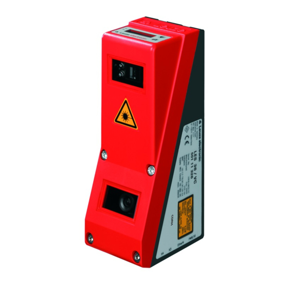
The following shows a light section sensor as an example. An overview of the available types may be found in chapter 15.1 Figure 4.1: Mechanical design of Leuze light section sensors 4.1.2 General performance characteristics • Light section sensor for object detection •... -
Page 21: Line Range Sensor - Lrs
Device description 4.1.3 Line Range Sensor - LRS Line Range Sensors are designed to perform proximity object detection along the laser line. Similar to a light barrier or a laser scanner, the sensor detects the presence of objects through scanning. With individual configuration, one sensor can be used to detect single or multiple objects. -
Page 22: Operating The Sensor
LRSsoft. Detection operation In detection operation, the LRS 36/6 is connected to the process control via its 4 switching outputs; the LRS 36/PB is connected to the process control via PROFIBUS. Alternatively, the LRS can be operated via the Ethernet interface on X2, see chapter 10 "Integrating the LRS in the process control (Ethernet)". -
Page 23: Triggering - Free Running
- The shortest possible time interval between two successive trigger edges is 10ms. Notice! Ex works, the LRS is set to Free Running (shown on display: fRun). In order for it to respond to signals on the trigger input, the operating mode must be set via the LRSsoft con- figuration software to Input Triggered (shown on display: Trig). -
Page 24: Profibus Trigger
So that a measurement can be triggered on each PROFIBUS cycle, the PROFIBUS trigger of the LRS responds to a change of master output byte uTrigger. The control only needs to increment the trigger value in order to initiate a new measurement. -
Page 25: Detection Functions Lrs
4.3.1 Inspection Task The LRS lets you operate with up to 16 individual inspection tasks, each of which may contain up to 16 rectangular analysis windows (AWs) that can be configured independently and that may overlap arbitrarily. 1-16 AWs can be defined for each inspection task. The results of the individual AWs may be combined via logic operations (AND, OR, NOT). -
Page 26: Analysis Results
Detailed evaluation results such as, e.g., the status of all AWs, the number of hit points and the state of the switching outputs are transmitted via Ethernet and can be queried via PROFIBUS. For more information please refer to chapter 10. Technical description LRS Leuze electronic... -
Page 27: Definition Of Aws And Analysis Results
Object points No object detection due (hit points) to shadowing in the detection range Objects Line length 600mm x axis Figure 4.6: Principle of object detection - areas with laser occlusion are shown in orange Leuze electronic Technical description LRS... -
Page 28: Application Examples
AW3 is used to check whether the container is empty. It is not empty if hit points are detected in AW3. Figure 4.7: Zero check of cases Technical description LRS Leuze electronic... -
Page 29: Single Or Multiple Track Presence/Absence Detection On Transport Systems
The settings necessary for the configuration of the AWs, the assignment of the AW states to the switching outputs and the configuration of general parameters such as operating mode, activation, cascading, detection range (FOV) etc. are carried out in LRSsoft, see chapter 9.4 "Parameter settings/Parameters tab" and chapter 9.7. Leuze electronic Technical description LRS... -
Page 30: Installation And Mounting
15.1 Figure 5.1: Device name plate LRS Save the original packaging for later storage or shipping. If you have any questions concerning your shipment, please contact your supplier or your local Leuze electronic sales office. -
Page 31: Mounting The Lrs
Installation and mounting Mounting the LRS The light section sensors can be mounted in different ways: • By means of two M4x6 screws on the back of the device. • Using a BT 56 mounting device on the two fastening grooves. -
Page 32: Bt 56 Mounting Device
5.2.1 BT 56 mounting device The BT 56 mounting device is available for mounting the LRS using the fastening grooves. It is designed for rod installation (Ø 16mm to 20mm). For ordering instructions, please refer to chapter "Type overview" on page 111. -
Page 33: Bt 59 Mounting Device
Installation and mounting 5.2.2 BT 59 mounting device The BT 59 mounting device is available for mounting the LRS on ITEM profiles using the fastening grooves. For ordering instructions, please refer to chapter "Type overview and accessories" on page 111. -
Page 34: Device Arrangement
• The optimal perspective for detecting the relevant contours of objects, see chapter 3.2.1 "Occlusion". Attention, laser radiation! When mounting and aligning the LRS, avoid reflections of the laser beam off reflective sur- faces! Notice! The prevention of ambient light due to shielding of the sensor for example, ensures stable and precise measurement values. -
Page 35: Attach Laser Warning Sign
If the signs would be concealed as a result of the mounting situation of the LRS, attach the signs in the vicinity of the LRS such that reading the signs cannot lead to looking into the laser beam! When installing the LRS in North America, also attach the stick-on label saying "Complies... -
Page 36: Electrical Connection
An overview of the available types may be found in chapter 15.1 Figure 6.2: Connections of the LRS The pin assignment of X1 and X2 is identical for all light section sensors; X3 and X4 differ depending on device type. -
Page 37: Safety Notices
The housing of the LRS contains no parts that need to be adjusted or maintained by the user. Before connecting the device please ensure that the supply voltage matches the value print- ed on the nameplate. -
Page 38: Shielding And Line Lengths
(grounding strip, …). If the LRS does not yet have an FE screw of its own, please use one of the M4 holes on the dovetail. -
Page 39: General Shielding Information
Carefully ground all parts of the machine and of the switch cabinet using copper strips, ground rails or grounding cables with large cross section. Below, the EMC-compliant connection of the light section sensors LRS is described in prac- tical use with images. -
Page 40: Connect The Ground Potential To The Light Section Sensors
• Galvanized mounting sheet steel Comment: Depicted shield components from Wago, series 790 ...: - 790-108 Shield clamping bracket 11 mm - 790-300 Busbar holder for TS35 Figure 6.4: Connecting the cable shield in the switch cabinet Technical description LRS Leuze electronic... -
Page 41: Connecting The Cable Shield To The Plc
• Mounting rails must be well grounded Comment: Depicted shield components from Wago, series 790 ...: - 790-108 Shield clamping bracket 11 mm - 790-112 Carrier with grounding foot for TS35 Figure 6.5: Connecting the cable shield to the PLC Leuze electronic Technical description LRS... -
Page 42: Connecting
The trigger input is used for synchronizing the measurement with the process and for synchronizing cascaded sensors. Detailed information on this topic can be found in chapter 4.2.3 and chapter 4.2.4. The internal equivalent circuit is shown in figure 6.6. Technical description LRS Leuze electronic... -
Page 43: Cascading Output Outcas
LED (see "LED status displays" on page 44). 6.3.2 Connection X2 - Ethernet Attention! All cables must be shielded! The LRS makes either the Ethernet interface available as host interface. X2 (4-pin socket, D-coded) Name Core color Remark... -
Page 44: Connection X3 - Switching Inputs/Outputs (Only Lrs 36/6)
Electrical connection 6.3.3 Connection X3 - switching inputs/outputs (only LRS 36/6) X3 (8-pin socket, A-coded) Name Core color Remark Out4 Output detection result 4 Out4 Out3 Output detection result 3 InSel 2 Ground InSel 1 Out2 Output detection result 2... -
Page 45: Connection X4 - Profibus Dp (Only Lrs 36/Pb)
LRS 36/PB without interrupting the PROFIBUS cable. The external Y plug adapter is also needed if the LRS 36/PB is the last network device. The external bus terminating resistor (termination) is then connected to this. The 5V-supply for the termination is connected to X4. -
Page 46: Display And Control Panel
Indicator and operating elements of the LRS After switching on the supply voltage +U and following error-free initialization of the device, the green LED illuminates continuously: the LRS is in detection mode. The OLED display shows the alignment aid and the status display. 7.1.1... -
Page 47: Displays
Command mode If the LRS is connected to a control, the control can put the LRS into a command mode in which it receives and executes commands (see chapter 10.2.9 "Evaluation telegram"). In command mode, the OLED display has one line. - Page 48 Display and control panel Notice! If errors occur during operation, these are shown on the display. Notices can be found in chapter 12.3. Technical description LRS Leuze electronic...
-
Page 49: Menu Description
Data Output Attention: the value is permanently set to 1 and cannot be changed. Ethernet Ethernet Factory Settings Here you can set the IP address of the IP Address LRS. 192.168.060.003 Table 7.2: Menu structure Leuze electronic Technical description LRS... - Page 50 Activated Password Check Inactive Slave Address Here, you can set the PROFIBUS address Slave Address of the LRS (0 … 126). With address 126 (default), automatic address assignment Slave Address by the commissioning master is sup- ported. Table 7.2: Menu structure...
- Page 51 Table 7.2: Menu structure Notice! If no button is pressed for three minutes, the LRS exits menu mode and switches to detection mode. The OLED display again displays the alignment aid and the sensor status display. Notice! After changing the PROFIBUS slave address, a power-on reset must be performed in order to permanently accept the address.
-
Page 52: Operation/Navigation
IP Address 192.168.001.111 rejects the new value(in this example, the factory setting 192.168.060.003 remains saved). Editing selection parameters displays the next option for Display (Off). Display returns to the next-higher menu level and retains On. Technical description LRS Leuze electronic... -
Page 53: Reset To Factory Settings
Interrupting a reset Pressing causes the adjacent display to appear. If you now press the FactorySettings Execute button, you will exit the menu without resetting the LRS to factory settings. Executing a reset Pressing the button while the checkmark (... -
Page 54: Commissioning And Configuration
In order to be able to establish an UDP communication with the PC, the IP address of your PC and the IP address of the LRS must lie in the same address range. The LRS has no built- in DHCP client, so that you need to set the address manually. This is done the easiest way via the PC. -
Page 55: Setting An Alternative Ip Address On The Pc
Set the subnet mask of the PC to the same value as on the LRS. Close the configuration dialog by confirming all windows using OK. Connect the interface X2 of the LRS directly to the LAN port of your PC. Use a KB ET-…-SA-RJ45 cable for the connection, see table 15.7 The PC first tries to establish a network connection via the automatic configuration. -
Page 56: Commissioning
If you would like to set different values, you must change the values via the display of the LRS in menu item Ethernet (see "Menu description" on page 47). You can test the changed values by entering them in the Configuration area in LRSsoft and then clicking the Check Connectivity button. -
Page 57: Lrssoft Configuration Software
In the next window, you can select which configuration software you would like to install. You will need LPSsoft for configuring light section sensors of the LPS series. You will need LRSsoft for configuring light section sensors of the LRS series. You will need LESsoft for configuring light section sensors of the LES series. - Page 58 LRSsoft configuration software Therefore keep in the Choose Setup Language window the selection English and click on OK. Technical description LRS Leuze electronic...
- Page 59 LRSsoft configuration software Depending on the configuration of your Windows system, the dialog shown below may then appear (missing component VCREDIST_X86). Click on Install. Two additional installation windows will appear, which do not require any further entry. Leuze electronic Technical description LRS...
- Page 60 After some time (up to several minutes depending on the system configuration) the start screen of the MCR installer will appear. Click on Next. The window for entering user data appears. Enter your name and the company name and then click on Next. Technical description LRS Leuze electronic...
- Page 61 Click on Next and in the next window click on Install. The installation will start and a status window will be displayed. This can again take several minutes. Following successful MCR installation, the InstallShield Wizard Completed window appears. Click on Finish to end the MCR-installation. Leuze electronic Technical description LRS...
- Page 62 Keep the default folder in this case as well and click on Next. Upon completion of the installation process, the window shown above appears. The installation routine added a new Leuze electronic program group in your Start menu that contains the installed programs LRSsoft/LPSsoft/LRSsoft.
-
Page 63: Possible Error Message
Path entry. Click on Path and then on Edit The Edit variable window system opens. There in the Variable value field you will find the ;C:\Programs\MATLAB\MATLAB Compiler Runtime\v79\runtime\win32 entry right at the end. Leuze electronic Technical description LRS... -
Page 64: Starting Lrssoft/Communication Tab
Figure 9.1: Initial screen LRSsoft In the IP Configuration area, enter the settings for the LRS and click on Accept. You had already determined this data in chapter 8.2. Click on Check Connectivity to test the connection to the LRS. -
Page 65: Profibus Settings (Only Lrs 36/Pb)
• Analog output status (Analog Output) Notice! Once the LRSsoft has established a connection to the LRS, the laser beam flashes. PROFIBUS settings (only LRS 36/PB) For PROFIBUS devices, you can set the slave address and the baud rate in the PROFIBUS tab. - Page 66 After changing the PROFIBUS slave address via the display or LRSsoft, a power-on reset must be performed in order to permanently accept the address. For the changed settings to take effect, they must be transferred to the sensor! Technical description LRS Leuze electronic...
-
Page 67: Parameter Settings/Parameters Tab
Figure 9.3: Parameter settings in LRSsoft First go to the Task Parameters panel and set the values required for operating the LRS. Then go to the Analysis Functions panel and define analysis windows and their logic combination for your inspection task. Finally, save these settings as an Inspection Task by clicking on Apply Settings or Transmit to Sensor. -
Page 68: Operation Mode
9.7, "Definition of inspection tasks" on page 76 . Operation Mode In Operation Mode you can configure using Free Running that the LRS continuously detects and outputs measurement data (factory setting). With Input Triggered the LRS captures measurement data only if a rising edge is present at the trigger input or if one of the "Ethernet Trigger"... -
Page 69: Field Of View
LRSsoft configuration software Field of View Using Field of View you can restrict the detection range of the LRS. The same happens if you click on the square handles of the detection range framed in blue with the mouse and then pull. -
Page 70: Analysis Functions Area
When clicking on the check box Active in one of the 16 lines AW01 to AW16, a black frame with handles appears in the display of the detection range on the left: Figure 9.5: Definition of analysis windows (AW) Technical description LRS Leuze electronic... - Page 71 By using a logic combination of the analysis results of these 4 AWs, you can configure the switching behavior of outputs Out1 to Out4 and the PROFIBUS process data in the Analysis Window Combination Tables panel. Leuze electronic Technical description LRS...
-
Page 72: Edit Logical Combinations
Parameter settings for control of the switching outputs Notice on analysis depth: By selecting a large value for the analysis depth, the LRS has a reliable switching behavior; the response time of the sensor increases correspondingly (example: analysis depth = 3 ->... -
Page 73: Figure 9.7: Definition Of Logic Combinations Of Several Aws
Because the columns of OUT1 are linked with OR, OUT1 is active and displayed in green. The analysis depth Ana. Depth is set to 10. This means that 10 identical evaluations must occur in sequence in order to cause the switching output to toggle. Leuze electronic Technical description LRS... -
Page 74: Single Shot Mode Area
Inspection tasks 0-15 can be selected via PROFIBUS. Notice! If Enable External Inspection Task Selection is ticked, the inspection task can only be selected via the inputs or PROFIBUS. In this case, the drop-down menu under Inspection Task Selection has no function. Technical description LRS Leuze electronic... -
Page 75: Detection Function/Visualization Tab
Recording -> Archive -> Open Record menu. Notice! After opening a detection data set, the current parameter setting of the LRS should be trans- mitted (see chapter 9.6.2) so that the current sensor configuration is displayed on Hits On and Hits Off. -
Page 76: Menu Commands
• Transmit to Sensor permanently stores all parameter settings of all defined inspection tasks from the configuration software in the LRS. • Reset to factory settings resets the LRS to factory settings. Technical description LRS Leuze electronic... -
Page 77: Managing Detection Data/Measure Records Menu
The enlarged section can then be shifted with the activated hand function to display the area of interest. Notice! The click-and-drag method for zooming known from other programs is not possible here. Before LPSsoft is operated further, the tool buttons (Zoom, Pan, …) must be activated. Leuze electronic Technical description LRS... -
Page 78: Definition Of Inspection Tasks
(Edit Analysis Windows button); confirm each of the set (E)AWs with Apply Settings. - Within an AW, the pixels of the current 2D profile are determined by the LRS (Current Hits). - For each AW, the user then configures an upper and a lower limit for the hits (Hits On/Off) and thus a switching hysteresis. -
Page 79: Integrating The Lrs In The Process Control (Ethernet)
Example: for command 0x434E (Connect to Sensor) a Windows PC must transmit 0x4E and 0x43 in order for it to be understood by the LRS. In the transaction number of the answer from LRS there is then also 0x4E43 (byte sequence 0x43, 0x4E). -
Page 80: Protocol Structure
Length of the header: 30 bytes For sensor models with encoder input, these 4 bytes contain the encoder value. With the LRS, this value is always 0x0000 0000. 10.2.1 Command number The command number specifies both the command from the control to the sensor as well as the command from the sensor to the control (see chapter 10.3). -
Page 81: 10.2.4 Status
Integrating the LRS in the control (Ethernet) 10.2.4 Status Indicates the state of the sensor. The state is coded as follows: High-Byte LSB MSB Low-Byte LSB Meaning of the bits - 0 Sensor not connected via Ethernet - 1 Sensor connected via Ethernet... -
Page 82: 10.2.6 Scan Number
Indicates the number of user data transferred. The fixed default value in detection mode is 0x0059. 10.2.9 Evaluation telegram In detection mode for the LRS, the evaluation telegram is transmitted with command number 0x5354. After the header are 53 user data words with the following structure: Byte... -
Page 83: Ethernet Commands
The sequence in which the individual bytes of the commands and of the protocol must be transmitted in order to be processed by the LRS corresponds to the "little-endian" byte sequence. The response of the LRS also corresponds to the "little-endian" standard. For further information, see the notice in chapter 10.2. -
Page 84: 10.3.1 Elementary Commands
10.3.1 Elementary commands Using the Connect to sensor and Disconnect from sensor commands, a connection between control and sensor is established or terminated. The communication with the LRS is carried out via the ports previously configured in LRSsoft. Command from control to LRS Answer from LRS to control Command no. -
Page 85: 10.3.2 Commands In Command Mode
Integrating the LRS in the control (Ethernet) To switch between detection mode and command mode the Enter Command Mode and Exit Command Mode commands are available. Command from control to LRS Answer from LRS to control Command no. Meaning Command no. Meaning... -
Page 86: User Data In Command Mode (Command Parameters)
SF = SaveFlag If SF=0 then the inspection task is changed only temporarily. If SF=1 then the newly set inspection task is retained even after a restart of the LRS. Get Actual Inspection Task The LRS responds to sensor control command 0x0049 with 0x004A and one word of user... -
Page 87: Set Scan Number
Integrating the LRS in the control (Ethernet) Set Scan Number For sensor control command 0x0053, one word of user data is transmitted to the sensor: Byte High-Byte Low-Byte LSB Meaning of the bits 31…32 S16 S15 S14 S13 S12 S11 S10 S9 S8 S7 S6 S5 S4 S3 S2 S1 New scan number that is to be set With the sensor control command Set Scan Number, it is possible to set a uniform scan number for the transmission protocol for multiple sensors operated in cascaded operation. - Page 88 Integrating the LRS in the control (Ethernet) Parameters and settings: If SF=0, then the parameter is changed only temporarily. If SF=1, the parameter is retained even following a restart of the LRS. Parameter ID Parameter meaning Valid parameter values Parameter...
-
Page 89: Get Single Inspection Task Parameter (Beginning With Firmware V01.40!)
• Setting of cascading output (Cascading Output: Enable or Disable), • Exposure duration of the laser (Light Exposure), • Detection range of the LRS (Field of View). Command syntax from control to sensor: 0xFFFF 0xFFFF 0x0000 0x006F 0x0000 0x0000 0x0000 0x0000 0x0000 0x0000 0x0000 0x0000 0x0000 0x0010 0x0001... - Page 90 Integrating the LRS in the control (Ethernet) Answer from sensor to control: 0x0009- 0xFFFF 0xFFFF 0x0000 0x0070 0x0000 0x0000 0x0000 0x006F 0x0000 0x0000 0x0000 0x0000 0x0000 0x0010 0x0014 Byte High-Byte LSB MSB Low-Byte LSB Meaning of the bits 31…32 Parameter ID for parameter selection 33…34...
-
Page 91: 10.3.4 Commands In Detection Mode
Integrating the LRS in the control (Ethernet) 10.3.4 Commands in detection mode The following commands are available in detection mode: Command from control to LRS Answer from LRS to control User User Command no. Meaning data Command no. Meaning data... -
Page 92: Command With User Data
Integrating the LRS in the control (Ethernet) Command with user data Set Actual Inspection Task (LRS in command mode, activate Task 15 and do not store in volatile memory) PC to LRS: 0xFFFF 0xFFFF 0x0000 0x004B 0x0000 0x0000 0x0000 0x0000 0x0000 0x0000 0x0000 0x0000 0x0000 0x0000... -
Page 93: Operation With Lxs_Lib.dll
The LxS_Lib.dll is a .NET 2.0-compatible collection of functions which considerably facili- tates the integration of all Leuze light section sensors (LPS, LRS and LES) into PC environ- ments. The LxS_Lib.dll can be used in a variety of programming languages, such as C#, Visual Basic, etc. -
Page 94: Integration Of The Lrs 36/Pb In The Profibus
• Activation and trigger via PROFIBUS The restriction on the selection of maximum 8 inspection tasks via the switching inputs for the LRS 36/6 does not exist for the LRS 36/PB. Up to 16 different inspection tasks can be activated by the control... -
Page 95: Profibus Address Assignment
Automatic address assignment via the PROFIBUS (slave address 126) is preset. Automatic address assignment The LRS 36/PB supports automatic detection of the baud rate and automatic address assignment via the PROFIBUS. The address of the PROFIBUS participant can be set automatically by the commissioning tool of the PROFIBUS system (a class 2 PROFIBUS master). -
Page 96: General Information About The Gsd File
Described parameters (P) are parameters of the GSD file in the control. Notice! The current version of the GSD file LEUZE401.GSD for the LRS 36/PB can be found on the Leuze website at Download -> detect -> Measuring sensors. Technical description LRS... -
Page 97: Overview Of The Gsd Files
The LRS 36/PB has one module slot. Select the corresponding module from the GSD to set the process data of the LRS 36/PB that are to be transmitted . Several modules are available for selection. Beginning with the simplest input module M1, additional inputs are included with the subsequent modules. -
Page 98: Input Data (From Viewing Position Of Control)
Integration of the LRS 36/PB in the PROFIBUS Input data (from viewing position of control) Position Name Bits in byte Value Meaning Module (bytes) range Bit7 Bit6 Bit5 Bit4 Bit3 Bit2 Bit1 Bit0 wScanNum (HighByte) SN_b15 SN_b14 SN_b13 SN_b12 SN_b11 SN_b10 SN_b9 SN_b8 0 … 255 Scan number (Highbyte) -
Page 99: Output Data Description
So that a measurement can be triggered on each PROFIBUS cycle, the PROFIBUS trigger of the LRS responds to a change of master output byte uTrigger. The control only needs to increment the trigger value in order to initiate a new measurement. -
Page 100: Input Data Description
Integration of the LRS 36/PB in the PROFIBUS 11.6 Input data description Several modules are available for selection. Beginning with the simplest input module M1, additional inputs are included with the subsequent modules. All available output data are already contained in module M1. The modules with higher numbers the modules with the lower numbers (example: M2 contains M1 and the extensions of M2). -
Page 101: Sensor State
Integration of the LRS 36/PB in the PROFIBUS Sensor state Sensor status byte uSensorState contains the following information: Designation Meaning ErrM Error mode, permanent sensor malfunction. Command mode: the sensor is in command mode. The queries from the control are not processed and the measurement data are frozen (indicated by the constant scan number). -
Page 102: 11.6.3 Module M3
Notice! The restriction for the logic combinations in the LRS 36/6 to 4 switching outputs can thereby be circumvented and the control can define further switching outputs itself via logic com- binations of its own. -
Page 103: Number Of Hit Points (Current Hits) In Analysis Window 6
Integration of the LRS 36/PB in the PROFIBUS Number of hit points (Current Hits) in analysis window 6 Number of hit points (Current Hits) in analysis window 9 See description under Number of hit points (Current Hits) in analysis window 1 in chapter 11.6.3... -
Page 104: Diagnostics And Troubleshooting
See "Set Laser Gate" on page 84. "Set Laser Gate" com- mand Sensor in trigger mode Activate single measurement by means of Ethernet trigger or via PIN 5 on X1 or via PROFIBUS. Table 12.1: General causes of errors Technical description LRS Leuze electronic... -
Page 105: Interface Error
Ethernet" on page 52. Incorrect port assigned to Using ping command check whether the sensor LRS / control responds. If so, check port assignment to LRS and control. The set ports must match. Firewall blocks ports Switch off firewall temporarily and repeat connection test. -
Page 106: Error Messages In Display (Starting From Firmware V01.40)
Error messages in display Notice! If deviating error messages occur, contact your Leuze distributor or service organization. Please disconnect the sensor from the supply voltage and eliminate the cause of the error. If a short-circuit occurs on the output, the following is displayed: Output Overload Reset ->... - Page 107 Country: Have the following information ready for the service department: - File: LRSsoft.log (located in the installation directory of LRSsoft) - Configuration file *.lrs, if necessary screenshots, figures, etc. Leuze Service fax number: +49 7021 573 - 199 Leuze Service e-mail for the LOS product unit: service.detect@leuze.de...
-
Page 108: Maintenance
General maintenance information Usually, the light section sensor does not require any maintenance by the operator. Cleaning In the event of dust buildup, clean the LRS with a soft cloth; use a cleaning agent (commercially available glass cleaner) if necessary. Notice! Do not use aggressive cleaning agents such as thinner or acetone for cleaning the light sec- tion sensors. -
Page 109: Specifications
3 (inspection task selection) on X3 (only LRS 36/6 and LRS 36/6.10) Signal voltage high/low -2V)/ 2V PROFIBUS (only LRS 36/PB) Interface type 1x RS 485 on X4 (only LRS 36/PB) Protocols PROFIBUS DP/DPV1 slave Baud rate 9.6kBaud … 6stMBaud Indicators... - Page 110 Number of detection fields: up to 16 with logic operation option Number of inspection tasks: up to 16 (8 of these can be activated via inputs) 1=transient protection, 2=polarity reversal protection, 3=short circuit protection for all outputs, requires external protective circuit for inductive loads Technical description LRS Leuze electronic...
-
Page 111: Typical Detection Range
Specifications 14.2 Typical detection range -300 x = Line length -225 -150 Detection range +150 +225 +300 Figure 14.1: Typical detection range LRS Leuze electronic Technical description LRS... -
Page 112: Dimensioned Drawing
M4 thread, 4.5 deep Holder for mounting system BT 56 / BT 59 Zero point and orientation of the coordinate system for detection data 4mm bore hole in transmitter axis Figure 14.2: Dimensioned drawing LRS Technical description LRS Leuze electronic... -
Page 113: Type Overview And Accessories
LRS 36/PB Line profile sensor for product detection (also multi-track), 50111332 detection range 200 … 800mm, line length 600mm, Ethernet interface, PROFIBUS DP Table 15.2: Type overview LRS 15.1.3 LES Type designation Description Part no. LES 36/VC Line profile sensor for edge detection and object measurement (also multi-track), 50111326 detection range 200 …... -
Page 114: Accessories
500 27375 BT 59 Mounting device featuring dovetail for ITEM profile 50111224 Table 15.4: Mounting devices for the LRS 15.2.2 Accessory ready-made cables for voltage supply X1 Contact assignment for connection cable X1 Connection cable X1 (8-pin socket, A-coded) Name... -
Page 115: Order Codes Of The Cables For Voltage Supply
Cable length 25m 678063 CB-M12-50000E-8G Cable length 50m 678064 Table 15.6: X1 cables for the LRS 15.2.3 Accessories for Ethernet interface X2 Ready-made cables with M12 plug/open cable end M12 Ethernet connection cables (4-pin plug, D-coded, open cable end) Name Pin (M12) -
Page 116: Ready-Made Cables With M12 Plug/Rj-45 Plug
KB ET - 10000 - SSA Cable length 10m 50106901 KB ET - 15000 - SSA Cable length 15m 50106902 KB ET - 30000 - SSA Cable length 30m 50106905 Table 15.12: Ethernet connection cables featuring M12 plug/M12 plug Technical description LRS Leuze electronic... -
Page 117: Connectors
KDS ET M12 / RJ 45 W - 4P Converter from M12 D-coded to RJ 45 socket 50109832 Table 15.13: Connectors for the LRS 15.2.4 Accessories ready-made cables for X3 (only LRS 36/6) Contact assignment for X3 connection cables X3 (8-pin plug, A-coded) Name Core color... -
Page 118: Connection Accessories / Ready-Made Cables For X4 (Only Lrs 36/Pb)
Type overview and accessories 15.2.5 Connection accessories / ready-made cables for X4 (only LRS 36/PB) Contact assignment for X4 connection cables X4 (5-pin connector, B-coded) Name Remark N.C. – Receive/transmit data RxD/TxD-N, green N.C. – N.C. 3 N.C. Receive/transmit data RxD/TxD-P, red N.C. -
Page 119: Order Code Of Profibus Connection Cables For X4
CD TD LRS 36 CD with configuration software for light section sensors 50111933 Table 15.19: Configuration software for the LRS Notice! The current version of the configuration software can be found on the Leuze website. Leuze electronic Technical description LRS... -
Page 120: Appendix
The analysis depth can be set for each output individually (differently). Analysis Window (AW) Rectangular area of the LRS in which objects are detected. An object is only detected if the number of object measurement points (current hits) is greater than or equal to the defined minimum number of measurement points (Hits On). - Page 121 Inspection Task Summary of all settings, which are required to solve an application. The LRS per- mits working with up to 16 individual inspection tasks. Each task can contain up to 16 AWs that are independently configurable and may overlap arbitrarily. Each...
-
Page 122: Revision History / Feature List
(useful for PLC evaluation) Ethernet trigger Reduction of data quantity (useful for PLC evaluation), reduction in cabling Beginning PROFIBUS other LRS 36/PB device types LxSsoft V1.30 (LPSsoft V1.30, with V01.25 support with PROFIBUS LRSsoft V1.20) Ethernet sensor activation Activation now possible via... -
Page 123: 16.2.2 Configuration Software
Trigger operation is also LRS 36, LPS 36: supported while configuration optimized diagnosis in trigger operation software is running Display of encoder counter value LRS 36/EN: visualization encoder New: Encoder parameters LRS 36/EN: encoder interface configuration: single-/multi-channel encoder, overflow values, reversal of direction of rotation LxSsoft V1.30 (LPSsoft V1.30,... -
Page 124: Index
Mutual interference Electrical data Encoder count Environment variable Name plate Environmental data Error limits Error message Ethernet cable assignment Occlusion Ethernet connection OLED display Ethernet interface Optical data Evaluating measurement data Exposure duration Exposure setting Technical description LRS Leuze electronic... - Page 125 Measurement frequency Measurement rate Module Output data Outputs Parameter Slave Receiver occlusion Receiving optics Repair Rod installation Safety standard Servicing Shielding System requirements System variable Termination Timing Triangulation principle Trigger input Trigger time Troubleshooting Type overview Leuze electronic Technical description LRS...
Need help?
Do you have a question about the LRS and is the answer not in the manual?
Questions and answers