Sign In
Upload
Manuals
Brands
Leuze Manuals
Accessories
LBK S-01
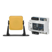
User Manuals: Leuze LBK S-01 Safety radar sensor
Manuals and User Guides for Leuze LBK S-01 Safety radar sensor. We have
2
Leuze LBK S-01 Safety radar sensor manuals available for free PDF download: Original Operating Instructions, Installation Instructions Manual
Leuze LBK S-01 Original Operating Instructions (127 pages)
Safe Radar System
Brand:
Leuze
| Category:
Radar
| Size: 3 MB
Table of Contents
Configuration
2
Table of Contents
3
Glossary of Terms
11
This Manual
12
Information on this Manual
12
Objectives of this Instruction Manual
12
Obligations with Regard to this Manual
12
Provided Documentation
12
Intended Users of this Instruction Manual
12
Safety
13
Safety Information
13
Safety Messages
13
Safety Symbols on the Product
13
Personnel Skills
13
Safety Assessment
14
Intended Use
14
EMC-Compliant Electrical Installation
14
General Warnings
14
Warnings for the Restart Prevention Function
15
Responsibility
15
Limits
15
Disposal
15
Conformity
16
Standards and Directives
16
Fcc
16
Srrc
17
Imda
17
Certificações ANATEL
17
Ncc
17
Icasa
18
Rohs2 China
18
National Restrictions
20
France and the United Kingdom
20
Japan
20
South Korea
20
Argentina
21
Mexico
21
Russian Federation
21
China
22
Get to Know LBK S-01 System
23
LBK S-01 System
23
Definition
23
Special Features
23
Main Components
23
Controller - Sensor Communication
24
Controller - Machinery Communication
24
Applications
24
LBK S-01 System Controllers
25
Controller Supported
25
Functions
25
Structures
26
System Status Leds
27
Fieldbus Status Leds
27
Inputs
28
Input Variable Behavior
28
SNS Input
29
Outputs
29
OSSD Diagnostic Checks
31
External Resistor for OSSD Outputs
31
LBK S-01 Sensors
31
Functions
31
Structure
32
Status LED
32
LBK Designer Application
32
Functions
32
LBK Designer Application Usage
32
Authentication
33
Main Menu
33
Fieldbus Communication
34
Fieldbus Support
34
Communication with the Machinery
34
Data Exchanged through Fieldbus
35
MODBUS Communication
36
MODBUS Support
36
MODBUS Communication Enabling
36
Data Exchanged through MODBUS
36
System Configuration
37
Dynamic System Configuration
37
Dynamic System Configuration Activation
37
Dynamic Configuration through the Digital Inputs
37
Dynamic Configuration through the Safety Fieldbus
38
Safe Configuration Switch
39
Functioning Principles
40
Sensor Functioning Principles
40
Introduction
40
Factors that Influence the Sensor Field of View and Object Detection
40
Factors that Influence the Reflected Signal
40
Detected and Missed Objects
40
Detection Fields
40
Detection Field Parameters
41
Detection Fields Dependency and Detection Signal Generation
42
System Category (According to en ISO 13849)
43
System Safety Degree
43
PL D, Category 2 Configuration
43
PL D, Category 3 Configuration
43
Safety Working Modes and Safety Functions
45
Introduction
45
Safety Working Modes
45
Safety Working Modes Examples
45
Safety Working Mode: both (Default)
49
Introduction
49
Safety Function: Access Detection
49
Safety Function: Restart Prevention
50
Safety Working Mode: Always-On Access Detection
50
Safety Function: Access Detection
50
TOFF Parameter
50
Safety Working Mode: Always-On Restart Prevention
50
Features of the Restart Prevention Function
51
Cases of Non-Guaranteed Function
51
Types of Managed Restart
52
Precautions for Preventing Unexpected Restarting
53
Configure the Restart Prevention Function
53
Muting
53
Description
53
Muting Enabling
54
Muting Activation Conditions
54
Enable Muting Signal Characteristics
55
Muting Status
55
Anti-Tampering Functions: Anti-Rotation Around Axes
55
Anti-Rotation Around Axes
55
Enable the Anti-Rotation Around Axes Function
56
When to Enable
56
Checks When the Anti-Rotation Around Axes Function Is Disabled
56
Anti-Tampering Functions: Anti-Masking
57
Masking Signal
57
Environment Memorization Process
57
Causes of Masking
57
Masking Signal When the System Is Turned on
57
Sensitivity Level
57
Checks When the Anti-Masking Function Is Disabled
58
When to Disable
58
Multi-Controller Synchronization
58
Introduction
58
Network Topology
59
Trigger Source
59
Required Signal
59
Enable the Multi-Controller Synchronization Function
60
Electrical Connections
61
Sensor Position
63
Basic Concepts
63
Determining Factors
63
Sensor Installation Height
63
Sensor Inclination
63
Sensor Field of View
63
Types of Field of View
63
Features of the 50° Field of View
64
Areas and Dimensions of the Field of View
64
Dimensions of the 110° Field of View
64
Dimensions of the 50° Field of View
65
Sensitivity
65
Dangerous Area Calculation
65
Introduction
65
Sensor Height ≤ 1 M
65
Sensor Height > 1 M
66
Calculation of Position for Sensor Height ≤ 1 M
67
Introduction
67
Overview of Possible Installation Configurations
67
Legend
68
Configuration 1
69
Configuration 3
71
Calculate the Real Detection Distance
71
Calculation of Position for Sensor Height > 1 M
72
Introduction
72
110° Field of View
72
50° Field of View
73
Calculate the Real Detection Distance
73
Outdoor Installations
73
Position Exposed to Precipitation
73
Recommendations for Covering the Sensor
74
Recommendations for Positioning the Sensor
74
Position Not Exposed to Precipitation
74
Installation and Use Procedures
75
Before Installation
75
Materials Required
75
Operating System Required
75
Install the LBK Designer Application
75
Initiate LBK S-01 System
75
Install and Configure LBK S-01 System
76
Install the Controller
76
Synchronize the Controllers
76
Define the Area to be Monitored
76
Configure the Inputs and Outputs
77
Install Sensors on the Floor
77
Install the Sensors on the Machinery
79
Connect the Controller to the Sensors
80
Assign the Node Ids
80
Chain Examples
81
Save and Print the Configuration
81
Set the Controller Ethernet Parameters
81
Validate the Safety Functions
82
Validation
82
Validate the Access Detection Function
82
Example of Access Points
83
Validate the Restart Prevention Function
83
Example of Stopping Points
84
Validate the System with LBK Designer
84
Troubleshooting Validation
84
Manage the Configuration
84
Configuration Checksums
84
Configuration Reports
85
Change the Configuration
85
Back up the Configuration
86
Load a Configuration
86
Display Previous Configurations
86
Other Functions
86
Change Language
86
Locate the Area with Detected Motion
86
Change the Admin Password
86
Restore Factory Default Settings
86
Identify a Sensor
86
Change Network Parameters
87
Change Modbus Parameters
87
Change Fieldbus Parameters
87
Set Labels
87
Maintenance and Troubleshooting
88
Troubleshooting
88
Controller LED
88
Sensor LED
90
Other Problems
91
Event Log Management
91
Introduction
91
Download the System Log
91
Log File Sections
92
Log Line Structure
92
Timestamp (Seconds Counter from the Latest Boot)
92
Timestamp (Absolute/Relative Value)
92
Event Description
93
Log File Example
93
Event List
94
Verbosity Level
94
Verbosity Level for Detection Access and Exit Events
95
INFO Events
95
System Boot
95
System Configuration
95
Factory Reset
96
Stop Signal
96
Restart Signal
96
Detection Access
96
Detection Exit
96
Dynamic Configuration in Use
97
Muting Status
97
Fieldbus Connection
97
MODBUS Connection
97
Session Authentication
97
Validation
97
Log Download
98
ERROR Events (Controller)
98
Introduction
98
Temperature Errors (TEMPERATURE ERROR)
98
Controller Voltage Errors (POWER ERROR)
98
Peripheral Error (PERIPHERAL ERROR)
98
Configuration Errors (FEE ERROR)
99
Output Errors (OSSD ERROR)
99
Flash Errors (FLASH ERROR)
99
Dynamic Configuration Error (DYNAMIC CONFIGURATION ERROR)
99
Internal Communication Error (INTERNAL COMMUNICATION ERROR)
99
Input Redundancy Error (INPUT REDUNDANCY ERROR)
99
Fieldbus Error (FIELDBUS ERROR)
99
RAM Error (RAM ERROR)
99
Sensor Configuration Errors (SENSOR CONFIGURATION ERROR)
99
ERROR Events (Sensor)
100
Introduction
100
Radar Signal Errors (Signal Error)
100
Temperature Errors (TEMPERATURE ERROR)
100
Sensor Voltage Errors (POWER ERROR)
100
Anti-Tampering Sensor (ACCELEROMETER ERROR)
101
Peripheral Error (PERIPHERAL ERROR)
101
ERROR Events (CAN Bus)
101
Introduction
101
CAN Errors (CAN ERROR)
101
Cleaning and Spare Parts
101
Cleaning
101
Spare Parts
101
Technical References
102
Technical Data
102
General Specifications
102
Safety Parameters
102
Ethernet Connection (if Available)
103
Controller Features
103
Sensor Features
104
CAN Bus Cables Recommended Specifications
105
Side Screw Specifications
105
Bottom Screws Specifications
106
Terminal Blocks and Connector Pin-Outs
106
Digital Inputs and Outputs Terminal Block
106
Voltage and Current Limits for Digital Inputs
107
Power Supply Terminal Block
107
CAN Bus Terminal Block
107
Connectors M12 CAN Bus
108
Electrical Connections
109
Connection of Safety Outputs to the Machinery Control System
109
Connection of Safety Outputs to an External Safety Relay
110
Connection of Stop Signal (Emergency Button)
111
Connection of Restart Signal
112
Connection of the Muting Input and Output (One Group of Sensors)
113
Connection of the Muting Input and Output (Two Groups of Sensors)
114
Detection Signal 2 Connection
115
Diagnostic Output Connection
116
Multi-Controller Synchronization
117
Configuration Application Parameters
117
Parameter List
117
Digital Input Signals
120
Stop Signal
120
Muting (With/Without Pulse)
120
Restart Signal
122
Active Dynamic Configuration
123
10 Appendix
124
System Software
124
Introduction
124
Configuration
124
Competence
125
Installation Instructions
125
Outstanding Anomalies
125
Backward Compatibility
125
Change Control
125
Implemented Security Measures
125
Disposal
125
Service and Support
125
Service Hotline
125
Order Guide
126
Sensors
126
Controllers
126
Accessories
126
Connection Technology - Connection Cables
126
Connection Technology - Interconnection Cables
127
Connection Technology - USB Interconnection Cables
127
Connection Technology - Terminating Resistors
127
Mounting Technology - Protectors
127
Advertisement
Leuze LBK S-01 Installation Instructions Manual (19 pages)
Brand:
Leuze
| Category:
Accessories
| Size: 0 MB
Advertisement
Related Products
Leuze LBK SBV
Leuze LES 36 Series
Leuze LES 36HI Series
Leuze LRS
Leuze LBK ISC
Leuze LBK SBV205
Leuze LBK ISC BUS PS
Leuze LBK ISC-02
Leuze LBK ISC-03
Leuze LBK ISC110
Leuze Categories
Barcode Reader
Accessories
Measuring Instruments
Security Sensors
Safety Equipment
More Leuze Manuals
Login
Sign In
OR
Sign in with Facebook
Sign in with Google
Upload manual
Upload from disk
Upload from URL