
Related Manuals for Quectel SA800U-WF EVB


Summary of Contents for Quectel SA800U-WF EVB
- Page 1 SA800U-WF EVB User Guide Smart Module Series Version: 1.0 Date: 2022-06-23 Status: Released...
- Page 2 Smart Module Series At Quectel, our aim is to provide timely and comprehensive services to our customers. If you require any assistance, please contact our headquarters: Quectel Wireless Solutions Co., Ltd. Building 5, Shanghai Business Park Phase III (Area B), No.1016 Tianlin Road, Minhang District, Shanghai...
- Page 3 Except as otherwise set forth herein, nothing in this document shall be construed as conferring any rights to use any trademark, trade name or name, abbreviation, or counterfeit product thereof owned by Quectel or any third party in advertising, publicity, or other aspects.
-
Page 4: Safety Information
Manufacturers of the cellular terminal shall notify users and operating personnel of the following safety information by incorporating these guidelines into all manuals of the product. Otherwise, Quectel assumes no liability for customers’ failure to comply with these precautions. -
Page 5: About The Document
Smart Module Series About the Document Revision History Version Date Author Description 2022-05-16 Mary SHEN Creation of the document 2022-06-23 Mary SHEN First official release SA800U-WF_EVB_User_Guide 4 / 63... -
Page 6: Table Of Contents
Smart Module Series Contents Safety Information ............................3 About the Document ........................... 4 Contents ............................... 5 Table Index ..............................7 Figure Index ..............................8 Introduction ............................10 1.1. Special Mark ..........................10 Product Overview ..........................11 2.1. Top and Bottom Views ......................11 2.2. - Page 7 Smart Module Series 4.18. Vibrator ............................51 4.19. Buttons and Switches ....................... 52 4.20. Status Indicators ........................53 4.21. Test Points ..........................54 Operation Procedures ........................56 5.1. Turn On the Module ........................56 5.2. Turn Off the Module ........................57 5.3.
- Page 8 Smart Module Series Table Index Table 1: Special Mark ..........................10 Table 2: Components & Functions ......................14 Table 3: Accessories List ..........................19 Table 4: Description of Power Supply ......................22 Table 5: B2B and FPC Connectors ......................25 Table 6: LCM Interface ..........................
- Page 9 Figure 5: SA800U-WF EVB and Accessories Equipment ................18 Figure 6: SA800U-WF EVB Kit Accessories ....................19 Figure 7: Simplified Power Supply Block Diagram of SA800U-WF EVB ..........22 Figure 8: DC Power Supply Interface ......................23 Figure 9: Power Plug Design ........................23 Figure 10: Reference Design for Battery Interface ..................
- Page 10 Smart Module Series Figure 42: Simplified Interface Schematic for SPI to CAN Interface ............45 Figure 43: CAN Connector ......................... 45 Figure 44: Simplified Interface Schematic for Ethernet Interface .............. 46 Figure 45: RJ45 Connector ........................46 Figure 46: Simplified Interface Schematic for M.2 Interface ..............47 Figure 47: M.2 interface ..........................
-
Page 11: Introduction
Smart Module Series Introduction This user guide describes the application details of the SA800U-WF EVB (evaluation board), which is an assistant tool for developers to develop applications and test basic functionalities of applicable modules as follows: ⚫ SA800U-WF ⚫ SG865W-WF 1.1. -
Page 12: Product Overview
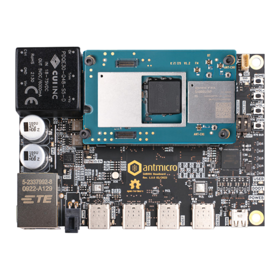
Smart Module Series Product Overview Quectel provides designers with SA800U-WF EVB with a size of 288 mm × 170 mm for developing applications based on applicable modules and basic functions of test modules. 2.1. Top and Bottom Views Figure 1: Top View... - Page 13 Smart Module Series Figure 2: Bottom View Figure 2: Bottom View SA800U-WF_EVB_User_Guide 12 / 63...
-
Page 14: Component Placement
Smart Module Series 2.2. Component Placement J1201 J0503 J0501 J0502 J0433 J0605 J0301 U0436 U0435 U0424 U0428 D0301 J1203 U1301 J0201 S0302 U1304 S0301 U0101 U1302 J0302 J1601 RGB LED U0102 S0601 J1101 J0603 J0601 J0202 S1701 J1301 J0701 S0701 J1401 J1302 U1303... - Page 15 Smart Module Series U0403(EAR) U0445(SPK) Figure 4: Bottom View for Component Placement Table 2: Components & Functions Components RefDes. Description Implementation ⚫ DC power supply: 4.5–18 V J0301 Power jack on the EVB ⚫ Typical supply voltage: 12 V/5 A Power Supply J0302 Li-polymer battery connector...
- Page 16 Smart Module Series ⚫ Support type-C mode, DisplayPort mode and USB OTG ⚫ Used command J0701 USB Type-C connector transmission, data transmission, software debugging and firmware USB Interface upgrade J0901 3 type-A interfaces, only support host J0902 USB Type-A connectors mode J0903 USB_BOOT...
- Page 17 Smart Module Series RM500Q-AE operation status D0801 indicator Power supply of RM500Q-AE D0802 ON/OFF indicator D1201 Red LED D1202 Green LED D1203 Blue LED D1301 D1302 Flashlights D1303 U0101, U0102 Module TE-A Connect to modules TE-A J0201, J0202 J0601 HDMI OUT connector HDMI J1601 HDMI IN connector...
- Page 18 Smart Module Series J1301 MIC Board connector J1302 PWM/ADC/SPI interfaces Reserved pin Reserve for testing control J1203 interfaces TP0103、TP0104、TP0105、TP0201、 TP0402、TP0404、TP0405、TP0412、 TP0413、TP0415、TP0422、TP0423、 TP0425、TP0426、TP0601、TP0602、 Test Points 29 test points TP0603、TP0604、TP0701、TP0702、 TP0803、TP0805、TP0806、TP1101、 TP1402、TP1403、TP1606、TP1607、 TP1608 SA800U-WF_EVB_User_Guide 17 / 63...
-
Page 19: Kit Accessories
Smart Module Series Kit Accessories 3.1. Accessories Assembly USB-to-UART cable Headset Power adapter SA800U-WF Module HDMI cable ethernet cable USB Type-C cable Type-C-to-DP cable Figure 5: SA800U-WF EVB and Accessories Equipment SA800U-WF_EVB_User_Guide 18 / 63... -
Page 20: Accessories List
Smart Module Series 3.2. Accessories List All accessories of the SA800U-WF EVB kit are listed as below. Please contact the supplier if there is something missing. Type-C-to-DP cable Power adapter USB-to-UART cable Driver Disc USB Type-C cable 1 Gb Ethernet cable... - Page 21 Smart Module Series USB-to-UART cable USB Type-C cable HDMI cable Type-C-to-DP cable RF cables Antennas Wi-Fi/Bluetooth antennas Audio Headset ⚫ USB-to-RS232 driver ⚫ Driver Disc USB driver ⚫ Related tools for modules Used for FPC connector Bolts and Nuts Bolts and nuts for assembling the EVB SA800U-WF_EVB_User_Guide 20 / 63...
-
Page 22: Application Interfaces
Smart Module Series Application Interfaces This chapter describes the hardware interfaces of SA800U-WF EVB, shown as follows: ⚫ Power supply interfaces ⚫ B2B and FPC connectors ⚫ LCM interface ⚫ Touch panel interface ⚫ Camera interfaces ⚫ HDMI interfaces ⚫... -
Page 23: Power Supply
(DC-DC converter), which is used to regulate the 12 V DC power supply voltage to 4.2 V for powering up the module. SA800U-WF EVB can also be powered by a Li-polymer battery through the battery connector (J0302) on the board. -
Page 24: Adapter Interface
Figure 8: DC Power Supply Interface Before connecting the power supply, developers have to select a proper 12 V DC power adapter to supply power for the SA800U-WF EVB, and the power plug design of the adapter is shown as below. Inner contact... -
Page 25: Battery Interface
Smart Module Series 4.1.2. Battery Interface The following figure shows a reference circuit design for battery interface. J0302 100nF VBAT_BATT VBAT_BATT BATT_THERM BATT_THERM NM-0R Notices: SA800U-WF: R1=47 K SG865W-WF: R1=100 K Figure 10: Reference Design for Battery Interface The following figure shows the pin assignment of battery interface. J0302 Figure 11: Pin Assignment of Battery Interface SA800U-WF_EVB_User_Guide... -
Page 26: B2B And Fpc Connectors
Smart Module Series 4.2. B2B and FPC Connectors SA800U-WF EVB is connected to the module with two B2B connectors and two FPC connectors: Table 5: B2B and FPC Connectors RefDes. Description U0101 B2B connectors U0102 J0201 FPC connectors J0202 The following two figures show the B2B and FPC connectors and the diagram after assembly of the... -
Page 27: Lcm Interface
See document [1] for detailed information about pin definition corresponding to B2B and FPC connectors on SA800U-WF EVB. 4.3. LCM Interface SA800U-WF EVB video output interface (LCM interface) is based on MIPI_DSI standard and supports 4 groups of high-speed differential data transmission. Table 6: LCM Interface RefDes. - Page 28 Smart Module Series The following figure shows a reference circuit design for LCM interface of the SA800U-WF EVB. LDO14_1V88 LCM_VDD _2V 8 U0602 J0603 VREG_WLED LEDA WLED _SINK1 LEDK WLED _SINK2 LCD0_TE0 LPTE RESET LCD0_RST LCD_ID NC (SDA-TP) NC (SCL-TP) NC (RST-TP) 4.7uF...
-
Page 29: Touch Panel Interface
Smart Module Series 4.4. Touch Panel Interface The SA800U-WF EVB provides a touch panel interface J0605. J0605 is used to realize LCD touch function. The following figure shows a reference design for touch panel interface. Table 7: Touch Panel Interface RefDes. -
Page 30: Camera Interfaces
Smart Module Series 4.5. Camera Interfaces Based on standard MIPI_CSI input interface, SA800U-WF EVB supports two cameras and one TOF camera (4-lane + 4-lane + 2-lane). J0501 supports 1-channel 4-lane MIPI_CSI1, J0502 supports 1-channel 4-lane MIPI_CSI0, the pixels of both cameras are 16 MP. TOF camera interface J0503 supports 1-channel 2-lane MIPI_CSI3, which only supports raw format and does not support Preview. - Page 31 Smart Module Series U0101 J0501 CSI1_CLK_P CSI1_CLK_N MDP2 CSI1_LN2_P MDN2 CSI1_LN2_N MDP0 CSI1_LN0_P MDN0 CSI1_LN0_N MDP3 CSI1_LN3_P MDN3 CSI1_LN3_N MDP1 CSI1_LN1_P MDN1 CSI1_LN1_N 10 K ID(DOVDD) LVS1A_1V8 PWDN CAM1_PWDN RESET CAM1_PWDN CCI_I2C_SDA1 CCI_I2C_SCL1 DVDD_1V2 CAM1_DVDD_1V1 MCLK CAM1_MCLK1 2.2 K 2.2 K DOVDD_1V8 LVS1A_1V8 AVDD_2V95...
- Page 32 Smart Module Series U0101 J0502 CSI0_CLK_P CSI0_CLK_N MDP2 CSI0_LN2_P MDN2 CSI0_LN2_N MDP0 CSI0_LN0_P MDN0 CSI0_LN0_N MDP3 CSI0_LN3_P MDN3 CSI0_LN3_N MDP1 CSI0_LN1_P MDN1 CSI0_LN1_N 10 K ID(DOVDD) LVS1A_1V8 PWDN CAM0_PWDN RESET CAM0_PWDN CCI_I2C_SDA0 CCI_I2C_SCL0 DVDD_1V2 CAM0_DVDD_1V1 MCLK CAM0_MCLK0 2.2 K 2.2 K DOVDD_1V8 LVS1A_1V8 AVDD_2V95...
- Page 33 Smart Module Series CAM3_VILLU J0503 CAM3_VCC_3V3 CAM_MCLK3 CCI_I2C_SDA1 CCI_I2C_SCL1 MIPI_CSI3_LANE0_P MIPI_CSI3_LANE0_N CAM3_RSTN CAM3_TRIGGER_OUT MIPI_CSI3_CLK_P CAM3_TRIGGER_IN MIPI_CSI3_CLK_N LVS1A_1V8 MIPI_CSI3_LANE1_P MIPI_CSI3_LANE1_N 1 uF Figure 20: Reference Design for TOF Camera Interface J0503 J0501 J0502 Figure 21: Camera Interfaces with Cameras Assembled SA800U-WF_EVB_User_Guide 32 / 63...
-
Page 34: Hdmi Interfaces
Smart Module Series 4.6. HDMI Interfaces SA800U-WF EVB provides one HDMI IN and one HDMI OUT interfaces. Table 9: HDMI Interfaces RefDes. Description J0601 HDMI OUT connector J1601 HDMI IN connector The following figure shows a reference circuit design for HDMI IN interface:... - Page 35 Smart Module Series J1601 Figure 23: HDMI IN Interface The following figure shows a reference circuit design for HDMI OUT interface: J0601 U0616 HDMI_TX2_P HDMI_TX2_N HDMI_TX1_P HDMI_TX1_N HDMI_TX0_P HDMI_TX0_N MIPI DSI1 MIPI DSI to HDMI Module HDMI_CLK_P Converter HDMI_CLK_N HDMI_SCL HDMI_SDA HDMI_5V HDMI_VDD...
-
Page 36: Usb Interfaces
Figure 25: HDMI OUT Interface 4.7. USB Interfaces SA800U-WF EVB provides one USB Type-C interface and three USB Type-A interfaces, which comply with the USB 3.1/2.0 specifications. USB Type-C interface supports the DisplayPort mode and OTG function, which can be used for AT command transmission, data transmission, software debugging and software upgrading. -
Page 37: Usb Type-C Interface
Smart Module Series 4.7.1. USB Type-C Interface USB type-C interface has a set of HS interfaces compatible with USB 2.0, namely USB_ DP、USB_ DM, and two sets of SS interfaces supporting USB 3.1, namely USB_ SS1 and USB_ SS2. When Type-C is plugged in right-side up, USB_CC1 will detect the external device, and the data will be transmitted through USB_SS1;... -
Page 38: Usb Type-A Interfaces
Figure 27: Type-C Interface SA800U-WF EVB supports DisplayPort (DP) mode with 4 lanes up to 4K @ 60 fps over USB Type-C. The default version of DP function software is not supported. If the DP function is needed, please contact Quectel to update the software. -
Page 39: Audio Interfaces
Figure 29: Type-A Interfaces 4.8. Audio Interfaces SA800U-WF EVB provides three analog audio outputs including one mono loudspeaker, one mono earphone, and one stereo headset. SA800U-WF EVB also provides five analog audio inputs including five differential microphone inputs. Table 12: Audio Interfaces RefDes. -
Page 40: Loudspeaker Interface
J0433 Audio jack for headset U0424 U0428 MEMS-type microphone U0435 U0436 4.8.1. Loudspeaker Interface SA800U-WF EVB provides one loudspeaker interface U0445. The following figure shows a reference circuit design for loudspeaker interface. U0427 SPK_P 33 pF SPK_N U0445 100 pF... -
Page 41: Headset Interface
Smart Module Series 4.8.2. Headset Interface SA800U-WF EVB provides one headset interface. The following figure shows a reference circuit design for headset interface. U0401A MIC_BIAS2 2.2K AMIC2_P AMIC2_M CDC_HPH_R CDC_HPH_L CDC_HPH_REF J0433 MBHC_HSDET_L D1 D2 D3 D4 WCD9341 220 pF... -
Page 42: Microphone Interfaces
100 pF Figure 34: Reference Design for Earphone Interface U0403 Figure 35: Earphone 4.8.4. Microphone Interfaces SA800U-WF EVB provides four differential microphone inputs for microphone interfaces. The following figures show a reference circuit design for microphone interfaces. U0401A 100 nF MIC_BIAS... -
Page 43: U)Sim Interfaces
U0436 U0435 U0428 U0424 Figure 37: MEMS-Type Microphones 4.9. (U)SIM Interfaces The SA800U-WF EVB provides two 6-pin push-in type (U)SIM card (1.8/3 V) connectors: (U)SIM1 card connector and (U)SIM2 card connector. Table 13: (U)SIM Card Interfaces RefDes. Description J0801 (U)SIM1 card connector... - Page 44 Smart Module Series The following figure shows the simplified interface schematic for J0801: MODULE_VDD_1V8 J0801 USIM_ VDD GND1 22 R USIM_ RST GND2 22 R USIM_ CLK GND3 22 R USIM_ DATA GND4 RESERVED1 RESERVED2 USIM_ DET GND5 M.2 Module 100 nF 22 pF 22 pF...
-
Page 45: Uart Interfaces
Smart Module Series 4.10. UART Interfaces SA800U-WF EVB provides one Debug UART. Support RS-232 interface standard, can be used for data transmission, AT command sending, software debugging and firmware upgrade. Table 14: UART Interface RefDes. Description J1201 DBG_UART for debugging... -
Page 46: Can Interface
Smart Module Series 4.11. CAN Interface SA800U-WF EVB provides a CAN interface, which supports SPI to CAN interface. Table 15: CAN Interface RefDes. Description J1401 Support CAN bus The following figure shows the simplified interface schematic for SPI to CAN. -
Page 47: Ethernet Interface
Smart Module Series 4.12. Ethernet Interface SA800U-WF EVB provides an Ethernet interface that supports LAN. Table 16: Ethernet Interface RefDes. Description J1101 RJ45 connector connecting to PC with LAN cable The following figure shows the simplified interface schematic for Ethernet interface:... -
Page 48: Interface
Smart Module Series 4.13. M.2 Interface SA800U-WF EVB provides a M.2 interface that supports 5G communication function. Table 17: M.2 Interface RefDes. Description U0802 M.2 connector for RM500Q-AE U0802 5G Communication PCIE0 M.2 interface Module module (U)SIM2 (U)SIM1 J0801 J0802 Figure 46: Simplified Interface Schematic for M.2 Interface... -
Page 49: Sd Card Interface
Smart Module Series 4.14. SD Card Interface The following figure shows the simplified interface schematic for SD card interface on SA800U-WF EVB. Table 18: SD Card Interface RefDes. Description U1202 SD card connector LDO13_2V95 LDO21_2V95 VREG_S4A_1V8 U1202 10 K 33 R... -
Page 50: Flashlights
Smart Module Series 4.15. Flashlights SA800U-WF EVB supports 3 flash LED drivers. Table 19: Flashlights RefDes. Description D1301 D1302 Flashlights D1303 The following figures show a reference circuit design for flashlights and their locations on SA800U-WF EVB. D1301 FLASH_LED1 D1302... -
Page 51: Sensors
Smart Module Series 4.16. Sensors SA800U-WF EVB provides three sensors for testing purpose, as shown in the figure below: Table 20: Sensors RefDes. Description U1301 Ambient light sensor and proximity sensor U1302 Accelerometer and gyroscope sensor U1303 Geomagnetic sensor U1301... -
Page 52: Vibrator
Smart Module Series 4.18. Vibrator SA800U-WF EVB provides an ERM-type vibrator for developers to test the vibrator driver interface of smart modules. Table 21: Vibrator RefDes. Description U1304 ERM-type vibrator The following figures show the reference circuit design and the vibrator on the board. -
Page 53: Buttons And Switches
Smart Module Series 4.19. Buttons and Switches SA800U-WF EVB provides three buttons and seven switches: Table 22: Buttons RefDes. Description Power key (push button) S1202 Turn ON/OFF the module S1203 Turn the volume up S1201 Turn the volume down Table 23: Switches RefDes. -
Page 54: Status Indicators
S0801 S0601 S1214 S1701 S0701 Figure 57: Switches 4.20. Status Indicators There are six status indicators for signal indication on SA800U-WF EVB, shown as below: Table 24: Status Indicators RefDes. Description Power supply of the modules ON/OFF indicator ⚫ D0301 Light ON: VBAT ON ⚫... -
Page 55: Test Points
D1203 D0301 Figure 58: Status Indicators 4.21. Test Points SA800U-WF EVB provides test points which help customers obtain the corresponding waveforms of some signals. The following figures show the details of all test points. Table 25: Pin Definition Pin No. - Page 56 Smart Module Series TP0601 GPIO_4 TP0602 HDMIOUT_SCL TP0603 HDMIOUT_SDA TP0604 TP0701 USB_DP TP0702 USB_DM TP0803 TP0805 COEX_UART_RX TP0806 COEX_UART_TX TP1101 LED1/GPO TP1402 CLKO/SOF TP1403 INT1/GPIO1 TP1606 I2S_MCLK_GPIO9 TP1607 CSCL_GPIO10 TP1608 CSDA_GPIO11 SA800U-WF_EVB_User_Guide 55 / 63...
-
Page 57: Operation Procedures
Smart Module Series Operation Procedures This chapter introduces how to use the SA800U-WF EVB for testing and evaluation of applicable modules. Before the procedures below, please ensure modules and the EVB are correctly assembled. 5.1. Turn On the Module Connect the SA800U-WF to the connectors (U0101, U0102, J0201, J0202) on SA800U-WF EVB. -
Page 58: Turn Off The Module
Smart Module Series NOTE After the module is powered on, you can connect the USB Type-C interface of the EVB to the PC through the USB Type-C adapter cable to turn on the module. 5.2. Turn Off the Module There are two methods to turn off the module. The steps for the first method are as follows: 1. -
Page 59: Communication Via Usb
Turn on the module according to the procedures mentioned in Chapter 5.1. Connect SA800U-WF EVB and the PC with USB cable through USB Type-C interface and then run the driver disk on PC to install the USB driver and ADB driver. The USB port numbers can be viewed in Device Manager of the PC when the USB driver is installed, as shown below. -
Page 60: Communication Via Uart Interface
PC Device Manager, such as below: Figure 63: USB Serial Port Install and then use the QCOM tool provided by Quectel to realize the communication between the smart module and the PC. The following figure shows the QCOM configuration: select correct “COM port”... -
Page 61: Firmware Upgrade
Figure 64: QCOM Configuration When Connecting USB Serial Port 5.5. Firmware Upgrade Quectel Smart modules upgrade firmware via USB port by default. Please follow the procedures below to upgrade firmware. Install and open the firmware upgrade tool QFIL on PC and then turn on the smart module according to the procedures mentioned in Chapter 5.1. - Page 62 Smart Module Series Figure 65: Firmware Upgrade Steps SA800U-WF_EVB_User_Guide 61 / 63...
-
Page 63: Appendix References
Smart Module Series Appendix References Table 26: Related Documents Document Name [1] Quectel_SA800U-WF_Hardware_Design [2] Quectel_QCOM_User_Guide Table 27: Terms and Abbreviations Abbreviation Description Analog-to-Digital Converter Board to Board Controller Area Network DisplayPort Evaluation Board Facility Control Terminal Flexible Printed Circuit High Definition HDMI High Definition Multimedia Interface Liquid Crystal Display... - Page 64 Smart Module Series Microphone MIPI Mobile Industry Processor Interface On-The-Go Personal Computer Pulse Width Modulation Radio Frequency Real-time clock Secure Digital Memory Card Serial Peripheral Interface Time of Flight Touch Panel Universal Flash Storage Universal Serial Bus (U)SIM (Universal) Subscriber Identity Module SA800U-WF_EVB_User_Guide 63 / 63...
Need help?
Do you have a question about the SA800U-WF EVB and is the answer not in the manual?
Questions and answers