
Related Manuals for Magnetrol AMETEK T62


Summary of Contents for Magnetrol AMETEK T62
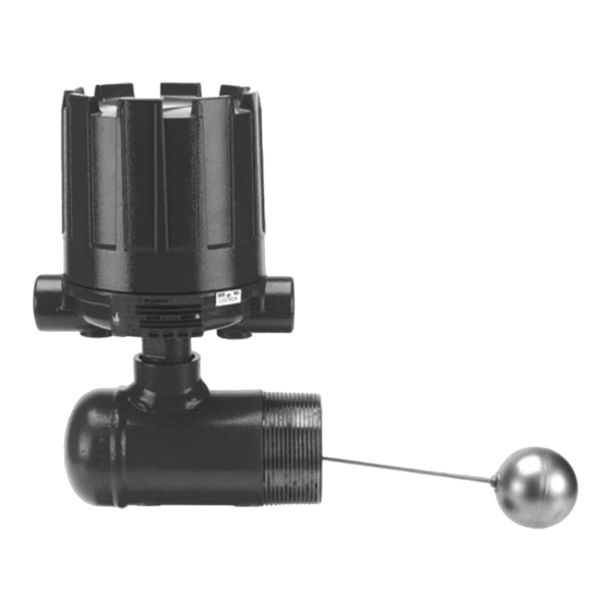
- Page 1 Side mounting T62, T64 and T67 Installation and Operating Manual Liquid Level Switches...
- Page 2 UNPACKING Side mounting liquid level switches are shipped from the factory with the float and float stem removed from the chamber assembly and packed separately in the same container. Unpack the instru- ment carefully. Make sure all components have been removed Nameplate: - part number from the packing material.
- Page 3 WIRING CAUTION: All units are shipped from the factory with the enclosing tube tightened and the switch housing set screw locked to the enclosing tube. Failure to loosen the set screw prior to repositioning the supply and output connections may cause the enclosing tube to loosen, resulting in possible leakage of the process liquid or vapor. NOTE: If control is equipped with pneumatic switch mechanism, disregard these instruction and refer to instruction bul- letin BE 42-685 and BE 42-686 on mechanism furnished for air (or gas) connections.
-
Page 4: Switch Differential Adjustment
SWITCH DIFFERENTIAL ADJUSTMENT The level differential setting of the side mounting controls guide washer can be field adjusted within limits specified in the table at right by repositioning the jam nuts on the magnetic sleeve upper jam nuts stem. NOTE: The control need not be removed from tank or ves- lower sel to make differential adjustment. - Page 5 SWITCH DIFFERENTIAL ADJUSTMENT LEVEL DIFFERENTIAL VS. MOUNTING NOZZLE LENGTH The tables below may be used to determine the maximum level travel (differential) available between “Switch on” and “Switch off” actuations with mounting nozzles of different lengths. The differentials given occur with the minimum tank opening diameter listed for each model and are applicable to standard controls.
-
Page 6: Preventive Maintenance
Certain adjust- ments provided for in Magnetrol controls should not be 2. Inspect switch mechanisms, terminals and connec- attempted in the field. When in doubt, consult the facto- tions regularly ry or your local Magnetrol representative. -
Page 7: Troubleshooting
TROUBLESHOOTING Check complete unit Usually the first indication of improper operation is failure of the controlled equipment to function–pump will not start (or CAUTION: With electrical power "on" care should stop), signal lamps fail to light, etc. When these symptoms be taken to avoid contact with switch leads and occur, whether at time of installation or during routing ser- connections at terminal block. -
Page 8: Agency Approvals
AGENCY APPROVALS AGENCY APPROVED MODEL AREA CLASSIFICATION ATEX All with electric switch mechanism ATEX II 2 G Ex d IIC T6 Gb and housing listed as ATEX Ex d All with electric switch mechanism ATEX II 1 G Ex ia IIC T6 Ga and housing listed as ATEX Ex ia All with electric switch mechanism Class I, Div 1, groups C &... -
Page 9: Specifications
SPECIFICATIONS Float pressure / temperature ratings Max pressure bar (psi) @ 40 °C @ 400 °C @ 480 °C @ 540 °C Model Float size mm (inches) (100 °F) (750 °F) (900 °F) (1000 °F) ø 64 (2.50) 24,1 (350) 19,4 (282) 18,7 (271) 18,5 (268) -
Page 10: Replacement Parts
REPLACEMENT PARTS Partn°: Serial n°: See nameplate, always provide complete partn° and Digit in partn°: 8 9 10 serial n° when ordering spares. X = product with a specific customer requirement ① ② ③ ④ ⑤ ⑥... - Page 11 REPLACEMENT PARTS Switch and housing reference Switch type Bulletin B, C, D, F, R, U, W, X, 8, 9 BE 42-683 BE 42-694 BE 42-798 BE 42-685 BE 42-686 Housing BE 42-683 (1) Enclosing tube kit (contains items 1 & 2) Replacement part Housing type Model (digits 1, 2 &...
- Page 12 SELECTION DATA T62/T64 SINGLE SWITCH A complete measuring system consists of: Order code for T62 models: MODEL NUMBER CODE AND MATERIALS OF CONSTRUCTION Model No. Set points age & process connection Float and trim Magnetic sleeve T62- 400 series SST Carbon steel T62-B 316 SST (1.4401)
- Page 13 SELECT ELECTRIC SWITCH MECHANISM & HOUSING T62-A & T64-A Models T62-B, T62-D & T64-B Models Process ¿ Weather Weather ATEX - IECEx (IP 66) ATEX - IECEx (IP 66) (IP 66) (IP 66) Switch Temperature proof proof Contacts (IP 66) (IP 66) Description Range...
- Page 14 SELECTION DATA T67 DUAL SWITCH A complete measuring system consists of: Order code for T67 models: MODEL NUMBER CODE AND MATERIALS OF CONSTRUCTION Model No. Set points age & process connection Float and trim Magnetic sleeve T67- 400 series SST Carbon steel T67-B 316 SST (1.4401)
- Page 15 SELECT ELECTRIC SWITCH MECHANISM & HOUSING T67-A Models T67-B & T67-D Models Process ¿ Weather Weather ATEX - IECEx (IP 66) ATEX - IECEx (IP 66) (IP 66) (IP 66) Switch Temperature proof proof Contacts (IP 66) (IP 66) Description Range II 2G Ex d IIC T6 Gb II 1G Ex ia IIC T6 Ga NEMA 7/9...
-
Page 16: Service Policy
SERVICE POLICY Owners of Magnetrol products may request the return of a control; or, any part of a control for complete rebuilding or replacement. They will be rebuilt or replaced promptly. Magnetrol International will repair or replace the control, at no cost to the purchaser, (or owner) other than transportation cost if: a.
Need help?
Do you have a question about the AMETEK T62 and is the answer not in the manual?
Questions and answers