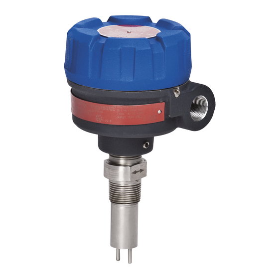
Summarization of Contents
2.0 Installation
2.1 Unpacking
Carefully unpack the instrument, inspect for damage, and report any concealed damage to the carrier.
2.2 Electrostatic Discharge (ESD) Handling Procedure
Follow recommended steps to reduce the risk of component failure due to static electricity.
2.3 Mounting
Instructions for mounting the Thermatel Flow/Level Switches, including orientation and cautions.
2.4 Wiring
Details on connecting power and relay wiring for TD1 and TD2 models, including cautions and notes.
2.5 Setup
Configuration settings for the TD1/TD2, including switch positions and their functions.
2.6 Calibration
Step-by-step guide for calibrating the switch for level detection, including fail-safe settings.
3.0 Reference Information
3.1 Description
Overview of Thermatel TD1/TD2 switches, their applications, and construction materials.
3.2 Theory of Operation
Explanation of how the Thermatel Flow/Level Switch operates using dual-element sensing and RTDs.
3.3 Fault Detection
How the TD1/TD2 switches perform continuous self-diagnostics and indicate faults via LED and mA output.
3.4 Resistance Values
Tables providing expected resistance values for the sensor, referencing figures for pin locations.
3.5 Troubleshooting
Guide to diagnose and resolve common issues with the TD1/TD2 switches based on symptoms and settings.
3.6 Maintenance
Procedures for maintaining the Thermatel switches, including cleaning and probe replacement.
3.8 Replacement Parts
3.8.1 Model TD1
List of replacement parts for the Model TD1, including part numbers and descriptions.
3.8.2 Model TD2
List of replacement parts for the Model TD2, including part numbers and descriptions for various electronic modules.
3.9 Specifications
3.9.1 Performance
Technical specifications for TD1/TD2 performance, including voltage, power consumption, and relay ratings.
3.9.2 Probe
Details on probe materials, tip styles, process connections, and pressure/temperature ratings for various probes.
3.9.3 Physical
– inches (mm)
Dimensional drawings and physical characteristics of the TD1 and TD2 models, including insertion lengths.
3.10 Model Numbers
3.10.1 Model TD1
Breakdown of the model number coding for the TD1, explaining each parameter.
3.10.2 Model TD2
Breakdown of the model number coding for the TD2, detailing power, relay, location, and enclosure options.
3.10.3 Standard Probe
Guide for selecting standard probes, detailing tip styles, materials, connections, and insertion lengths.
3.10.4 High Temperature Probe
Details on selecting high-temperature probes, including tip styles, materials, connections, and insertion lengths.
3.10.5 Low Flow Body
Information on the Low Flow Body model, including material, process connection types, and mounting brackets.
3.10.6 Mini Sensor
Details on the Mini Sensor model, covering body style, material, process connections, and insertion lengths.
3.10.7 Connecting Cable (General Purpose, FM/CSA)
Information on selecting connecting cables in feet or meters for general purpose and FM/CSA applications.


Need help?
Do you have a question about the TD2 Series and is the answer not in the manual?
Questions and answers