Table of Contents
Advertisement
Quick Links
Advertisement
Table of Contents

Subscribe to Our Youtube Channel
Related Manuals for Magnetrol TK1


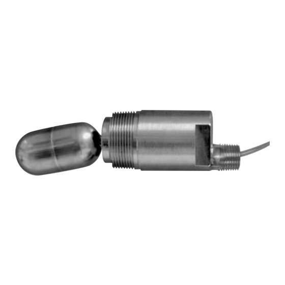
Summary of Contents for Magnetrol TK1
- Page 1 Model TK1 Installation and Operating Manual Side-Mounted Liquid Level loat Switch...
- Page 2 Read this Manual Before Installing Notice of Trademark, Copyright, and Limitations This manual provides information on the Model TK1 Float Magnetrol & Magnetrol logotype are registered trademarks ® ® Level Switch. It is important that all instructions are read of Magnetrol International, Incorporated.
-
Page 3: Installation
Model Number Serial Number Before You Begin Caution: During the installation of Model TK1, the float and pivot area must be kept free of metallic particles that might be attracted to the magnet. Caution: This instrument is intended for use in Installation Category II, Pollution Degree 2. -
Page 4: Threaded Mounting
1.3.2 Flanged Mounting Green Have proper flange bolting and gasket(s) on hand. Carefully align the bolt holes of the TK1 flange with those of the Figure 2 vessel mounting flange. Ensure that the N.O. marking on SPST wiring N.O. position flying leads body is upward for normally opened operation on models with SPST switches. -
Page 5: Preventive Maintenance
ORANGE N.C. N.C. TK1 level switches may sometimes be exposed to excessive heat or moisture. Under such conditions insulation on electri- cal wires may become brittle, eventually breaking or peeling away. The resulting bare wires can cause short circuits. Check... -
Page 6: Reference Information
Figure 7 an electrical circuit. Cross section Troubleshooting The Model TK1 Liquid Level Switch is designed and engi- neered for trouble-free operation. Common problems are discussed in terms of their symptoms and corrective actions as recommended. 3.3.1 External Causes Usually the first indication of improper operation is failure of the controlled equipment to function (e.g., pump will... - Page 7 5. If the complete Model TK1 level switch operates properly when removed from service, check to ensure that liquid is entering the tank or vessel. A closed valve or clogged pipeline may prevent movement of the liquid in the vessel.
- Page 8 Class I, Div 1; Groups C, D TK1-X0XX-BXK Explosion Proof Class II, Div 1; Groups E, F, G TK1-X0XX-BXC Type 4X Installation Category II TK1-X0XX-XXX Low Voltage Directives 2006/95/EC Pollution Degree 2 Per Horizontal Standard: EN 61010-1/1993 & Amendment No. 1 44-608 TK1 Liquid Level Switch...
-
Page 9: Electrical Specifications
Enclosure Rating NEMA 4X/7/9 Class I, Div. 1, Groups C & D Enclosure Material 316/316L stainless steel or cast iron/aluminum Electrical Connection ⁄ " NPT or condulet box(es) with ⁄ " NPT Contact Material Silver cad-oxide 44-608 TK1 Liquid Level Switch... - Page 10 3.5 (89) ➀ 6.5 (165) ➀ 6.5 (165) TK1 with threaded connection and TK1 with flanged connection and SPST or SPDT switch with flying leads SPST or SPDT switch with flying leads ➀ Add 0.75" for models with extended stems.
-
Page 11: Model Numbers
(switch types R & S only) 316 SS with cast iron/aluminum junction box, FM XP √ 316 SS, CSA XP (switch types R & S only) 316 SS with cast iron/aluminum junction box, CSA XP 44-608 TK1 Liquid Level Switch... - Page 12 Service Policy Return aterial Procedure Owners of MAGNETROL controls may request the return So that we may efficiently process any materials that are of a control or any part of a control for complete rebuilding returned, it is essential that a “Return Material or replacement.
Need help?
Do you have a question about the TK1 and is the answer not in the manual?
Questions and answers