Table of Contents
Advertisement
Quick Links
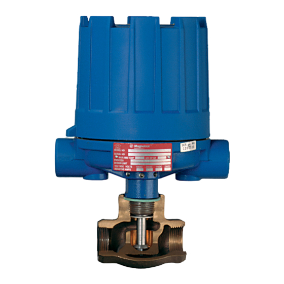
Description
F50 Flow Switches are utilized, in horizontal lines, to sense
the start or stop of liquid flow in oil, chemical, gas, and
water lines.
Principle of operation
The rate of flow through the valve body raises or lowers the
disc. This in turn raises or lowers the magnetic sleeve, with-
in its sealed non-magnetic enclosing tube. On an increasing
flow rate, the magnetic sleeve rises into the field of the per-
manent magnet, located outside the enclosing tube, actuat-
ing the attached switch mechanism. When the flow rate
drops, below the rate for which the flow disc is calibrated, a
reversal of this action occurs.
Operating cycle
On an increasing flow rate, the flow disc moves the attrac-
tion sleeve up within the field of a switch magnet, drawing it
in tightly to the enclosing tube. This causes the switch to
make or break an electrical circuit. When the flow rate
drops, below the rate for which the flow disc is calibrated,
the attraction sleeve is pulled downward until, at a predeter-
mined low flow rate, the switch magnet releases and swings
outward, away from the enclosing tube, causing a reversal
of the switching action.
Mercury switch
No flow
position
Figure 1
F50 Flow Switch
Instruction Manual and Parts List
Pivot
Tension
spring
Swing out
position
Enclosing tube
(Non-magnetic)
Sleeve
Magnet
(magnetic)
Swing in
position
Flow disc
Figure 2
Position with
actuating flow
present
Advertisement
Table of Contents

Subscribe to Our Youtube Channel
Related Manuals for Magnetrol F50


Summary of Contents for Magnetrol F50
- Page 1 F50 Flow Switch Instruction Manual and Parts List Description F50 Flow Switches are utilized, in horizontal lines, to sense the start or stop of liquid flow in oil, chemical, gas, and water lines. Principle of operation The rate of flow through the valve body raises or lowers the disc.
-
Page 2: General Information
1.39 1.10 1.33 1.15 Example: A 2" NPT size Model F50, with size C flow disc, actuates with water flow rates of 5.1 GPM increasing flow 1.27 1.20 and 4.3 GPM decreasing flow. Then, used with a hydrocar- 1.22... - Page 3 Electronic switch mechanism & enclosure Max. Ž NEMA 4X/7/9 Body Pipe Cl I Div. 1 Switch Process Set Point Material Flow Aluminum, Aluminum, Size Description Temp. Rate Polymer (NPT) °F (°C) Enclosure Construction Coated Group B ⁄ " or 1" A thru F Bronze A thru D...
-
Page 4: Installation
INSTALLATION Piping Wiring The Model F50 flow switch should be located in a horizon- CAUTION: Model F50 flow controls are shipped from the tal pipe run, with the arrow on the valve body pointing in the factory with the enclosing tube tightened and the middle direction of flow. -
Page 5: Preventive Maintenance
Certain adjustments mechanisms furnished for service instructions). provided for in F50 controls should not be attempted in d. Controls may sometimes be exposed to excessive the field. When in doubt, consult the factory or your local heat or moisture. -
Page 6: Specifications
(80) Connection size NPT switch with terminal block (both ends) 1.19 (30) Horizontal lines only 3.81 (97) F50 Flow Switch with 1 ⁄ " or 2" NPT Internal Pipe, Bronze or Stainless Steel Body 5.93 (150) 3.87 (98) 6.25 (158) Outline Dimensions 7.94... -
Page 7: Replacement Parts
REPLACEMENT PARTS Bronze Body Stainless Steel Body Item Description " 1" " 2" " 1" " 2" Housing Cover Housing Base Refer to chart below for appropriate bulletin number on switch mechanism and housing replacement assemblies. Switch Mechanism Switch Enclosing Tube 32-6325-002 32-6325-002 E-Tube Gasket... - Page 8 5300 Belmont Road • Downers Grove, Illinois 60515-4499 • 630-969-4000 • Fax 630-969-9489 • www.magnetrol.com 145 Jardin Drive, Units 1 & 2 • Concord, Ontario Canada L4K 1X7 • 905-738-9600 • Fax 905-738-1306 Heikensstraat 6 •...
Need help?
Do you have a question about the F50 and is the answer not in the manual?
Questions and answers