
Related Manuals for Wood-mizer HR250


Summary of Contents for Wood-mizer HR250
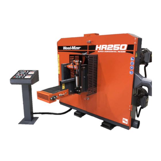
- Page 1 HR250 TWIN HEAD HORIZONTAL BAND RESAW OPERATIONS MANUAL • The operator must thoroughly read this manual before operation. • Keep this manual for future reference. ‘’ORIGINAL INSTRUCTION’’...
- Page 2 MANUFACTURER DETAILS DETAILS Wood-Mizer Asia Manufacturing Co. Ltd No.2, Gongyequ 40 Road, Xitun District Taichung City, 40768 Taiwan R.O.C. Contact Details: Email: info@woodmizerasia.com Tel: +886 4 2359 3022 Tomasz Agaciński / Engineering Manager Responsible for Technical Documentation: Wood-Mizer Industries Sp. z o.o.
- Page 3 CONTENTS...
-
Page 4: General Safety Rules For Woodworking Machinery
GENERAL SAFETY RULES FOR WOODWORKING MACHINERY WARNING Do not attempt to operate until you have read thoroughly and understood completely all instructions, rules etc. contained in this manual. Failure to comply can result in accidents involving fire, electric shock, or serious personal injury. - Page 5 GENERAL SAFETY RULES FOR WOODWORKING MACHINERY 7. Keep children away. All visitors should be kept at a safe distance from the work area. 8. Make workshop childproof. With padlocks, master switches, or by removing starter keys. 9. Do not force the machine. It will do the job better and be safer at the rate for which it was designed.
- Page 6 GENERAL SAFETY RULES FOR WOODWORKING MACHINERY 12. Always use safety glasses. Use face or dust masks if the operation area has too much sawdust. Do not wear general glasses, because they not resist impact. They are not safety glasses. 13. Secure work. 14.
- Page 7 Use a wood dust collection system whenever possible. The HR250 Resaw is intended for sawing wood ONLY. The machine must not be used for other purposes such as cutting ice, metal or any other materials.
- Page 8 SAFETY RULES FOR HORIZONTAL BAND RESAW 1. Do not attempt to remove any object from the conveyor belt when the machine is running. 2. The sawblade is very sharp. Care should be taken when replacing the sawblade. 3. Turn the power off before performing maintenance or servicing.
- Page 9 SAFETY RULES FOR HORIZONTAL BAND RESAW 11. Make sure the machine is properly ground to avoid the danger of electric shock. 12. Before feeding wood into the machine, check if it contains nails or metallic objects or not. Never clean the blade or blade wheels with a brush or a scraper during sawmill operation.
- Page 10 BAND RESAW Use recommended ancillary equipment. If ancillary equipment is removed the original guards or safety devices shall be replaced. Wood-Mizer and our authorized agency are responsible for a future connection of the machine with ancillary equipment only if we ourselves have designed such connection.
- Page 11 EMERGENCY RELEASE OF TRAPPED PERSON 1. All persons not trained in the operation or safety functions of the machine should be allowed within proximity of the machine. 2. The machine has four “Emergency Stop” buttons located on the infeed and outfeed of the machine.
-
Page 12: Safety Labels
SAFETY LABELS Safety Labels Description See Table 1-1. Pictogram decals used to warn and inform the user about danger in the saw... - Page 13 SAFETY LABELS...
- Page 14 SAFETY LABELS...
- Page 15 SAFETY LABELS...
-
Page 16: Machine Specifications
MACHINE SPECIFICATIONS... - Page 17 MACHINE SPECIFICATIONS...
- Page 18 MACHINE SPECIFICATIONS...
- Page 19 MACHINE SPECIFICATIONS...
- Page 20 MACHINE SPECIFICATIONS Noise Level = 87dB(A) The noise level measurement was taken in accordance with PN-EN ISO 3746 Standard. The noise exposure level given above concerns an 8-hour workday. Value for associated uncertainty K=4dB. The figures quoted are emission levels and are not necessarily safe working levels. Whilst there is a correlation between the emission and exposure levels, this cannot be used reliably to determine whether or not further precautions are required.
- Page 21 SAWDUST EXTRACTION SPECIFICATIONS SAWDUST EXTRACTOR SPECIFICATION Air flow required: 1200m Collector Inlet Diameters (in front of fan): 150 mm Electric Motor Horsepower: 1,5 kW Number of Sacks for Waste 2 pc Total Capacity of Sacks 0.25 m Pressure drop connection outlet: 1,5 kPa (0.22 psi) Weight 110 kg...
- Page 22 SAWDUST EXTRACTION SPECIFICATIONS Top dust extraction chute Bottom dust extraction chute...
- Page 23 This machine should be lifted or moved only by using a forklift. Make sure the loading capacity of the forklift is enough to lift the machine. The weight of the HR250 is shown as below: Net weight: 1630Kg Gross weight: 1835Kg Lifting a packed machine and unpacked machine is shown below.
-
Page 24: Unpacking And Checking Contents
UNPACKING AND CHECKING CONTENTS The twin head horizontal band resaw is shipped in one wooden crate. Carefully unpack the machine to avoid damage to the machine. Check the machine to see if all parts are present and free of damage (Please refer to the Legend of the Machine, pages 22 and 23). -
Page 25: Cleaning The Machine
CLEANING THE MACHINE Before shipment, the machine is coated with a rust- preventive oil to prevent rusting during transportation. Once you receive and unpack the machine, thoroughly remove rust preventive oil. To do this, use a clean cloth soaked in kerosene for removing the rust preventive oil. CAUTION Do not use lacquer thinners or any solvents, because they can damage the... -
Page 26: Installing Machine
• A concrete foundation and anchored bolts are recommended. • When your HR250 resaw is used indoors, it must be operated with a sawdust exhaust system connected. • The HR250 resaw must not be used outdoors when it is raining/snowing. - Page 27 INSTALLING MACHINE The following electrical requirements are HIGHLY recommended for safe electrical installation: • Supply voltage: 0.9 - 1.1 nominal supply voltage • Source frequency: 0.99 - 1.01 nominal frequency • Ambient temperature: 5°C - 40°C. • Altitude: shall be at altitudes up to 1000m above mean sea level. •...
- Page 28 INSTALLING MACHINE Please see below WORKSTATIONS OR SAFE STANDING for three operators while operating the machine.
- Page 29 LEGEND OF THE MACHINE (FRONT VIEW) 1. Feed conveyor 2. Air cylinder for infeed pressure roller 3. Lifting channels for forklift 4. Front door 5. Dust outlet for lower sawblade (ø6”) 6. Lower saw wheel drive motor (20HP) 7. Dust outlet for upper sawblade (ø6”) 8.
- Page 30 LEGEND OF THE MACHINE (BACK VIEW) 1. Lower saw wheel drive motor (20/ 25HP) 2. Filter/regulator/lubricator combination unit 3. Air/hydraulic combination unit for sawblade tension 4. Emergency stop switch 5. Conveyor belt drive motor (2HP) 6. Gear reducer 7. Oil box for oil mist cooler 8.
-
Page 31: Control Panel
CONTROL PANEL 1. KEY SWITCH- MAINTENANCE/ RUN 2. POWER ON SWITCH 3. EMERGENCY STOP SWITCH 4. CONVEYOR BELT SPEED REGULATOR 5. SAWBLADE TENSION SWITC 6. AIR PRESSURE WARNING LIGHT 7. CONVEYOR BELT STOP SWITCH 8. CONVEYOR BELT START SWITCH... - Page 32 CONTROL PANEL 9. LOWER SAW WHEEL STOP SWITCH 10. LOWER SAW WHEEL START SWITCH 11. LOWER SAW WHEEL LOWERING SWITCH 12. LOWER SAW WHEEL RAISING SWITCH 13. DIGITAL CONTROLLER FOR LOWER SAW WHEEL ELEVATION 14. DIGITAL CONTROLLER FOR UPPER SAW WHEEL ELEVATION 15.
- Page 33 CONTROL PANEL...
- Page 34 CONTROL PANEL...
- Page 35 CONTROL PANEL...
- Page 36 CONTROL PANEL...
- Page 37 CONTROL PANEL...
- Page 38 CONTROL PANEL...
- Page 39 CONTROL PANEL...
- Page 40 CONTROL PANEL...
- Page 41 CONTROL PANEL (MODEL CH-525) 1) FIGURE BUTTONS ARE FROM 0 TO 9. 2) BUTTON C IS FOR CLEAR. 3) (.) BUTTON FOR SETTING THE DIGITS AT RIGHT SIDE OF THE DECIMAL POINT. 4) SET IS A BUTTON FOR SETTING DATA. 5) UNIT IS A BUTTON FOR TRANSITING BETWEEN INCHES AND MM.
- Page 42 CONTROL PANEL 6) (–) FOR MANUAL OPERATION TO DEDUCT THE FIGURE. 7) (+) FOR MANUAL OPERATION TO INCREASE THE FIGURE. 8) ‘’START’’ IS A BUTTON TO START. 9) ‘’STOP’’ IS A BUTTON TO STOP AND STOP ALL OPERATIONS MEANWHILE. OPERATING INSTRUCTION FOR CORRECTING DATA In accordance with the dimension of the actual material, press “SET”...
- Page 43 CONTROL PANEL STEP 1: Press ‘’SET’’ button, take your finger off the ‘’SET’’ button and 0 will show on the display STEP 2: Press ‘’1’’ button followed by pressing ‘’0’’ button twice. STEP 3: Press ‘’SET’’ button and hold for 2-3 seconds. Figure 100.0 will be displayed. Correcting the data is complete.
- Page 44 CONTROL PANEL DIMENSION UNIT SELECTING & DESCRIPTION OF CHANGE The user can choose between INCH and MM in accordance with their common use. This control unit can change the dimension units swiftly by pressing the “UNIT” button. A light will indicate on the top left corner which unit is currently selected.
- Page 45 CONTROL PANEL Current figure shown is 100.0 STEP 1: Press ‘’SET’’ button. Display will show 0. STEP 2: Press ‘’2’’ button, followed by pressing ‘’0’’ button twice. Display will show 200.
- Page 46 CONTROL PANEL STEP 3: Press ‘’START’’ button. The control unit starts to run and the figure on the display changes Back to 100 and begins to increase until it reaches the set size. Problem Search for Failure Correction The display fails to show Inspect incoming voltage, Make sure wires are secure, figures.
- Page 47 LAYOUT OF VARIOUS LIMIT SWITCHES LIMIT SWITCH FOR MIN. DISTANCE BETWEEN SAWBLADES 1. This limit switch is located at the right side of the machine back, which is used to control the minimum distance between the upper and the lower sawblades. 2.
- Page 48 LAYOUT OF VARIOUS LIMIT SWITCHES These 3 limit switches are provided at the right side of the machine back. 1. LIMIT SWITCH FOR LOWER SAW WHEEL POSITION FOR BLADE LOOSENING (1) When performing sawblade loosening on lower saw wheels, this limit switch is used to prevent the lower saw wheel from colliding against the conveyor table.
- Page 49 LAYOUT OF VARIOUS LIMIT SWITCHES...
- Page 50 CONNECTING POWER WIRES CAUTION It is recommended that a 30mA Ground Fault Interrupter (GFI) be used. 1. Before connecting the power wires of the machine to your factory’s power source, make sure the voltage, Hz and phase of the machine are same as that of your factory’s power source.
- Page 51 ELECTRIC WIRE DIAGRAM...
- Page 52 ELECTRIC WIRE DIAGRAM...
- Page 53 ELECTRIC WIRE DIAGRAM...
- Page 54 ELECTRIC WIRE DIAGRAM...
- Page 55 ELECTRIC WIRE DIAGRAM...
- Page 56 ELECTRIC WIRE DIAGRAM...
- Page 57 ELECTRIC WIRE DIAGRAM...
- Page 58 ELECTRIC WIRE DIAGRAM...
- Page 59 ELECTRIC WIRE DIAGRAM...
- Page 60 ELECTRIC WIRE DIAGRAM...
- Page 61 ELECTRIC WIRE DIAGRAM...
- Page 62 ELECTRIC WIRE DIAGRAM...
- Page 63 ELECTRIC WIRE DIAGRAM...
- Page 64 CONNECTING THE DUST HOOD OUTLET 1. This machine is equipped with three dust hood outlets. Two are located at the right side of the machine, and one is located at the left side. 2. Diameters of all dust hood outlets are all 6". 3.
- Page 65 CONNECTING THE AIR CIRCUIT 1. The quick air connector is provided on the filter/regulator/lubricator combination unit (F.R.L. Unit). 2. You need to connect the quick air connector to an air source. 3. The size of the quick air connector is 3/8”. 4.
- Page 66 PNEUMATIC/ HYDRAULIC DIAGRAM...
- Page 67 FILTER/ REGULATOR/ LUBRICATOR OIL (Turbine oil ISO-VG32) UNIT 1. PRESSURE GAUGE. The pressure for the air system is indicated on the pressure gauge. Working air pressure can be adjusted by turning the pressure regulation knob located on the filter cup. Turn it clockwise for increasing pressure.
- Page 68 OIL MIST COOLER 1. This machine is equipped with an oil mist cooler for cooling the upper and the lower sawblades. In addition, the cooler can also remove dusts deposited on the sawblade. 2. The oil mist cooler requires air and oil to operate. 3.
- Page 69 ADJUSTING OIL MIST FLOW RATE 1. Open the front doors before adjusting oil mist flow rate. 1. Adjusting the oil mist flow rate is made only when the machine is fully stopped. 2. The upper and lower sawblade are cooled through individual nozzles. 3.
- Page 70 INSPECTING AND ADJUSTING SAWBLADE TENSION When installing a new sawblade, it is necessary to inspect and adjust the sawblade tension. In addition, after the machine has operated for a long period, the sawblade tension may become loose gradually. Currently, it is also necessary to inspect and adjust the sawblade tension.
- Page 71 INSPECTING AND ADJUSTING SAWBLADE TENSION 2. Fit the sawblade tension gauge onto the sawblade. Make sure the two slot bottoms on the sawblade tension gauge have touched the back side of the sawblade. 3. First tighten the left fix screw on the sawblade tension gauges. 4.
- Page 72 INSPECTING AND ADJUSTING SAWBLADE TENSION 5. Tighten the right fix screw on the sawblade tension gauge 6. Turn the gauge to set it at graduation "0." 7. Turn the sawblade tension switch (5), located on the operation panel, to the Right position (tighten) for tightening the sawblade.
- Page 73 INSPECTING AND ADJUSTING SAWBLADE TENSION 9. If adjusting blade tension is required, turn the air pressure regulator on the air hydraulic combination unit, located at the back side of the machine. 10. Turn this air pressure regulator clockwise for increasing pressure, which will tighten the sawblade tension.
- Page 74 ADJUSTING SAWBLADE TRACK (FORWARD/ BACKWARD DIRECTION) 1. Turn power off before conducting sawblade tracking adjustment. 2. Open the saw wheel guard (front doors). 3. Make sure the sawblade tension is proper before adjusting sawblade tracking. 4. Slowly turn the saw wheel by hand, and check the sawblade running track condition.
- Page 75 ADJUSTING SAWBLADE TRACK (FORWARD/ BACKWARD DIRECTION) 6. Turn the blade track adjustment screw 1/4 turn counter- clockwise for moving the sawblade forward. Turn the screw1/4 turn clockwise for moving the sawblade backward. 7. After blade track is adjusted, tighten the fixing nut (1). 8.
- Page 76 ADJUSTING SAWBLADE TRACK (RIGHT/ LEFT DIRECTION) 1. Turn power off before conducting sawblade tracking adjustment. 2. Open the saw wheel guard (front doors). 3. Make sure the sawblade tension is so proper before adjusting sawblade tracking. 4. Slowly turn the saw wheel by hand, and check the sawblade running track condition.
- Page 77 ADJUSTING SAWBLADE TRACK (RIGHT/ LEFT DIRECTION) 6. Turn the blade track adjustment screw 1/4 turn counter- clockwise for moving the sawblade leftward. Turn the screw 1/4 turn clockwise for moving the sawblade rightward. 7. After blade track is adjusted, tighten the fixing nut (2). 8.
- Page 78 ADJUSTING CONVEYOR BELT TRACKING 1. If the conveyor belt runs to either right or left side, you need to adjust the conveyor belt running track. 2. Before adjusting the conveyor belt tracking, make sure the conveyor belt tension is tightened. Otherwise, you should adjust belt tension before adjusting its running track.
-
Page 79: Blade Guide Alignment
BLADE GUIDE ALIGNMENT 1. By loosening bolts you can now adjust the height of the guide plates, it is important to make sure the guide plates both top and bottom are equally spaced from the blade. It is recommended that the correct shims be installed according to the current blade thickness being used to ensure there is space for the blade between the guide plates. - Page 80 BLADE GUIDE ALIGNMENT 3. Once you are happy with the adjustment of the blade guides you can move the blade guide block forward or backwards by loosening bolts 3. (This is dependent on the blade width you are using) Try keep a 3mm gap from the gullet of the blade to the edge of the guide plate.
- Page 81 CHANGING SHIMS/ REPLACING GUIDE PLATES...
- Page 82 ADJUSTING THE LOADING PRESSURE OF INFEED PRESSURE ROLLER The loading (hold-down) pressure and raising sensitivity of the indeed pressure roller can be adjusted by turning the two air flow regulators, provided on the air cylinder located at the infeed end. The “UPPER AIR FLOW REGULATOR “is used to adjust the hold- down pressure of the infeed pressure roller.
- Page 83 CONVENIENT TIMBER INFEED The infeed roller assembly is equipped with a sensing plate. Once the wood touches the sensing plate, the infeed roller assembly will raise slowly. This allows the wood to be pressed by the infeed roller easily without blocking problems.
-
Page 84: Maintenance
MAINTENANCE Proper maintenance is important to keep the machine in the best condition. Note that a small problem may lead to poor machine performance or even cause a serious damage. Therefore, the operator and maintenance personnel should not neglect the maintenance work CAUTION Disconnect air supply and release compressed air from the air system before servicing... -
Page 85: Daily Maintenance
MAINTENANCE 2. DAILY MAINTENANCE (1) Every day before starting the machine, check all lubrication positions of the machine. (2) Every day when the work is finished, clean the machine. Remove wood chips from the machine and surroundings. Apply oil on the sliding parts. Turn power off. (3) During operation, if any abnormal noise occurs, stop machine operation immediately. -
Page 86: Weekly Maintenance
MAINTENANCE 3. WEEKLY MAINTENANCE (1) Clean the filter screen and fan in the electrical cabinet. (2) Clean the entire machine and the working area. (3) Check if any switch or push-button has loosened or not. If loosened, tighten securely. (4) Check if warning devices and proximity sensors work normally on not. Inspect all safety systems to ensure all functioning correctly. - Page 87 MAINTENANCE 4. AFTER FIRST WEEK OF USE After the first week of running, it is important to tension up the main wheel bearings to ensure that there is not a lot of play (Loose) on the bearing that can potentially destroy the bearing and wheel shaft. Remove wheel hub screws and wheel hub.
- Page 88 MAINTENANCE 5. HALF-YEAR MAINTENANCE (1) Check if air source pressure is set in the normal range. (2) Check home positions of various mechanisms. (3) Check positioning accuracy and gear backlash. Check blade wheel tracking and aligning. Change blade guide plates if not changed yet. Check drive belts and possibly replace.
-
Page 89: Yearly Maintenance
(1) Inspect machine accuracy. If necessary, make adjustment. (2) Inspect leveling accuracy. (3) Check if all switches and pushbuttons work normally or not. Safety devices on the HR250 resaw which must be checked before every shift: • E-STOP button and its circuit inspection • Up/down limit switches •... - Page 90 MAINTENANCE Blade cover safety switch and its circuit inspection Turn on the blade motor. Try to open the blade covers. They should not open. Stop the blade motor. Open the blade cover. Try to start the blade motor. The motor should not start.
- Page 91 MAINTENANCE 7. DC ELECTROMAGNETIC BRAKE (CE ONLY) Design and principle of operation The DC electromagnetic brake type H consists of 3 main subassemblies: - electromagnet (1), - armature complete (2) - cast iron fan (3). Electromagnet (1) energized: The DC voltage from the motor applied via the rectifying circuit causes the attraction of the armature (2) releasing the brake and thus the fan (3) is free to rotate.
- Page 92 MAINTENANCE Service During normal operation and at the routine inspections verify the air gap and check if all screws are tight. In case when any symptoms of inefficient braking are observed, then use the self-locking nut (8) to re-adjust the air gap to the value corresponding to Table 1. Such readjustment may be repeated until the brake linings are completely worn out.
-
Page 93: Troubleshooting
TROUBLE SHOOTING... -
Page 94: Serial Plate
SERIAL PLATE... - Page 95 EC declaration of conformity according to EC Machinery Directive 2006/42/EC, Annex II, 1.A Manufacturer: Wood-Mizer Asia Manufacturing Co. Ltd No.2, Gongyequ 40 Road, Xitun District Taichung City, 40768 Taiwan R.O.C. This declaration of conformity is issued under the sole responsibility of the manufacturer.
Need help?
Do you have a question about the HR250 and is the answer not in the manual?
Questions and answers