Table of Contents
Advertisement
Quick Links
Advertisement
Table of Contents

Related Manuals for Wood-mizer HR115


Summary of Contents for Wood-mizer HR115
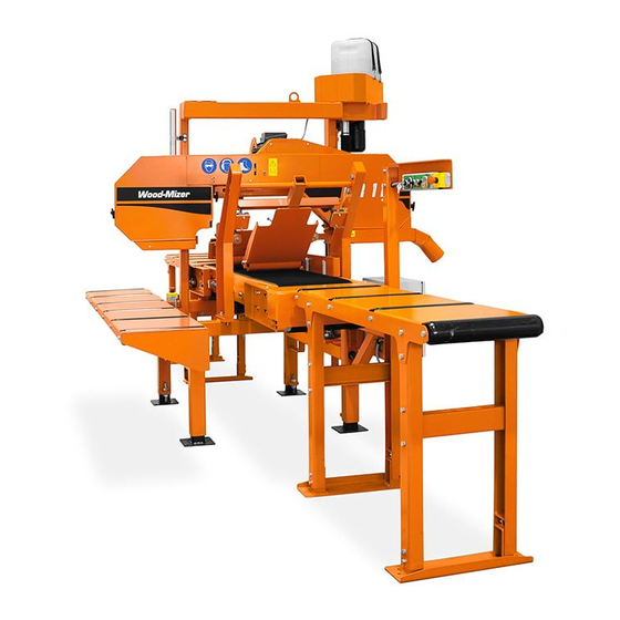
- Page 3 Horizontal Resaw HR115 Wood-Mizer ® Safety, Setup, Operation & Maintenance Manual HR115, HR115 EC, HR115 W rev.A3.03 Safety is our #1 concern! Read and understand all safety information and instructions before oper- ating, setting up or maintaining this machine. Form #924...
-
Page 4: Table Of Contents
Table of Contents Section-Page General Contact Information Branches & Authorized Sales CentersWood-Mizer Locations (North and South America) SECTION 1 SAFETY Safety Symbols..................1-1 Safety Instructions ..................1-2 Observe Safety Instructions Wear Safety Clothing Keep Resaw And Area Around Resaw Clean Dispose Of Sawing By-Products Properly Check Resaw Before Operation Keep Persons Away Keep Hands Away... - Page 5 Table of Contents Section-Page SECTION 4 ALIGNMENT Pre-Alignment Procedures..............4-1 Preparing The Machine For Alignment..........4-1 Blade Installation and Alignment............4-1 Blade Wheel Alignment .................4-2 Aligning The Blade Guides ..............4-6 Blade Deflection..................4-6 Blade Guide Vertical Tilt Adjustment............4-7 Blade Guide Spacing ................4-8 Horizontal Tilt Adjustment..............4-10 4.10 Motor Drive Belt Adjustment...............4-11 4.11...
- Page 6 From Europe call our European Headquarters and Manufacturing Facility in Kolo-Poland, Nagorna 114 St., at +48-63-2626000. Please have the vehicle identification number and your customer number ready when you call. Wood-Mizer will accept these methods of payment: Visa, Mastercard, or Select Purchase ...
-
Page 7: General Contact Information
Getting Service Wood-Mizer is committed to providing you with the latest technology, best quality and strongest customer service available on the market today. We continually evaluate our customers’ needs to ensure we’re meeting current wood-processing demands. Your comments and suggestions are welcome. -
Page 8: Branches & Authorized Sales Centerswood-Mizer Locations (North And South America)
Branches & Authorized Sales CentersWood-Mizer Locations (North and South America) EUROPE UNITED STATES European Headquarters World Headquarters Wood-Mizer Industries Sp. z o.o. Wood-Mizer LLC Nagórna 114, 62-600 Koło, Poland 8180 West 10th Street Tel.: +48-63-26-26-000 Indianapolis,Indiana 46214-2400, Fax: +48-63-27-22-327 www.woodmizer.eu Tel.: +1-317-271-1542... - Page 9 CROATIA Krešimir Pregernik ITALY Pasquale Felice SERBIA Dragan Markov Pregimex d.o.o. Wood-Mizer Italia Srl Wood-Mizer Balkan d.o.o. S. Batušiæa 31, 10090 Zagreb Cda. Capoiaccio SN Svetosavska GA 3/3; P. Fah 25 Tel.:/Fax: +3851-38-94-668 86012 Cercemaggiore 23 300 Kikinda Krešimir Pregernik Campobasso Tel.:/Fax: +381-230-25-754...
- Page 10 Robert Moxham Arnborgvej 9, 7330 Brande- Fasterholt TRANSILVANIEI Nr. 5 Regional Direction - Asia Tel.: +45-971-88-265 Sibiu, Cisnadie 555300 Wood-Mizer Asia Manufacturing Co., Ltd. Fax: +45-971-88-266 Tel.:/Fax: : +40-369-405-433 No.2, Gongyequ 40th Rd. Xitun District, Brian Jensen GSM: +40-745-707-323 Taichung City, 40768, Taiwan, R.O.C.
-
Page 11: Safety
Safety Safety Symbols SECTION 1 SAFETY Safety Symbols The following symbols and signal words call your attention to instructions concerning your personal safety. Be sure to observe and follow these instructions. DANGER! indicates an imminently hazardous situation which, if not avoided, will result in death or serious injury. WARNING! suggests a potentially hazardous situation which, if not avoided, could result in death or serious injury. -
Page 12: Safety Instructions
Wood-Mizer resaw. All Wood-Mizer resaw owners are encouraged to become thoroughly familiar with these applicable laws and comply with them fully while using the machine. -
Page 13: Wear Safety Clothing
Safety Wear Safety Clothing Wear Safety Clothing WARNING! Secure all loose clothing and jewelry before operating the resaw. Failure to do so may result in serious injury or death. WARNING! Always wear gloves and eye protection when handling bandsaw blades. Changing blades is safest when done by one person! Keep all other persons away from area when coiling, carrying or changing a blade. -
Page 14: Check Resaw Before Operation
Safety Check Resaw Before Operation Check Resaw Before Operation DANGER! Make sure all guards and covers are in place and secured before operating the resaw. Failure to do so may result in serious injury. Keep Persons Away DANGER! Keep all persons out of the path of moving equipment and lumber when operating the resaw. -
Page 15: Keep Hands Away
Safety Keep Hands Away Keep Hands Away DANGER! Always shut off the blade motor before changing the blade. Failure to do so will result in serious injury. DANGER! Motor components can become very hot during operation. Avoid contact with any part of a hot motor. Contact with hot motor components can cause serious burns. -
Page 16: Use Proper Maintenance Procedures
Safety Use Proper Maintenance Procedures Use Proper Maintenance Procedures DANGER! Make sure all electrical installation, service and/or maintenance work is performed by a qualified electrician and is in accordance with applicable electrical codes. DANGER! Hazardous voltage inside the electric boxes and at the motor can cause shock, burns, or death. -
Page 17: Keep Safety Labels In Good Condition
Safety Keep Safety Labels In Good Condition CAUTION! Always wear gloves when handling the blade. Never grab the blade with bare hands! CAUTION! If the blade breaks during machine operation, push the EMERGENCY STOP button to stop the blade motor and wait 10 seconds before you open the blade housing cover. - Page 18 Safety Keep Safety Labels In Good Condition TABLE 1-1 099220 CAUTION! Close all guards and covers before starting the machine. 099220 099219 Blade tension. Turning the bolt clockwise will increase the blade tension and turning the bolt counterclockwise will decrease the tension.
- Page 19 Safety Keep Safety Labels In Good Condition TABLE 1-1 099540 CAUTION! Gear danger – keep a safe distance away! 099540 096316 Do not open or close the electric box when the switch is not in the ”0” position. 096319 Disconnect power supply before opening the box.
- Page 20 Safety Keep Safety Labels In Good Condition TABLE 1-1 096321 Blade movement direction S12004G CAUTION! Always wear safety goggles when operating the machine! S12005G CAUTION! Always wear protective ear muffs when operating the machine! 501465 CAUTION! Always wear safety boots when operating the machine 501467 Lubrication Point...
- Page 21 Safety Keep Safety Labels In Good Condition TABLE 1-1 P11789 Aligning the blade on the wheels 510643 Setting the blade tension indicator 510643 1015-1088 70-75 1088-1160 75-80 80-85 1160-1233 P85070 CE safety certification 099401 Russian safety certification 099401 S20097 Motor rotation direction S20097 Safety HRdoc062321...
- Page 22 Safety Keep Safety Labels In Good Condition TABLE 1-1 P85066 Blade tracking adjustment 3-4 mm P85066 1-12 HRdoc062321 Safety...
-
Page 23: Operation
Operation Control Overview SECTION 2 OPERATION Control Overview 1. Control Panel See Figure 2-1. The control panel includes switches to start and stop the feed track and the saw head. EMERGENCY “0” “0” STOP START STOP STOP FIG. 2-1 CONTROL PANEL COMPONENTS 2. - Page 24 Operation Control Overview 4. Feed Track Speed Adjustment The feed track speed switch controls the speed at which the feed track moves. Turn the switch clockwise to increase the speed, counterclockwise to reduce the speed. 5. Key Switch The key switch has three positions: “0”...
-
Page 25: Resaw Setup
Operation Resaw Setup Resaw Setup IMPORTANT! Before starting to use the machine you have to meet the following conditions: Set up the machine on firm, level ground and level the machine. Secure the machine to the ground to prevent moving during operation. A concrete foundation or pads (rated to support 31 T/m at each machine foot position) and 16mm anchored bolts are recommended. - Page 26 Operation Resaw Setup Have a qualified electrician install the power supply (according to EN 60204 Standard). The power supply must meet the specifications given in the table below. 3-Phase Fuse Suggested Wire Size Volts Disconnect 400 VAC 16 A 2,5 mm to 15m length TABLE 2-0...
-
Page 27: Replacing The Blade
Operation Replacing The Blade Replacing The Blade DANGER! Always shut off the resaw motor before changing the blade. Disconnect the power supply using the main switch. Failure to do so may result in serious injury. WARNING! Always wear gloves and eye protection whenever handling bandsaw blades. -
Page 28: Tensioning The Blade
Operation Tensioning The Blade Close the blade housing cover. Next, turn the tension handle until the blade is tensioned correctly. Tensioning The Blade See Figure 2-3. Turn the blade tension handle clockwise until the tension gauge indicates the recommended tension. Check the blade tension occasionally when adjusting the cant control or while cutting. -
Page 29: Tracking The Blade
Operation Tracking The Blade See Table 2-1. The recommended tension for different blades is shown below. Blade Type Blade Dimensions Tension range Width (mm) Height (mm) 1.07 1015-1088 70-75 1.14 1088-1160 75-80 2735 1.07 1160-1233 80-85 TABLE 2-1 Tracking The Blade 1. - Page 30 Operation Tracking The Blade See Figure 2-5. To adjust where the blade travels on the blade wheels, use the cant control bolt. Cant Control Bolt FIG. 2-5 If the blade is too far out, back the blade onto the wheel by turning the cant control counterclockwise.
-
Page 31: Tilt Adjustment
Operation Tilt Adjustment Tilt Adjustment See Figure 2-6. The saw head may be tilted to produce siding. Loosen the locking bolt. Turn the tilt adjustment screw clockwise to tilt the saw head upward or counterclockwise to tilt the saw head downward. Tilt Adjustment Screw Locking Bolt FIG. -
Page 32: Up/Down Operation
Operation Up/Down Operation Up/Down Operation 1. Install a blade, if needed, and check for correct blade tension. Use the up and down buttons shown below to raise or lower the cutting See Figure 2-7. head To raise the saw head press up button. -
Page 33: Blade Guide Roller Brackets
Operation Blade Guide Roller Brackets Blade Guide Roller Brackets The machine is equipped with two kinds of blade guide roller brackets: constant inversion - three possible positions, depends on log width. See Figure 2-8. Constant Blade Guide Inversion Blade Guide Hr0074 Roller Bracket Roller Bracket... -
Page 34: Machine Start
Operation Machine Start Machine Start DANGER! Before starting the resaw, perform these steps to avoid injury and/or damage to the equipment: Close the blade housing cover and replace any guards removed for service. Check the feed track and remove all loose objects such as tools, wood, etc. ... - Page 35 Operation Machine Start See Figure 2-10. After the saw head has been successfully started, the feed track can be EMERGENCY “0” “0” STOP START STOP STOP FIG. 2-10 started. To start the track chain motor, turn the Track Start switch (shown in Figure 2-6) left to start the track forward, turn the switch right to start the track backward.
- Page 36 Operation Machine Start EMERGENCY “0” “0” STOP START STOP STOP FIG. 2-12 Factors that will determine what feed rate you can use include: Width of material to be cut. Eight-inch material will require a slower feed rate than 1" material.
-
Page 37: Blade Height Scale
Operation Blade Height Scale 2.10 Blade Height Scale See Figure 2-13. The blade height scale is mounted on the vertical mast. It includes: a blade height indicator centimeter scale (or quarter inch scale) Scale Blade Height Indicator 150028C FIG. - Page 38 Operation Blade Height Scale The Quarter Scale See Table 2-2. The quarter scale contains of four sets of marks. Each set represents a specific lumber thickness. Saw kerf and shrinkage allowance are included, but actual board thickness will vary slightly depending on blade thickness and tooth set. To choose which scale to use, determine what finished thickness you want to end up with.
-
Page 39: Water Lube Operation
Operation Water Lube Operation 2.11 Water Lube Operation See Figure 2-14. The Water Lube System keeps the blade clean. Water flows from a 5-gallon (18.9 liter) bottle through a hose to the blade guide where the blade enters the log. A valve in the bottle cap controls the amount of water flow. A stream of water flows to the blade only when the main motor is turned on. -
Page 40: Operation Procedure
Operation Operation Procedure 2.12 Operation Procedure 1. Install a blade if necessary. WARNING! Always wear gloves and eye protection when handling bandsaw blades. Changing blades is safest when done by one person! Keep all other persons away from area when coiling, carrying or changing a blade. Failure to do so may result in serious injury. - Page 41 Operation Operation Procedure 11. Place the test material on the feed track and start the feed track. DANGER! Always be aware of and take proper protective measures against rotating shafts, pulleys, fans, etc. Always stay a safe distance from rotating members and make sure that loose clothing or long hair does not engage rotating members resulting in possible injury.
-
Page 42: Maintenance
Maintenance Wear Life SECTION 3 MAINTENANCE This section lists the maintenance procedures that need to be performed. The Short Interval Maintenance Schedule lists procedures that need to be performed every 4, 8 or 25 hours.The Maintenance Log lists procedures that need to be performed every 50, 100, 200, or 1000 hours. Keep track of machine maintenance by filling in the machine hours and the date you perform each procedure. -
Page 43: Miscellaneous Lubrication
Maintenance Miscellaneous Lubrication Miscellaneous Lubrication 1. Lubricate the tensioner screw with a rolling bearing grease (e.g. ŁT4S or Shell Extreme Pressure Grease) as needed. See Figure 3-1. Grease Tensioner Threads FIG. 3-2 Blade Wheel Belts 1. Rotate the blade wheel belts and check them for wear. Rotating the belts every 50 hours will give you longer belt life. -
Page 44: Up/Down System
Maintenance Up/Down System Up/Down System 1. Remove any sawdust buildup from the up/down screw bellows, the up/down screw nut, the upper and lower limit switches and the lower bearing housing. See Figure 3-3. Upper Limit Up/Down Switch Screw Bellows Lower Limit Switch Lower Bearing Housing... - Page 45 Maintenance Up/Down System 3. Check the up/down belt tension after the first 20 hours of operation and every 100 hours thereafter. See Figure 3-5. Unbolt the up/down top guard. Loosen the motor mounting bolts. Use the adjustment bolt the top guard. shown below to adjust the belt tension.
-
Page 46: Miscellaneous Maintenance
Maintenance Miscellaneous Maintenance Electromagnet body Coil Armature Brake disk Gear wheel Mounting disk Spring Thrust pin 10. Mounting bolt 11. Adjusting bolt 12. Brake casing 13. Manual release lever 14. Locking element 15. Mounting holes ADJUSTMENT OF AIR GAP The air gap ,,a" grows gradually larger in consequence of wear of brake disc lining (5). The niminal value of the air gap a nom "... -
Page 47: Drive Belt Adjustment
Maintenance Drive Belt Adjustment 4. Check the power feed system steel cable every 50 hours, replace it every 500 hours. Drive Belt Adjustment WARNING! Do not for any reason adjust the drive belts with the engine/motor running. Doing so may result in serious injury. Check the drive belt tension after the first 20 hours, and every 50 hours thereafter. -
Page 48: Safety Devices Inspection
Maintenance Safety Devices Inspection Safety Devices Inspection HR115 – Safety Devices Inspection Safety devices on the HR130 resaw which must be checked before every shift: E-STOP button and its circuit inspection Red safety button inspection Inspection of the control circuits with the E-STOP button pressed ... - Page 49 Maintenance Safety Devices Inspection Turn on the blade motor. The motor should be started; Release the safety button. The blade motor should be stopped. Try to start the motor without pressing the safety button. The blade motor should remain stopped. ...
-
Page 50: Alignment
Alignment Pre-Alignment Procedures SECTION 4 ALIGNMENT Pre-Alignment Procedures Periodically check the machine alignment and adjust if necessary. This chapter explains how to align the entire machine. Care should be taken in performing these steps. Machine alignment determines the accuracy and squareness of your cuts. The machine alignment steps are: 1. -
Page 51: Blade Wheel Alignment
Alignment Blade Wheel Alignment 150060 3.0 mm (1/8”) ± 1 mm (3/64”) 1 1/4" Blade Blade FIG. 4-1 To adjust where the blade travels on the idle-side and drive-side blade wheel, See Section 4.4. Blade Wheel Alignment The blade wheels should be adjusted so they are level in the vertical and horizontal planes. If the blade wheels are tilted up or down, the blade will want to travel in the tilted direction. - Page 52 Alignment Blade Wheel Alignment wheel. See Figure 4-3. Use the vertical adjustment screws to adjust the drive-side blade wheel. To tilt the wheel, loosen the top adjustment screw one quarter turn. Loosen the jam nut on the bottom adjustment screw and tighten the screw.
- Page 53 Alignment Blade Wheel Alignment Adjust vertical adjustment screws up to tilt idle-side blade wheel down; Adjust screws down to tilt wheel up Hr0075 FIG. 4-4 8. Recheck the vertical tilt of the idle-side blade wheel with the blade guide alignment tool. Readjust the blade wheel as necessary until the front and rear of the tool are the same distance from the bed rail (within 1/16"...
- Page 54 Alignment Blade Wheel Alignment See Figure 4-6. Use the cant control adjustment to adjust the idle-side blade wheel. If the blade is too far forward on the wheel, turn the cant control counterclockwise. If it is too far back on the wheel, turn the cant control clockwise.
-
Page 55: Aligning The Blade Guides
Aligning The Blade Guides Each Wood-Mizer machine has two blade guide assemblies that help the blade maintain a straight cut. The two blade guide assemblies are positioned on the saw head to guide the blade on each side of the material being cut. -
Page 56: Blade Guide Vertical Tilt Adjustment
Alignment Blade Guide Vertical Tilt Adjustment 3. Repeat for the other blade guide. NOTE: Be sure that the blade guard clears the blade on both guide assemblies. The guard on the outer guide assembly should be checked with the arm all the way in and all the way out. Blade Guide Vertical Tilt Adjustment Check that the blade guide does not tilt the blade up or down. -
Page 57: Blade Guide Spacing
Alignment Blade Guide Spacing See Figure 4-10. Loosen jam nuts and turn screws Loosen jam nuts and turn screws to tilt roller up or down to tilt roller up or down SM0070 FIG. 4-10 8. Move the carriage forward so the back end of the tool is over the bed rail. 9. - Page 58 Alignment Blade Guide Spacing See Figure 4-11. Loosen one top and one side set screw 1,5 - 3,0 mm Adjust distance between roller and back of blade SM0071a FIG. 4-11 3. Retighten the two set screws. 4. Adjust the outer blade guide in the same way so the blade guide flange is approximately 1/16" - 1/8" (1.5 - 3.0 mm) from the back of the blade.
-
Page 59: Horizontal Tilt Adjustment
Alignment Horizontal Tilt Adjustment Horizontal Tilt Adjustment 1. Finally, both blade guides must be tilted horizontally. Adjust the blade guide arm half way in. See Figure 4-12. Turn side set screws to adjust horizontal tilt FIG. 4-12 2. Place Blade Guide Alignment Tool against the face of the outer blade guide roller. 3. -
Page 60: Motor Drive Belt Adjustment
Alignment Motor Drive Belt Adjustment 4.10 Motor Drive Belt Adjustment See Figure 4-13. Loosen the motor mounting bolts. Using the adjustment bolts shown below, adjust the drive belt until it has 7/16" (11 mm) deflection with a 8 lbs (3.6 kG) deflection force - in the case of E11 motor or 7/16"... -
Page 61: Feed Belt Tension Adjustment
Alignment Feed Belt Tension Adjustment 4.12 Feed Belt Tension Adjustment 1. Loosen feed belt mounting bolts to adjust feed belt tension. 2. Loosen adjustment nuts. Turn adjustment bolts using special wrench supplied to adjust feed belt tension. See Figure 4-15. Use the adjustment bolts to adjust the feed belt tension. Adjustment Nut Special Wrench... -
Page 62: Specifications
See Figure 5-1. The major dimensions of the resaw are shown below (all dimensions are in millimeters). HR0038B FIG. 5-1 See Table 5-1. The overall dimensions of the machine are listed in the table below. HR115 HR115 Wide Weight 832 kg Weight of infeed and 134 kg outfeed table kit... - Page 63 Specifications Overall Dimensions See Figure 5-2. The figure shows the locations of resaw legs. HR0039B FIG. 5-2 Specifications HRdoc062321...
- Page 64 Specifications Overall Dimensions See Figure 5-3. See the figure below for locations of the HR115 Wide legs. FIG. 5-3 HRdoc062321 Specifications...
-
Page 65: Cutting Capacity
B376IH741030 TABLE 5-3 HR115 resaw is working with a blade with a length of 4.01 m. TRU•SHARP™ “F” blades use a 9/29 profile (9° hook angle and 29° back angle) and are de- signed to cut frozen and/or extremely dense, hard-to-cut wood. Standard TRU•SHARP™... -
Page 66: Belt Sizes
Siemens, Germany 1LE1002 1CA13-4AA4-Z 7.5 kW 3 x 400V, 50 Hz F01+F12 TABLE 5-5 See Table 5-6. The noise levels of the Wood-Mizer resaw are listed below Noise level HR115 = 91 dB (A) (cant loading) = 89 dB (A) (cant receiving) TABLE 5-6 1. -
Page 67: Dust Extractor Specifications
Specifications Dust Extractor Specifications Dust Extractor Specifications See Table 5-7. Specifications of the dust extractors used on the resaw for each saw head are listed below. Airflow 1200 m 3937ft Inlet diameter 100 mm (5.9”) Motor power 1,5 kW Number of sacks 1 pcs Sack capacity 0,25 m... - Page 68 EC declaration of conformity according to EC Machinery Directive 2006/42/EC, Annex II, 1.A Manufacturer: Wood-Mizer Industries sp. z o.o. Nagórna 114, 62- Tel. +48 63 26 26 000 This declaration of conformity is issued under the sole responsibility of the manufacturer.
Need help?
Do you have a question about the HR115 and is the answer not in the manual?
Questions and answers