Table of Contents
Advertisement
Quick Links
Advertisement
Table of Contents

Subscribe to Our Youtube Channel
Related Manuals for Wood-mizer HR200


Summary of Contents for Wood-mizer HR200
- Page 1 Table of Contents Section-Page Table of Contents SW-07doc0703171...
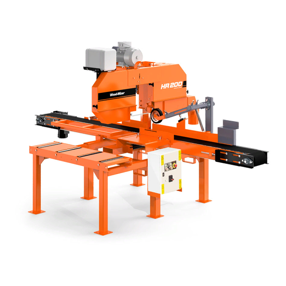
- Page 3 Single Head Resaw HR200 Safety, Operation, Maintenance & Parts Manual HR200EH11S-1 rev. A5.05 HR200EH15S-1 rev. A5.05 Safety is our #1 concern! Read and understand all safety information and instructions before operating, setting up or maintaining this machine. Form #1000...
-
Page 4: Table Of Contents
Table of Contents Section-Page General Contact Information Branches & Authorized Sales CentersWood-Mizer Locations (North and South America) SECTION 1 SAFETY Safety Symbols..................1-1 Safety Instructions ..................1-2 Observe Safety Instructions Wear Safety Clothing Keep Resaw And Area Around Resaw Clean Dispose Of Sawing By-Products Properly Check Resaw Before Operation Keep Persons Away Keep Hands Away... - Page 5 Blade Wheel Assembly, Drive Side ............6-5 Idle Side Blade Wheel Assembly ............6-7 Blade Tensioner Assembly ..............6-9 Middle Throat Screw................6-10 Water Lube Assembly ..............6-11 6.10 HR200 Saw Head Safety Decals ............6-13 6.11 Electric Box & Decals ................6-15 6.12 Blade Housing Cover ................6-16 6.13 Control Panel ..................6-18 6.14...
- Page 6 Table of Contents Section-Page 6.21 Infeed, Outfeed & Return Tables ............6-27 SECTION 7 DC ELECTROMAGNETIC BRAKE (CE ONLY), SIEMENS MOTORS 7-1 Design and Principle of Operation ............7-1 Service ....................7-2 SW-07doc070317 Table of Contents...
- Page 7 Table of Contents Section-Page Table of Contents SW-07doc0703175...
-
Page 8: General Contact Information
Getting Service Wood-Mizer is committed to providing you with the latest technology, best quality and strongest customer service available on the market today. We continually evaluate our customers’ needs to ensure we’re meeting current wood-processing demands. Your comments and suggestions are welcome. -
Page 9: Branches & Authorized Sales Centerswood-Mizer Locations (North And South America)
Branches & Authorized Sales CentersWood-Mizer Locations (North and South America) EUROPE UNITED STATES European Headquarters World Headquarters Wood-Mizer Industries Sp. z o.o. Wood-Mizer LLC Nagórna 114, 62-600 Koło, Poland 8180 West 10th Street Tel.: +48-63-26-26-000 Indianapolis,Indiana 46214-2400, Fax: +48-63-27-22-327 www.woodmizer.eu Tel.: +1-317-271-1542... - Page 10 CROATIA Krešimir Pregernik ITALY Pasquale Felice SERBIA Dragan Markov Pregimex d.o.o. Wood-Mizer Italia Srl Wood-Mizer Balkan d.o.o. S. Batušiæa 31, 10090 Zagreb Cda. Capoiaccio SN Svetosavska GA 3/3; P. Fah 25 Tel.:/Fax: +3851-38-94-668 86012 Cercemaggiore 23 300 Kikinda Krešimir Pregernik Campobasso Tel.:/Fax: +381-230-25-754...
- Page 11 Brazil Headquarters Europe Headquarters Serving Brazil Serving Europe, Africa, West Asia Wood-Mizer do Brasil Wood-Mizer Industries Sp z o.o. Rua Dom Pedro 1, No: 205 Bairro: Sao Jose Nagorna 114 Ivoti/RS CEP:93.900-000 62-600 Kolo, Poland Tel: +55 51 9894-6461/ +55 21 8030-3338/ +55 51 Phone: +48.63.26.26.000...
-
Page 12: Safety
Safety Safety Symbols SECTION 1 SAFETY Safety Symbols The following symbols and signal words call your attention to instructions concerning your personal safety. Be sure to observe and follow these instructions. DANGER! indicates an imminently hazardous situation which, if not avoided, will result in death or serious injury. WARNING! suggests a potentially hazardous situation which, if not avoided, could result in death or serious injury. -
Page 13: Safety Instructions
Wood-Mizer resaw. All Wood-Mizer resaw owners are encouraged to become thoroughly familiar with these applicable laws and comply with them fully while using the machine. -
Page 14: Wear Safety Clothing
Safety Wear Safety Clothing WARNING! Secure all loose clothing and jewelry before operating the resaw. Failure to do so may result in serious injury or death. WARNING! Always wear gloves and eye protection when handling bandsaw blades. Changing blades is safest when done by one person! Keep all other persons away from area when coiling, carrying or changing a blade. -
Page 15: Dispose Of Sawing By-Products Properly
Safety Dispose Of Sawing By-Products Properly Dispose Of Sawing By-Products Properly IMPORTANT! Always properly dispose of all sawing by-products, including sawdust and other debris. Check Resaw Before Operation DANGER! Make sure all guards and covers are in place and secured before operating the resaw. Failure to do so may result in serious injury. -
Page 16: Keep Hands Away
Safety Keep Hands Away Keep Hands Away DANGER! Always shut off the blade motor before changing the blade. Failure to do so will result in serious injury. DANGER! Motor components can become very hot during operation. Avoid contact with any part of a hot motor. Contact with hot motor components can cause serious burns. -
Page 17: Use Proper Maintenance Procedures
Safety Use Proper Maintenance Procedures Use Proper Maintenance Procedures DANGER! Make sure all electrical installation, service and/or maintenance work is performed by a qualified electrician and is in accordance with applicable electrical codes. DANGER! Hazardous voltage inside the electric boxes and at the motor can cause shock, burns, or death. -
Page 18: Keep Safety Labels In Good Condition
Safety Keep Safety Labels In Good Condition carrier equipment for transporting the blades. CAUTION! Always wear gloves when handling the blade. Never grab the blade with bare hands! CAUTION! If the blade breaks during resaw operation, push the EMERGENCY STOP button to stop the blade motor and wait 10 seconds before you open the blade housing cover. - Page 19 Safety Keep Safety Labels In Good Condition See Table 1-1. Pictogram decals used to warn and inform the user about danger in the resaw. TABLE 1-1 Decal View W-M No. Description 096317 CAUTION! Read thoroughly the manual before operating the machine. Observe all safety instructions and rules when operating the resaw.
- Page 20 Safety Keep Safety Labels In Good Condition TABLE 1-1 099221 CAUTION! Keep all persons a safe distance away from work area when operating the machine. 099221 099222 CAUTION! Sawdust outlet. Protect eyes! 096321 Blade movement direction S12004G CAUTION! Always wear safety goggles when operating the resaw! HRdoc070317 Safety...
- Page 21 Safety Keep Safety Labels In Good Condition TABLE 1-1 S12005G CAUTION! Always wear protective ear muffs when operating the resaw! 501465 CAUTION! Always wear safety boots when operating the resaw. 512107 CAUTION! Always wear safety gloves when operating the resaw. 501467 Lubrication Point P11789...
- Page 22 Safety Keep Safety Labels In Good Condition TABLE 1-1 P85070 CE sign 099401 Russian safety certification sign 099401 S20097 Motor rotation direction S20097 509025 Blade drive wheel diameter-blade linear speed 509025 257mm 18 m/s 231mm 20 m/s 197mm 24 m/s 505346 TVS Tensioner Valve Handle Positions TVS 505346...
- Page 23 Safety Keep Safety Labels In Good Condition TABLE 1-1 101176 CAUTION! Compressed air in the system even after electric power disconnection 101176 513181 Pressure value of the pneumatic system 6 bar 0.6 MPa 513181 Safety HRdoc070317 1-12...
-
Page 24: Operation
Operation Control Overview SECTION 2 OPERATION Control Overview 1. Control Panel See Figure 2-1. The control panel includes switches to start and stop the feed track and the saw head. “0” EMERGENCY STOP START STOP STOP FIG. 2-1 CONTROL PANEL COMPONENTS 2. - Page 25 Operation Control Overview 5. Key Switch The key switch has three positions: “0” position - all electrical circuits are off, position - all electrical circuits are on, position - releases the motor disk brake, the blade and the track feed motors ...
-
Page 26: Resaw Setup
Operation Resaw Setup Resaw Setup IMPORTANT! Before starting to use the resaw you have to meet the following conditions: Set up the resaw on firm and level ground. The resaw can be operated with the sawdust collection system only. ... - Page 27 Operation Resaw Setup IMPORTANT! When starting the machine for the first time, check that main motor rotation direction is as indicated by the arrow located on the motor body (fan guard). If the rotation direction is incorrect, invert the phases in the phase inverter located in the power socket (electric box).
-
Page 28: Replacing The Blade
Operation Replacing The Blade Replacing The Blade DANGER! Always shut off the resaw motor before changing the blade. Failure to do so may result in serious injury. WARNING! Always wear gloves and eye protection whenever handling bandsaw blades. Changing blades is safest when done by one person! Keep all other persons away from work area when changing blades. -
Page 29: Tensioning The Blade
Operation Tensioning The Blade Close the blade housing cover. Next, tension the blade as described in the following instructions. Tensioning The Blade See Figure 2-3. Turn the blade tension handle clockwise until the tension gauge indi- cates the recommended tension. Check the blade tension occasionally when adjusting the cant control or while cutting and adjust if necessary. -
Page 30: Tracking The Blade
Operation Tracking The Blade See Table 2-1. The recommended tension for different blades is shown below. Blade Type Blade Dimensions Tension Range Width (mm) Height (mm) 1.07 1015-1088 70-75 1.14 1088-1160 75-80 2735 1.07 1160-1233 80-85 TABLE 2-1 Tracking The Blade 1. -
Page 31: Machine Start
Operation Machine Start 5. Use the cant adjustment bolt, shown in Figure 2-3, to adjust where the blade travels on the blade wheels. To move the blade out on the blade wheel, turn the cant adjustment bolt clockwise. To move the blade in on the blade wheel, turn the bolt counterclockwise. 6. - Page 32 Operation Machine Start “0” EMERGENCY STOP START STOP STOP FIG. 2-5 To stop the blade motor, push the Blade/Track Stop button shown in the figure above. The blade motor also may be stopped by pushing either of the emergency stop buttons. If either of the emergency stops has been used to stop the blade motor, rotate the switch clockwise before restarting the saw head.
- Page 33 Operation Machine Start NOTE: The feed track cannot be started if the blade motor is not started. See Figure 2-7. The speed at which the feed track moves is adjustable. The feed track speed switch, located on the control panel, allows the operator to adjust the feed rate from 0 to ca.
-
Page 34: Blade Height Setting
Operation Blade Height Setting Blade Height Setting 1. Install a blade if needed and check for correct blade tension (see Section 2.4). 2. Set the saw head at the desired height. (The blade height scale shows the height of the blade above the feed track.) See Figure 2-8. -
Page 35: Guide Fence Adjustment
Operation Guide Fence Adjustment Guide Fence Adjustment See Figure 2-9. Loosen the wing nuts. Move the guide fence to the desired cant width. FIG. 2-9 Operation MHdoc070317 2-12... -
Page 36: Water Lube Operation
Operation Water Lube Operation Water Lube Operation See Figure 2-10. The Water Lube System keeps the blade clean. Water flows from a 5-gallon (18.9 liter) bottle through a hose to the blade guide where the blade enters the log. A valve in the bottle cap controls the amount of water flow. Turn valve counterclockwise to open;... -
Page 37: Operation Procedure
Operation Operation Procedure 2.10 Operation Procedure 1. Install a blade if necessary. WARNING! Always wear gloves and eye protection when handling bandsaw blades. Changing blades is safest when done by one person! Keep all other persons away from area when coiling, carrying or changing a blade. Failure to do so may result in serious injury. - Page 38 Operation Operation Procedure 11. Place the test material on the feed track and start the feed track. DANGER! Always be aware of and take proper protective measures against rotating shafts, pulleys, fans, etc. Always stay a safe distance from rotating members and make sure that loose clothing or long hair does not engage rotating members resulting in possible injury.
-
Page 39: Maintenance
MAINTENANCE Wear Life SECTION 3 MAINTENANCE This section lists the maintenance procedures that need to be performed. This symbol identifies the interval (hours of operation) at which each maintenance procedure should be performed. Be sure to refer to the motor manual for maintenance procedures concerning the blade motor. -
Page 40: Blade Guides
MAINTENANCE Blade Guides Blade Guides 1. Check the rollers for performance and wear every blade change. Make sure the rollers are clean and spinning freely. If not, rebuild them. Replace any rollers which have worn smooth or have become cone shaped. See the Parts manual for blade guide rebuild kits and complete roller assemblies. -
Page 41: Blade Tensioner
MAINTENANCE Blade Tensioner Blade Tensioner 1. Grease the screw on the blade tensioner shaft with a lithium grease every fifty hours of operation, but at least once a week. See Figure 3-1. Grease the blade tensioner thread RS_069 FIG. 3-1 Belts 1. -
Page 42: Drive Belt Adjustment
MAINTENANCE Drive Belt Adjustment Drive Belt Adjustment WARNING! Do not for any reason adjust the drive belt with the motor running. Doing so may result in serious injury. See Table 3-2. Check the drive belt tension after the first 20 hours, and every 50 hours thereafter. - Page 43 MAINTENANCE Drive Belt Adjustment turn appropriately the left one.) NOTE: Be sure to adjust the bolts evenly so the motor remains in alignment. 4. Tighten the four motor mounting bolts. Left Adjutment Bolt Right Adjutment Bolt Motor Mounting Bolts (4) rs_013 FIG.
- Page 44 MAINTENANCE Drive Belt Adjustment After performing the alignment, make sure the drive belt tension has not been changed. rs_023 FIG. 3-2 25doc070317 MAINTENANCE...
-
Page 45: Alignment
SECTION 4 ALIGNMENT Alignment Procedures The Wood-Mizer resaw is factory aligned. This section includes instructions on how to realign the resaw completely. Be scrupulous when performing all alignment steps as resaw alignment determines the accuracy of your cuts. The alignment procedure should be performed approximately every 1500 hours of operation. -
Page 46: Blade Installation And Tracking
Blade Installation And Tracking Blade Installation And Tracking See Figure 4-1. Install a blade and apply the proper tension as shown below. Section 2.4 RS_068 095450 Outside face of washer even with indicator Blade Tension Indicator Cant Control Bolt Blade Tensioner Handle FIG. - Page 47 Blade Installation And Tracking [0.04"]). Do not let the teeth ride on the belt. SM0044D 3.0 mm (0.12”) ± 1 mm (0.04”) 4.5 mm (0.18”) 1 1/4" ± 1 mm (0.04”) Blade 1 1/2" Blade FIG. 4-2 To adjust where the blade travels on the idle-side blade wheel, use the cant control shown in Figure 4-7.
-
Page 48: Blade Wheel Alignment
Blade Wheel Alignment Blade Wheel Alignment The blade wheels should be adjusted so they are level in the vertical and horizontal planes. If the blade wheels are tilted up or down, the blade will want to travel in the tilted direction. - Page 49 Blade Wheel Alignment See Figure 4-4. Use the vertical adjustment screws (marked with the blue and yellow arrows in the figure below) to adjust the drive-side blade wheel. Before adjusting the wheel, loosen the drive belt using the adjustment bolts marked with the orange arrows in the figure.
- Page 50 Blade Wheel Alignment 4. Recheck the vertical tilt of the drive-side blade wheel with the blade guide alignment tool. Readjust the blade wheel as necessary until the front and rear of the tool are the same distance from the feed track (± 1.0 mm). 5.
- Page 51 Blade Wheel Alignment 8. Check the position of the blade on the idle-side blade wheel. See Figure 4-6. The horizontal tilt of the blade wheel should be adjusted so that the gullet of an 1-1/4" blade is 3.0 mm out from the front edge of the wheel (± 1.0 mm). 150060 3.0 mm (1/8”) ±...
- Page 52 Blade Wheel Alignment RS_030 Cant Adjustment Bolt FIG. 4-7 9. Check the position of the blade on the drive-side blade wheel. The blade should be positioned on the wheel as described for the idle-side blade wheel. Adjust the drive-side blade wheel if necessary. See Figure 4-8.
- Page 53 Blade Wheel Alignment rs_022 FIG. 4-8 MHdoc070317...
-
Page 54: Saw Head Adjustment
Saw Head Adjustment Saw Head Adjustment See Figure 4-9. The saw head should be set perpendicular to the vertical mast. Using the two sets of adjustment screws in the mast slide pads, you can adjust the saw head in relation to the mast. To raise or lower the outside of the saw head, loosen the locking nuts on either of the sets of screws. -
Page 55: Blade Guide Arm Vertical Adjustment
Blade Guide Arm Vertical Adjustment Blade Guide Arm Vertical Adjustment 1. Adjust the blade guide arm out to within 1/2" (15 mm) of full open. 2. Measure the distance from the top surface of the feed track to the arm. See Figure 4-10. -
Page 56: Blade Guide Arm Horizontal Adjustment
Blade Guide Arm Horizontal Adjustment Repeat adjustments until the arm is the same distance from the track feed in the open and closed position. 6. The blade guide arm should be snug, but not too tight, in the rollers. You should be able to move it in and out with firm hand pressure. - Page 57 Blade Guide Arm Horizontal Adjustment See Figure 4-12. Adjustment Nuts Adjustment Nuts SM0066 FIG. 4-12 4. Adjusting the outside two rollers inward will cause the flange to move away from the blade. 5. Adjusting the two outside rollers outward will cause the flange to move toward the blade. 6.
-
Page 58: Aligning The Blade Guides
Aligning the Blade Guides Aligning the Blade Guides Each Wood-Mizer resaw has two blade guide assemblies that help the blade maintain a straight cut. The two blade guide assemblies are positioned on the cutting head to guide the blade on each side of the material being cut. -
Page 59: Blade Deflection
Blade Deflection Blade Deflection Perform the following steps to achieve proper blade deflection with the blade guides. 1. Raise the carriage until the blade is 200 mm above the feed track. Measure the actual distance with a tape from the top of the track to the bottom of the blade. 2. -
Page 60: Blade Guide Vertical Tilt Adjustment
Blade Guide Vertical Tilt Adjustment Blade Guide Vertical Tilt Adjustment Check that the blade guide does not tilt the blade up or down. A Blade Guide Alignment Tool (BGAT) is provided to help you measure the vertical tilt of the blade. 1. - Page 61 Blade Guide Vertical Tilt Adjustment recheck the tilt of the blade. Loosen jam nuts and turn screws to tilt roller up or down SM0070 FIG. 4-15 5. Measure the distance from the bottom of the tool to the top of the feed track chain at the rear end of the tool.
-
Page 62: Blade Guide Spacing
Blade Guide Spacing 4.10 Blade Guide Spacing HINT: When adjusting blade guide spacing, loosen the top set screw and one side set screw only. This will ensure horizontal and vertical tilt adjustments are maintained when the set screws are retightened. 1. -
Page 63: Blade Guide Horizontal Tilt Adjustment
6. Use the side set screws to adjust the horizontal tilt of the roller. 7. Repeat steps 3-7 for the inner blade guide roller. NOTE: Once the blade guides have been adjusted, any cutting variances are most likely caused by the blade. See the Wood-Mizer® Blade Handbook, Form #600. MHdoc070317 4-19... -
Page 64: Blade Height Scale Adjustment
Blade Height Scale Adjustment 4.12 Blade Height Scale Adjustment After the entire resaw has been aligned and all adjustments made, check that the blade height scale indicates the true distance from the blade to the feed track chain. 1. Measure from the bottom edge on a down-set tooth of the blade to the top of the feed track chain. -
Page 65: Specifications
Specifications Overall Dimensions SECTION 5 SPECIFICATIONS Overall Dimensions See Figure 5-1. The major dimensions of the resaw are shown below (all dimensions are in millimeters). FIG. 5-1 See Table 5-1. The overall dimensions of the resaw are listed in the table below. Weight 875 kg Height... - Page 66 Specifications Overall Dimensions See Figure 5-2. The figure shows the locations of resaw legs. FIG. 5-2 MHdoc070317 Specifications...
-
Page 67: Cutting Capacity
5 HP - 15 HP .042 x 7/8 x 1 1/4“ .042 x 7/8 x 1 1/4 “ .045 x 7/8 x 1 1/4“ F1 HR200 saw is working with a blade with a length of 4.01 m Specifications MHdoc070317... -
Page 68: Blade Motor Specifications
Pssg 132M-4A 11kW 400 V/50Hz; 23 Amp; 1450 r.p.m. TABLE 5-4 See Table 5-5. The noise levels of the Wood-Mizer resaw are listed below Noise level Resaw Equipped With Electric Motor = 96,4 dB (A) TABLE 5-5 1. The noise level measurement was taken in accordance with PN-EN ISO 3746 Standard . -
Page 69: V-Belt Sizes
Specifications V-Belt Sizes V-Belt Sizes See Table 5-6. Belt sizes for the resaw are shown. Belt Description Belt Size Wood-Mizer Part No. Drive Belt (E11) 095079 Drive Belt (E15) 2BX70 P04857-2 Blade Wheel Belt B72.5 017922 TABLE 5-6 Dust Extractor Specifications See Table 5-7. -
Page 70: Replacement Parts
+48-63-2626000 or +48-3912-1319. From the continental U.S., call our toll-free Parts hotline 1-800-448-7881. Have your customer number, vehicle identification number, and part numbers ready when you call. From other international locations, contact the Wood-Mizer distributor in your area for parts. SHRdoc070317 Replacement Parts... -
Page 71: Blade Guide Assembly, Idle Side
Replacement Parts Blade Guide Assembly, Idle Side Blade Guide Assembly, Idle Side rs_033 REF. DESCRIPTION ( Indicates Parts Available In Assemblies Only) PART # BLADE GUIDE ASSEMBLY, HR IDLE SIDE 500500 BLADE GUIDE ROLLER, HR STANDARD COMPLETE 500499 NUT, M12-8 HEX NYLON ZINC LOCK F81034-2 ROLLER, BLADE GUIDE NARROW 500098... -
Page 72: Blade Guide Assembly, Drive Side
Replacement Parts Blade Guide Assembly, Drive Side Blade Guide Assembly, Drive Side HR0001_E REF. DESCRIPTION ( Indicates Parts Available In Assemblies Only) PART # BLADE GUIDE ASSEMBLY, HR DRIVE SIDE 500501 BLADE GUIDE ROLLER, HR STANDARD COMPLETE 500499 NUT, M12-8 HEX NYLON ZINC LOCK F81034-2 ROLLER, BLADE GUIDE NARROW 500098... -
Page 73: Blade Guide Arm Assembly
Replacement Parts Blade Guide Arm Assembly Blade Guide Arm Assembly REF. DESCRIPTION ( Indicates Parts Available In Assemblies Only) PART # ARM, RESAW BLADE GUIDE 093243-1 ROLLER ASSEMBLY, V-GROOVE A09059 Roller, V-Groove S07989 Bearing, 6203-2 NSL 5/8 P06030-1 Ring, Retaining F04254-8 WASHER, 5/8"... -
Page 74: Blade Wheel Assembly, Drive Side
Replacement Parts Blade Wheel Assembly, Drive Side Blade Wheel Assembly, Drive Side RS_035D REF. DESCRIPTION ( Indicates Parts Available In Assemblies Only) PART # WHEEL, RESAW BLADE DRIVE SIDE 500100-1 V-BELT, B72.5 017922-1 BUSHING, 45 SPLIT TAPER 500099 BOLT, M10X35 8.8 HEX HEAD FULL THREAD F81003-17 WASHER, 10.2 SPLIT LOCK ZINC F81055-2... - Page 75 Replacement Parts Blade Wheel Assembly, Drive Side Nut, M12-8 Hex Nylon Zinc Lock F81034-2 Screw, M8x25 A2-70 DIN 913 Set Stainless Steel F81014-3 Nut, M8-8-B Hex Nylon Zinc Lock F81032-2 Ring, W90 Inside Retaining F81090-29 Washer, 8.4 Flat Zinc F81054-1 PULLEY, SPB 224X2/38 (F02312+T31124) 500177 PULLEY, SPB 190X2/38 (F02347+T31124)
-
Page 76: Idle Side Blade Wheel Assembly
Replacement Parts Idle Side Blade Wheel Assembly Idle Side Blade Wheel Assembly RS_36B REF. DESCRIPTION ( Indicates Parts Available In Assemblies Only) PART # WHEEL ASSEMBLY, IDLE SIDE BLADE 088764 Wheel, Idle Side Blade 088419-1 Ring, W100 Inside Retaining F81090-10 Bearing, 3309B.2RSR.TVH FAG 086428 V-BELT, B72.5... - Page 77 Replacement Parts Idle Side Blade Wheel Assembly WASHER, FLANGED ZINC-PLATED 086769-1 NUT, M12X1.25 8.8 HEX THIN ZINC F81034-5 WASHER, Z12.2 SPLIT LOCK ZINC F81056-2 BOLT, M12X1.25X40-8.8 HEX HEAD FULL THREAD ZINC F81004-42 WASHER, 13 FLAT ZINC F81056-1 BOLT, M5X12-5.8-FE/ZN5, PN-M/82105 F81000-5 WASHER, M5 SPLIT LOCK F81052-2...
-
Page 78: Blade Tensioner Assembly
Replacement Parts Blade Tensioner Assembly Blade Tensioner Assembly 20_166b REF. DESCRIPTION ( Indicates Parts Available In Assemblies Only) PART # COMPLETE BLADE TENSIONER 510640 HOUSING, BALL THRUST BEARING 510635 SOCKET, BEARING HOUSING 510634-1 BEARING, 51103. BALL THRUST 086675 WASHER 510633-1 SPRING, n3mm 088992 BUSHING, BLADE TENSIONER SCREW... -
Page 79: Middle Throat Screw
Replacement Parts Middle Throat Screw WASHER, 8.2 SPLIT LOCK ZINC F81054-4 PIN, 5x30 ROLL ZINC F81044-21 BLOCK, TENSIONER HANDLE MOUNT 096730 BUSHING, GFM-1618-17 089589 WASHER, 6.4 FLAT ZINC F81053-1 DECAL, PRESSURE VALUES 510643 BOLT, M6x16-8.8 HEX HEAD FULL THREAD ZINC F81001-15 BOLT, M8x70-8.8 HEX HEAD ZINC F81002-71... -
Page 80: Water Lube Assembly
Replacement Parts Water Lube Assembly Water Lube Assembly REF. DESCRIPTION ( Indicates Parts Available In Assemblies Only) PART # BOTTLE KIT, LT20 WATER LUBE 091036 TRAY WELDMENT, LT20 WATER LUBE 091033-1 STRAP, 20 RUBBER W/HOOK P11668 SCREW M6X25-8.8-FE/ZN5 PN/M-82406 F81001-20 WASHER, FLAT ZINC F81053-11 NUT, M6-8-B HEX NYLON ZINC LOCK... - Page 81 Replacement Parts Water Lube Assembly REF. DESCRIPTION ( Indicates Parts Available In Assemblies Only) PART # FITTING, 3/4FPTX3/4MPT 014636 VALVE, 3/4 NPT ELBOW 3/4 MALE OUTLET PVC 014100 FILTER, WATER LUBE 016086 REDUCER, 5/8NPT/3/8BARB WATER LUBE 014113 TUBING, WATER LUBE R01885 Replacement Parts SHRdoc070317...
-
Page 82: Hr200 Saw Head Safety Decals
Replacement Parts HR200 Saw Head Safety Decals 6.10 HR200 Saw Head Safety Decals 099220 099221 099222 510643 1015-1088 70-75 1088-1160 75-80 1160-1233 80-85 Rs_063_B 094540_Manual REF. DESCRIPTION ( Indicates Parts Available In Assemblies Only) PART # DECAL-PICTOGRAM KIT, RESAW - COMPLETE... - Page 83 Replacement Parts HR200 Saw Head Safety Decals DECAL, READ OPERATOR’S MANUAL (PICTOGRAM) 096317 DECAL, BLADE ALIGNMENT P11789 DECAL, EYE PROTECTION WARNING (PICTOGRAM) S12004G DECAL, EAR PROTECTION WARNING (PICTOGRAM) S12005G DECAL, KEEP AWAY DANGER, PICTOGRAM 099221 DECAL, BLADE TENSION INDICATOR ADJUSTMENT...
-
Page 84: Electric Box & Decals
Replacement Parts Electric Box & Decals 6.11 Electric Box & Decals TBCE03B REF. DESCRIPTION ( Indicates Parts Available In Assemblies Only) PART # DECAL, HIGH VOLTAGE INSIDE THE ELECTRIC BOX (PICTOGRAM) 096316 DECAL, REMOVE THE PLUG BEFORE OPENING THE BOX (PICTOGRAM) 096319 ELECTRIC BOX W/SPEED CONTROLLER 087926... -
Page 85: Blade Housing Cover
Replacement Parts Blade Housing Cover 6.12 Blade Housing Cover rs_071_A 099666_Manual REF. DESCRIPTION ( Indicates Parts Available In Assemblies Only) PART # COVER WELDMENT, RESAW BLADE HOUSING 093251-1 LATCH, FLEXIBLE DRAW 014829 BOLT, M5 X 16-5.8 HEX HEAD FULL THREAD ZINC F81000-51 NUT, M5-8 DIN 985 ZINC F81030-2... - Page 86 Replacement Parts Blade Housing Cover NUT, M4-B HEX NYLON ZINC LOCK F81029-1 GUARD, BLADE GUIDE ROLLER PAINTED 516925-1 BOLT, M6X16 8.8 HEX HEAD FULL THREAD ZINC F81001-15 CHUTE, RESAW SAWDUST 094059-1 PLUG, SR1086-9.5 096846 BOLT M8X16 -8.8-B HEX HEAD FULL THREAD ZINC F81002-20 WASHER 8,2 FE/ZN9 F81054-4...
-
Page 87: Control Panel
Replacement Parts Control Panel 6.13 Control Panel RS_065 REF. DESCRIPTION ( Indicates Parts Available In Assemblies Only) PART # RESAW & HR CONTROL BOX 093458 Box, M22-I6 (216540) Control 093750 Potentiometer, M22-R1K (229489) 093749 Connector, DP 16/H F81096-7 Switch, M22 3-Position 091360 Operator, M22-WRS3 Key Switch 095001... -
Page 88: Up/Down System Screws
Replacement Parts Up/Down System Screws 6.14 Up/Down System Screws REF. DESCRIPTION ( Indicates Parts Available In Assemblies Only) PART # SCREW, M8X20-8.8 HEX SOCKET HEAD CAP ZINC F81002-30 UP/DOWN SYSTEM, HR500-1/SHR MANUAL COMPLETE Patrz rozdział 6.15 517306 6.15 Manual Up/Down System REF. -
Page 89: Vertical Mast Slide Pads
Replacement Parts Vertical Mast Slide Pads 6.16 Vertical Mast Slide Pads REF. DESCRIPTION ( Indicates Parts Available In Assemblies Only) PART # ANGLE, VERTICAL MAST TUBE 093890 BOLT, M10X125-8.8 HEX HEAD ZINC F81003-18 WASHER, 10.5 FLAT ZINC F81055-1 Replacement Parts SHRdoc070317 6-20... - Page 90 Replacement Parts Vertical Mast Slide Pads NUT, M10-8-B HEX NYLON ZINC LOCK F81033-1 PADS, DELRIN UP/DOWN SLIDE M04096 PLATE, SLIDE PAD MOUNTING PAINTED 093246-1 NUT, SLIDE PAD ADJUSTMENT ZINC-PLATED 086683 BOLT, M8X35-8.8 HEX HEAD FULL THREAD ZINC F81002-13 NUT, M8-8-B HEX NYLON ZINC LOCK F81032-2 BOLT, M8X25-8.8-B HEX HEAD FULL THREAD ZINC F81002-5...
-
Page 91: Motor Assembly
Replacement Parts Motor Assembly 6.17 Motor Assembly REF. DESCRIPTION ( Indicates Parts Available In Assemblies Only) PART # MOTOR, 7.5kW Sg132M-4B - HM 094996 MOTOR, 11kW Sg132M-4PC-HM 093219 PULLEY, SPB 100X2/38 (F02312+T31079) 500176 PULLEY, SPB 125X2/38 (F02320+F31109) 500570 SCREW, M8X8-33H HEX SOCKET SET FLAT POINT ZINC F81014-1 BOLT, M10X45-8.8 HEX HEAD FULL THREAD ZINC F81003-3... -
Page 92: Feed Track Assembly (Hr200)
Feed Track Assembly (HR200) 6.18 Feed Track Assembly (HR200) RS_057C REF. DESCRIPTION ( Indicates Parts Available In Assemblies Only) PART # MOTOR & GEAR BOX, MR-63/24.5/0.75-1400/F3/B6 508486 PULLEY, HR200 WITH GLUE AND COVERING 513943 PULLEY, HR200 SIDE PAINTED 097949-1 6-23 SHRdoc070317 Replacement Parts... - Page 93 BOLT, M16X50-8.8 HEX HEAD FULL THREAD ZINC F81006-7 WASHER, 17 FLAT ZINC F81058-1 NUT, M16-8 HEX NYLON ZINC LOCK F81036-2 BRACKET, HR200 GEAR BOX MOUNT PAINTED 094898-1 BRACKET, HR200 PULLEY MOUNT PAINTED 094889-1 BOLT, M10X35-8.8 HEX HEAD FULL THREAD ZINC F81003-17 WASHER, 10.5 SPECIAL FLAT ZINC...
-
Page 94: Hold-Down Roller Assembly, Hr200
( Indicates Parts Available In Assemblies Only) PART # ARM, HR200 HOLD-DOWN ROLLER PIVOT 094965-1 ARM, HR200 HOLD-DOWN ROLLER OUTSIDE 094960-1 ARM WELDMENT, HR200 HOLD-DOWN ROLLER INSIDE PAINTED 094913-1 WHEEL, FI 200 MG 61N (HR200) W/BUSHING 094465 BEARING, UCFL 206 CX BALL 090851 BOLT, M16X100-8.8 HEX HEAD FULL THREAD ZINC... -
Page 95: Guide Fence Assembly, Hr200
6.20 Guide Fence Assembly, HR200 RS_059 REF. DESCRIPTION ( Indicates Parts Available In Assemblies Only) PART # FENCE WELDMENT, HR200 LOG GUIDE PAINTED 094901-1 WASHER, 17 FLAT ZINC F81058-1 NUT, M16 WING ZINC F81036-3 SCREW, M10X25 8.8 HEX SOCKET HEAD CAP ZINC F81003-32 WASHER, 10.5 FLAT ZINC... - Page 96 Roller, 76 Dia. x 400 w/Internal Thread Table Painted 093787-1 Bolt, M10x35-8.8 Hex Head Full Thread Zinc F81003-17 Washer, 10.5 Flat Zinc F81055-1 TABLE ASSEMBLY, RESAW FEED (HR200-T) 093790 Table Weldment, Feed Painted 094831-1 Roller, 76 Dia. x 400 w/Internal Thread Table Painted 093787 Bolt, M10x35-8.8 Hex Head Full Thread Zinc...
- Page 97 Replacement Parts Infeed, Outfeed & Return Tables BRACKET, RESAW CONTROL BOX MOUNT PAINTED 094075-1 BOLT, M8X55 8.8 HEX HEAD ZINC F81002-8 WASHER, 8.4 FLAT ZINC F81054-1 TUBE, RESAW CONTROL BOX SPACER PAINTED 094738-1 Replacement Parts SHRdoc070317 6-28...
- Page 98 DC Electromagnetic Brake (CE Only), Siemens motors Design and Principle of Operation SECTION 7 DC ELECTROMAGNETIC BRAKE (CE ONLY), SIEMENS MOTORS 1 - Electromagnet, 2 - Armature complete with brake linings, 3 - Fan, 4 - Retaining bolt 5 - Central spring, 6 - Special washer, 7 - Set screw, 8 - Self-locking nut,...
- Page 99 DC Electromagnetic Brake (CE Only), Siemens motors Service presses the armature with brake linings (2) against the fan and the brake is thus applied. Service During normal operation and at the routine inspections verify the air gap and check if all screws are tight.
- Page 100 DC Electromagnetic Brake (CE Only), Siemens motors Service EAdoc070317 DC Electromagnetic Brake (CE Only), Siemens...
- Page 101 EC declaration of conformity according to EC Machinery Directive 2006/42/EC We herewith declare, Wood-Mizer Industries sp. z o.o. 114 Nagorna street, 62-600 Kolo; Poland. That the following described machine in our delivered version complies with the appropriate basic safety and health requirements of the EC Machinery Directive 2006/42/EC based on its design and type, as brought into circulation by us.
Need help?
Do you have a question about the HR200 and is the answer not in the manual?
Questions and answers