Table of Contents
Advertisement
Advertisement
Table of Contents
Troubleshooting

Related Manuals for Wood-mizer LT70L DH


Summary of Contents for Wood-mizer LT70L DH
- Page 3 Wood-Mizer ® Safety, Setup, Operation & Maintenance Manual LT70L DH rev. B7.00 LT70L DH WIDE rev. B7.00 Safety is our #1 concern! Read and understand all safety information and instructions before operating, setting up or maintaining this machine. Form #1041 This is the original language for the manual.
-
Page 4: Table Of Contents
Table of Contents Section-Page SECTION 1 SAFETY Safety Symbols..................1-1 Safety Instructions ..................1-2 Belt Sizes ....................1-16 Blade Sizes ...................1-16 SECTION 2 SERVICING THE SAWMILL Customer and Sawmill Identification.............2-1 SECTION 3 SAWMILL SETUP Sawmill Setup..................3-1 Stationary Sawmill Setup ...............3-3 Sawmills with Cable Guide Portable Sawmill Setup ................3-8 Middle Track Cover ................3-11 Replacing The Blade ................3-12... - Page 5 Table of Contents Section-Page Drum Switches ..................5-6 Miscellaneous ..................5-7 Brake Adjustment...................5-8 Drive Belt Adjustment................5-9 5.10 Up/Down System..................5-10 5.11 Charging The Battery (DC Only) ............5-12 5.12 Hydraulic System .................5-13 5.13 Power Feed ...................5-15 SECTION 6 TROUBLESHOOTING GUIDE Sawing Problems ..................6-1 Electrical Problems.................6-3 Power Feed Problems ................6-5 Power Feed Circuit Troubleshooting............6-7 Hydraulic Problems ................6-10...
- Page 6 Table of Contents Section-Page Vertical Adjustment of Side Supports..........7-14 Blade Height Scale Adjustment Complete Alignment Procedure ............7-16 Frame Setup Blade Installation Blade Wheel Alignment Bed Rail Adjustment Blade Guide Installation Blade Guide Arm Alignment Blade Guide Deflection Blade Guide Vertical Tilt Alignment Blade Guide Horizontal Tilt Adjustment Blade Guide Flange Spacing Blade Guide Level...
-
Page 7: Section 1 Safety
Safety Safety Symbols SECTION 1 SAFETY Safety Symbols The following symbols and signal words call your attention to instructions concerning your personal safety. Be sure to observe and follow these instructions. DANGER! indicates an imminently hazardous situation which, if not avoided, will result in death or serious injury. -
Page 8: Safety Instructions
It is always the owner's responsibility to comply with all applicable federal, state and local laws, rules and regulations regarding the ownership, operation and towing of your Wood-Mizer sawmill. All Wood-Mizer mill owners are encouraged to become thoroughly familiar with these applicable laws and comply with them fully while using or towing the mill. - Page 9 Safety Safety Instructions WEAR SAFETY CLOTHING WARNING! Secure all loose clothing and jewelry before operating the sawmill. Failure to do so may result in serious injury or death. WARNING! Always wear gloves and eye protection when handling bandsaw blades. Changing blades is safest when done by one person! Keep all other persons away from area when coiling, carrying or changing a blade.
- Page 10 Safety Safety Instructions WARNING! Use ONLY water with the water lube accessory. Never use flammable fuels or liquids. If these types of liquids are necessary to clean the blade, remove it and clean with a rag. Failure to do so may result in serious injury or death.
- Page 11 Safety Safety Instructions Use extreme care to avoid spilling or splashing electrolyte (which is dilute sulfuric acid) as it can destroy clothing and burn the skin. If electrolyte is spilled or splashed on clothing or the body, it should be neutralized immediately and then rinsed with clean water.
- Page 12 Safety Safety Instructions CHECK SAWMILL BEFORE OPERATION DANGER! Make sure all guards and covers are in place and secured before operating or towing the sawmill. Failure to do so may result in serious injury. Be sure the blade housing and pulley covers are closed (i.e. the safety switches located on them are engaged).
- Page 13 Safety Safety Instructions DANGER! Always keep hands away from moving bandsaw blade. Failure to do so will result in serious injury. DANGER! Always be aware of and take proper protective measures against rotating shafts, pulleys, fans, etc. Always stay a safe distance from rotating members and make sure that loose clothing or long hair does not engage rotating members resulting in possible injury.
- Page 14 Safety Safety Instructions WARNING! Consider all electrical circuits energized and dangerous. WARNING! Never assume or take the word of another person that the power is off; check it out and lock it out. WARNING! Do not wear rings, watches, or other jewelry while working around an open electrical circuit.
- Page 15 Safety Safety Instructions USE CAUTION WHEN WORKING WITH HEAVY LOGS WARNING! Always make sure log is clamped securely before sawing. Failure to do so may result in serious injury or death. AUTOMATIC BOARD RETURN SAFETY DANGER! Keep all persons out of the path of returning boards. Failure to do so will result in serious injury.
- Page 16 Safety Safety Instructions CAUTION! Never clean the blade or the blade wheels with a brush or a scraper during sawmill operation. CAUTION! Before installation of the blade, inspect it for damage and cracks. Use only properly sharpened blades. Always handle the blade with extreme caution.
- Page 17 Safety Safety Instructions See Table 1-1. Pictogram decals used to warn and inform the user about danger in the LT70. TABLE 1-1 Decal View W-M No. Description 096317 CAUTION! Read thoroughly the manual before operating the machine. Observe all safety instructions and rules when operating the sawmill.
- Page 18 Safety Safety Instructions TABLE 1-1 098176 CAUTION! Keep away from debarker blade! 098176 096316 CAUTION! Do not open or close the electric box when the switch is not in the “0” position. 096319 CAUTION! Disconnect power supply before opening the box. 085977B Do not lift the machine grasping by the element!
- Page 19 Safety Safety Instructions TABLE 1-1 086099 CAUTION! Keep away - hot parts! 086099 099222 CAUTION! Sawdust outlet. Protect eyes! 099542 CAUTION! Trailer. 099542 096321 Blade movement direction 505189 Tensioner ball valve lever 505189 Safety 60HDdoc102619 1-13...
- Page 20 Safety Safety Instructions TABLE 1-1 512240 Clean the chain from sawdust every 50 hours of operation or once a week. 512240 512158 Lubricate the chain every 50 hours of operation or once a week. 512158 S12004G CAUTION! Always wear safety goggles when operating the sawmill! S12005G CAUTION! Always wear protective ear...
- Page 21 Safety Safety Instructions TABLE 1-1 501465 CAUTION! Always wear safety boots when operating the sawmill. 501467 Lubrication Point P11789-70 Aligning the blade on the wheels P11789-70 P85070 CE safety certification 099401 Russian safety certification 099401 S20097 Motor rotation direction S20097 Safety 60HDdoc102619 1-15...
-
Page 22: Belt Sizes
Safety Belt Sizes Belt Sizes See Table 1-2. Belt sizes are shown below. Description Belt Size Wood-Mizer Part # Motor Drive Belt ( E25 ) 3B/HB 089464 2462La Engine Drive Belt ( D42 ) 3B/HB 2462La 089464 Alternator Belt ( DC mills only ) -
Page 23: Section 2 Servicing The Sawmill
SECTION 2 SERVICING THE SAWMILL Customer and Sawmill Identification Each Wood-Mizer sawmill has a model number and a 17-digit Vehicle Identification Number (VIN). In addition, when you pick up your mill, you will receive a customer number. These three numbers will help expedite our service to you. - Page 24 Servicing The Sawmill Customer and Sawmill Identification The model number and V.I.N. can be found in the following locations. MODEL NUMBER AND V.I.N. LOCATIONS 60HDdoc102619 Servicing The Sawmill...
-
Page 25: Sawmill Setup
Sawmill Setup Sawmill Setup SECTION 3 SAWMILL SETUP Sawmill Setup IMPORTANT! Before starting to use the sawmill you have to meet the following conditions: Set up the sawmill on firm, level ground and level the sawmill. Secure the sawmill to the ... - Page 26 Sawmill Setup Sawmill Setup or death. sm0376 60HDdoc102619 Sawmill Setup...
-
Page 27: Stationary Sawmill Setup
Sawmill Setup Stationary Sawmill Setup Stationary Sawmill Setup Prepare a firm, level area where the sawmill can be anchored. There should be enough room around the sawmill for operators, sawdust removal, log loading and board removal. A cement pad with 5/8” (16 mm) diameter anchor bolts is recommended. - Page 28 Sawmill Setup Stationary Sawmill Setup See Figure 3-1. Bed Rail Bed Rail Stop Block Stop Block Side Support Side Support Sm0130b FIG. 3-1 60HDdoc102619 Sawmill Setup...
-
Page 29: Sawmills With Cable Guide
Sawmill Setup Sawmills with Cable Guide 3.2.2 Sawmills with Cable Guide See Figure 3-1. The figure below shows setup of the sawmill, the control box and the guiding rail columns. Secure the columns to the ground using 16mm anchored bolts. FIG. - Page 30 Sawmill Setup Sawmills with Cable Guide See Figure 3-2. The electrical wires should be installed on the guiding rail as shown below. FIG. 3-2 See Figure 3-3. Install the rail bracket arm as shown below. M8x30 Bolt FIG. 3-3 60HDdoc102619 Sawmill Setup...
- Page 31 Sawmill Setup Sawmills with Cable Guide See Figure 3-4. Install the guiding rail. FIG. 3-4 See Figure 3-5. Sawmill Setup 60HDdoc102619...
-
Page 32: Portable Sawmill Setup
Sawmill Setup Portable Sawmill Setup FIG. 3-5 Portable Sawmill Setup WARNING! Do not set up the mill on ground with more than a 10 degree incline. If setup on an incline is necessary, put blocks under one side of the mill or dig out areas for outrigger legs to keep mill level. Setting up the mill on an incline could cause it to tip over, resulting in serious personal injury. - Page 33 Sawmill Setup Portable Sawmill Setup WARNING! Always make sure the trailer is supporting the sawmill frame when operating a sawmill with adjustable outriggers. Failure to do so may result in serious injury or death. The adjustable outriggers are intended to support the saw frame with assistance from the trailer. 1.
- Page 34 Sawmill Setup Portable Sawmill Setup CAUTION! If setup sawmill on a boggy terrain (such as deep mud or sand) place the board or metal plate under each outrigger leg to prevent it from sinking. 1. Unhook the carriage safety chain, located at the bottom of the vertical mast. 2.
-
Page 35: Middle Track Cover
Sawmill Setup Middle Track Cover Middle Track Cover Before operating the sawmill do as follows: 1. Clean the upper and lower rails to remove any sawdust and rust preventives. 2. Unbolt and remove the middle track cover from its storage position. 3. -
Page 36: Replacing The Blade
Sawmill Setup Replacing The Blade Replacing The Blade DANGER! Always shut off the sawmill engine before changing the blade. Failure to do so will result in serious injury. WARNING! Always wear gloves and eye protection when handling bandsaw blades. Changing blades is safest when done by one person! Keep all other persons away from area when coiling, carrying or changing a blade. -
Page 37: Tensioning The Blade
Sawmill Setup Tensioning The Blade Tensioning The Blade Before tensioning the blade, check the air pressure gauge to see that the air tension system is properly charged. The gauge should read 50 PSI, i.e. .34 MPa (yellow colour) with the blade tension completely released. - Page 38 Sawmill Setup Tensioning The Blade See Table 3-6. T he recommended tension for different blades is shown below. Blade Type Blade Dimensions Tension range Thickness (mm) Width (mm) 2735 1.07 60-62 0.41-0.43 3735 1.14 0.45 1.07 60-62 0.41-0.43 1.14 62-65 0.43-0.45 1.27 65-70...
-
Page 39: Tracking The Blade
Sawmill Setup Tracking The Blade Tracking The Blade 1. Turn the key switch to #3 position. 2. Engage the blade switch. 3. Manually spin one of the blade wheels until the blade positions itself on the blade wheels. 4. Check that if the blade is properly positioned on the blade wheels. See Figure 3-7. - Page 40 Sawmill Setup Tracking The Blade See Figure 3-7. Turn bolt clockwise to move blade out on DETAIL wheel; counterclock- wise to move blade in on wheel. Cant Adjustment Bolt (See Detail) FIG. 3-7 To move the blade out on the blade wheel, turn the cant adjustment bolt clockwise. To move the blade in on the blade wheel, turn the bolt counterclockwise.
-
Page 41: Starting The Engine (Or Motor)
Sawmill Setup Starting The Engine (or Motor) DANGER! Make sure all guards and covers are in place and secured before operating or towing the sawmill. Failure to do so may result in serious injury. Be sure the blade housing and pulley covers are closed (i.e. -
Page 42: Section 4 Sawmill Operation
Sawmill Operation Hydraulic Control Operation SECTION 4 SAWMILL OPERATION Hydraulic Control Operation The hydraulic control levers become operational when the contacts at the bottom of the saw head touch the power strip on the frame tube. The hydraulic control levers will only work when the saw head is close enough to the front end of the sawmill to touch the power strip. - Page 43 Sawmill Operation Hydraulic Control Operation See Figure 4-2. A/DH5 Hydraulic System Front Rear Clamp Clamp Rear Front Up/Down Clamp Clamp Up/Down A/DH3 Up/Down Up/Down Front Clamp Rear Clamp Front Rear In/Out In/Out HD0185 Clamp Clamp In/Out In/Out FIG. 4-2 See Figure 4-3. A/DH7 Hydraulic System 094970 Clamp Clamp II...
- Page 44 Sawmill Operation Hydraulic Control Operation See Figure 4-4. The portable hydraulic sawmills have seven control levers to load, clamp, turn and level logs. Front Toe Front Toe Middle Toe Middle Toe Board Board Board Board Rear Toe Rear Toe Board Board Turner Turner...
- Page 45 Sawmill Operation Hydraulic Control Operation 1. Move the clamp out and down so it will not get in the way of logs being loaded onto the bed. Lower the clamp in/out lever to move the clamp out toward the loading side of the sawmill. Lower the clamp up/down lever to lower the clamp below the bed level.
-
Page 46: Loading, Turning And Clamping Logs
Sawmill Operation Loading, Turning And Clamping Logs Loading, Turning And Clamping Logs To Load Logs 1. Move the saw carriage to the front end of the frame. CAUTION! Before loading a log, be sure the cutting head is moved far enough forward so the log does not hit it. - Page 47 Sawmill Operation Loading, Turning And Clamping Logs 6. Disengage the clamp. The log can be turned now. Repeat steps 4 through 7 until the log is turned as desired. Turning small cants If you are turning a small cant, use the middle log clamp to turn the cant, instead of the log turner. 1.
-
Page 48: Up/Down Operation
Sawmill Operation Up/Down Operation To Level A Tapered Log Raise the appropriate lever to raise the front, middle or rear toe board until the heart of the log measures the same distance from the bed rails at each end of the log. Up/Down Operation This section describes operation of the up/down system with the standard controls. -
Page 49: Blade Guide Arm Operation
Sawmill Operation Blade Guide Arm Operation Blade Guide Arm Operation 1. Look down the length of the log to see its maximum width. The outer blade guide should be adjusted to clear the widest section of the log by less than 1" (25.4 mm). 2. -
Page 50: Power Feed Operation
Sawmill Operation Power Feed Operation Power Feed Operation See Figure 4-7. The power feed system moves the carriage forward and backward by using two swi- tches on the control panel. Saw Head Carriage Forward Forward Saw Head Carriage Reverse Reverse Forward Feed Rate Forward Feed Rate 3H0280... - Page 51 Sawmill Operation Power Feed Operation Using The Power Feed 1. To move the carriage forward, push the drum switch handle forward and turn the feed rate switch clockwise. HINT: To get a straight cut in the first part of the board, feed the blade into the log at a slow speed. This stops the blade from flexing and dipping up or down.
-
Page 52: Cutting The Log
Cutting The Log Cutting The Log The following steps guide you through normal operation of the Wood-Mizer sawmill. 1. Once the log is placed where you want it and clamped firmly, turn the key switch to the #1 position. 2. Use the blade height scale to determine where to make your first cut (See Section 4.9). -
Page 53: Edging
Edging Edging The following steps guide you through edging boards on the Wood-Mizer sawmill. 1. Raise the side supports to 1/2 the height of the flitches, or the boards that need to be edged. 2. Stack the flitches on edge against the side supports. -
Page 54: Optional Cutting Procedure
Sawmill Operation Optional Cutting Procedure Optional Cutting Procedure In order to achieve maximum production rates, it may be desirable to leave the blade engaged when returning the carriage. (Normal operation procedures recommend disengaging the blade before returning the carriage for maximum blade life and fuel economy.) DANGER! If leaving the blade engaged for maximum production rates, make sure the off-bearer stays out of the path of the blade. - Page 55 Sawmill Operation Blade Height Scale Blade Height Indicator The blade height indicator has two horizontal, red lines on both sides. Readings should be taken with eyes level with the indicator, when the two red lines are in line. This will allow to avoid the parallax error (different scale readings depending on the angle of vision).
-
Page 56: 4.10 Water Lube Operation
15 seconds. This will clean the blade of sap buildup. Wipe the blade dry with a rag before storing or sharpening. For further lubrication benefits, add one 12oz. bottle of Wood-Mizer Lube Additive to 5 gallons of water. Wood-Mizer Lube Additive enables some previously impossible timbers to be cut by significantly reducing resin buildup on the blade. -
Page 57: 4.11 Lt70 Wide Lube System Operation
WARNING! Use ONLY water and Wood-Mizer Lube Additive with the water lube accessory. Never use flammable fuels or liquids such as diesel fuel. If these types of liquids are necessary to clean the blade, remove it and clean with a rag. -
Page 58: 4.12 Preparing The Sawmill For Towing
Blow any remaining oil from the lube hose. 4.12 Preparing The Sawmill For Towing The Wood-Mizer trailer package makes transporting your sawmill easy and convenient. To get your sawmill ready for towing, follow these instructions. - Page 59 Sawmill Operation Preparing The Sawmill For Towing CAUTION! Move the hydraulic clamp and turner to provide maximum ground clearance before towing. Failure to do so may result in damage to the sawmill. 3. Move the carriage forward to the travel position over the rear bed rail. Position the hole in the saw head over the travel rest pin.
- Page 60 Sawmill Operation Preparing The Sawmill For Towing See Figure 4-4. Protection Belt FIG. 4-4 CAUTION! It is important that the lower stop bolts are properly adjusted to secure the carriage on the track rail. Failure to properly adjust the stop bolts can cause saw head damage, especially during mill transportation.
- Page 61 Sawmill Operation Preparing The Sawmill For Towing See Figure 4-5. Loosen jam nut Loosen jam nut and turn bolt to and turn bolt to raise or lower raise or lower stop bolt stop bolt FIG. 4-5 7. Use the hydraulic controls to raise the log turner and loader as high as they will go. Manually lift the loader and hook the loader chains to the sawmill frame.
- Page 62 Sawmill Operation Preparing The Sawmill For Towing cable to fasten blade housing covers. 9. Remove all loose objects from the bed of the mill. 10. Place both fenders in the slots located behind the trailer tires. Raise and secure all but the very front outrigger.
-
Page 63: Section 5 Maintenance
Maintenance Wear Life SECTION 5 MAINTENANCE This section lists the maintenance procedures that need to be performed. See the located after this section for a complete list of maintenance procedures Maintenance Log and intervals. Keep track of machine maintenance by filling in the machine hours and the date you perform each procedure. -
Page 64: Blade Guides
Maintenance Blade Guides Blade Guides 1. Check the rollers for performance and wear every blade change. Make sure the rollers are clean and spinning freely. If not, rebuild them. Replace any rollers which have worn smooth or have become cone shaped. Steel Guide Blocks 2. - Page 65 Preventing sap buildup on the blade is critical when using the high-performance blade guide system. If the wood you are sawing leaves sap buildup using plain water in the blade lube system, use Wood-Mizer lube additive (Part No. 033439). Maintenance...
-
Page 66: Throat Screw
Maintenance Throat Screw Throat Screw Make sure the blade screw in the top center of the C-frame is 1/16" (1.5 mm) away from the blade. If not, loosen the nut and adjust the screw as necessary. Check the screw every blade change. Failing to maintain this adjustment will lead to early blade breakage. - Page 67 Maintenance Carriage Track, Wiper & Scrapers CAUTION! Keep track rails free of rust. Formation of rust on the track rail in the areas where the cam bearings roll can cause rapid deterioration of the track rail's surface. Lubricate the rails by wiping them with Dexron III ATF transmission fluid, 10W30 motor oil, or 3-in-1 turbine oil.
-
Page 68: Vertical Mast Rails
Lubricate the up/down and power feed drum switch contacts inside the control panel every fifty hours of operation. Use only contact grease supplied by Wood-Mizer. Remove the control panel cover. Use a cotton swab to apply grease to the switch contact ends. -
Page 69: Miscellaneous
Maintenance Miscellaneous vomiting - contact a physician. KEEP OUT OF THE REACH OF CHILDREN. Miscellaneous 1. Oil all chains with Dexron III ATF every fifty hours of operation. CAUTION! Do not use chain lube. It causes sawdust buildup in chain links. -
Page 70: Brake Adjustment
Maintenance Brake Adjustment Brake Adjustment 1. The engine RPM should be 1150 when idling and 3000 when running. 2. The throttle cable mounting bolt should be placed in the middle hole of the acceleration lever located on the engine. 3H0748 3. -
Page 71: Drive Belt Adjustment
Maintenance Drive Belt Adjustment 5. Never increase the engine RPM by moving manually the acceleration lever on the engine. Increasing the engine RPM when the brake is engaged will result in quick clutch damage. The throttle cable should move smoothly and easily in the housing. Drive Belt Adjustment DANGER! Never adjust the drive belts and the drive belt bracket while... -
Page 72: 5.10 Up/Down System
Maintenance Up/Down System 5.10 Up/Down System Adjust the up/down chain tension as needed. Measure chain tension with the head all the way to the top of the vertical mast. Find the chain adjusting bolt at the bottom of the mast. Use the adjustment nut to adjust the bolt until the center of the chain can be deflected 3/4”... - Page 73 Maintenance Up/Down System Adjustment Adjustment Bolts Bolts 80_105 Mounting Mounting Bolts Bolts FIG. 5-4 Periodically check the belt for wear. Replace any damaged or worn belts as needed. 2. When oil leaks from the gear reducer please contact Customer Service. 3.
-
Page 74: Charging The Battery (Dc Only)
Maintenance Charging The Battery (DC Only) 5.11 Charging The Battery (DC Only) DANGER! Batteries expel explosive gases. Keep sparks, flames, burning cigarettes, or other ignition sources away at all times. Always wear safety goggles and a face shield when working near batteries. Failure to do so will cause serious injury. -
Page 75: 5.12 Hydraulic System
Maintenance Hydraulic System 1. Raise the saw head to access the battery box. IMPORTANT: Be careful not to overcharge the battery, especially when using a high-rate or “boost” charger (40 amps or higher). These are intended to quickly charge a good battery that is discharged. They are not intended for unattended or long-term charging. - Page 76 Maintenance Hydraulic System TEMPERATURE TEMPERATURE -30° -20° -10° 0° 10° 20° 30° 40° 50° 60° 70° 80° 90° 100° 110° 120° -35° -29° -23° -18° -12° -7° -1° 5° 10° 16° 21° 27° 32° 38° 44° 49° Level A Fluid Level A Fluid Level B Fluid Level B Fluid...
-
Page 77: 5.13 Power Feed
Maintenance Power Feed 5.13 Power Feed 1. Adjust the power feed chain as needed. Measure the power feed chain tension with the saw head all the way toward the front of the mill. Use the adjustment nut on the feed tensioner at the front of the mill to tighten or loosen the power feed chain. - Page 78 MAINTENANCE LOG (Check Engine And Option Manuals For Additional Maintenance Procedures) Check Blade Screw Daily - Every Blade Change See Section 5.2 Check Blade Guide Performance Daily - Every Blade Change See Section 5.2 Remove Excess Sawdust From Blade Wheel Hous- Daily - Every Blade Change See Section 5.3 DAILY MAINTENANCE PROCEDURES...
- Page 79 MAINTENANCE LOG (Check Engine And Option Manuals For Additional Maintenance Procedures) TOTAL HOURS OF OPERATION MANUAL FILL IN THE DATE AND THE MACHINE HOURS AS YOU PERFORM EACH PROCEDURE. PROCEDURE REFERENCE A SHADED BOX INDICATES MAINTENANCE IS NOT NEEDED AT THIS TIME. 550 HRS 600 HRS 650 HRS...
- Page 80 MAINTENANCE LOG (Check Engine And Option Manuals For Additional Maintenance Procedures) TOTAL HOURS OF OPERATION MANUAL FILL IN THE DATE AND THE MACHINE HOURS AS YOU PERFORM EACH PROCEDURE. PROCEDURE REFERENCE A SHADED BOX INDICATES MAINTENANCE IS NOT NEEDED AT THIS TIME. 1050 HRS 1100 HRS 1150 HRS...
- Page 81 MAINTENANCE LOG (Check Engine And Option Manuals For Additional Maintenance Procedures) TOTAL HOURS OF OPERATION MANUAL FILL IN THE DATE AND THE MACHINE HOURS AS YOU PERFORM EACH PROCEDURE. PROCEDURE REFERENCE A SHADED BOX INDICATES MAINTENANCE IS NOT NEEDED AT THIS TIME. 1550 HRS 1600 HRS 1650 HRS...
- Page 82 MAINTENANCE LOG (Check Engine And Option Manuals For Additional Maintenance Procedures) TOTAL HOURS OF OPERATION MANUAL FILL IN THE DATE AND THE MACHINE HOURS AS YOU PERFORM EACH PROCEDURE. PROCEDURE REFERENCE A SHADED BOX INDICATES MAINTENANCE IS NOT NEEDED AT THIS TIME. 2050 HRS 2100 HRS 2150 HRS...
- Page 83 MAINTENANCE LOG (Check Engine And Option Manuals For Additional Maintenance Procedures) TOTAL HOURS OF OPERATION MANUAL FILL IN THE DATE AND THE MACHINE HOURS AS YOU PERFORM EACH PROCEDURE. PROCEDURE REFERENCE A SHADED BOX INDICATES MAINTENANCE IS NOT NEEDED AT THIS TIME. 2550 HRS 2600 HRS 2650 HRS...
-
Page 84: Section 6 Troubleshooting Guide
Troubleshooting Guide Sawing Problems SECTION 6 TROUBLESHOOTING GUIDE Sawing Problems PROBLEM CAUSE SOLUTION Blades Dull Quickly Dirty logs Clean or debark logs, especially on entry side of the cut. When grinding teeth, heating too Grind just enough metal to restore much and causing teeth to soften sharpness to the teeth. - Page 85 Troubleshooting Guide Sawing Problems PROBLEM CAUSE SOLUTION Boards Thick Or Thin On Stress in log which causes log to After log has been squared, take equal cuts Ends Or Middle Of Board. not lay flat on the bed. off opposing sides. Take a board off the top. Turn the log 180 degrees.
-
Page 86: Electrical Problems
When Switch Is Released. Replace drum switch or remove control panel cover and clean and lubricate contacts NOTE: Use only contact grease supplied by Wood-Mizer. Drum switch spring broken. Manually move the power feed or up/down switch back to neutral or "off" position. - Page 87 Troubleshooting Guide Electrical Problems PROBLEM CAUSE SOLUTION Up/Down Or Power Feed System overload or bind Correct problem (See Section 6.3 ). Allow Motors Overheat And Lose occurred. motor to cool before restarting. Power. Normal operation factors Allow motor to cool before restarting. exceeded (eg: up/down control jockeyed excessively).
-
Page 88: Power Feed Problems
Power Feed Is Jerky At Low Drum switch is dirty. Clean drum switch and lubricate with Speeds Or Does Not Move contact grease supplied by Wood-Mizer. Until Speed Is Above Halfway Mark. Drum switch contacts are bad Check that contacts are in good condition and positively close circuit. - Page 89 Troubleshooting Guide Power Feed Problems PROBLEM CAUSE SOLUTION Power Feed Motor Overheats. Middle track oiler is dragging. Clean and lubricate the middle track oiler. Allow motor to cool before restarting. Ground is not level. Level the sawmill. Allow motor to cool before restarting.
-
Page 90: Power Feed Circuit Troubleshooting
Troubleshooting Guide Power Feed Circuit Troubleshooting Power Feed Circuit Troubleshooting LED lights are provided on the control module to help troubleshoot any feed problems you may encounter. See Figure 6-1. The lights can be viewed by removing the rear control box panel. VBAT LED Bar Graph OUT1... - Page 91 Troubleshooting Guide Power Feed Circuit Troubleshooting See Table 6-1. The drum switch positions and light states with the feed rate dial switch all the way up are shown below. Power Feed Drum Switch Position FORWARD REVERSE NEUTRAL TABLE 6-1 Please contact Customer Service for assistance if necessary when troubleshooting the system using these lights.
- Page 92 Troubleshooting Guide Power Feed Circuit Troubleshooting The LED Bar Graph located on the power feed board can also be used to troubleshoot feed prob- lems. Check below for different codes on the LED Bar Graph to find the problem. See Figure 6-2. The operational codes of the LED Bar Graph are shown below. SM0314-2 Key On, Bridge Enabled, No Power, No Faults Key On, Bridge Enabled, Full Power, No Faults...
-
Page 93: Hydraulic Problems
Tapping on solenoid See Monarch manual for may fix temporarily. Replace solenoid if necessary. troubleshooting solenoid NOTE: The solenoid is not a standard automotive type. Order from Wood-Mizer only. Troubleshooting Guide 60HDdoc102619 6-10... - Page 94 Troubleshooting Guide Hydraulic Problems PROBLEM CAUSE SOLUTION You Can Get Response Valve assembly switch Locate the valve switch at the bottom of the valve From the Pump By contacts are not properly assembly. Use a 3MM allen wrench to loosen the Actuating All But One or adjusted set screw on each of the five switch contacts.
- Page 95 Troubleshooting Guide Hydraulic Problems PROBLEM CAUSE SOLUTION Pump Motor Runs With Low battery Test battery. Recharge or replace as necessary. Little Or No Response From The Cylinders Low fluid level Check fluid level. Add an all-season hydraulic fluid such as Amoco Rycon Oil MV or Mobil Multipurpose ATF (automatic transmission fluid) until level is 4 - 4 1/2"...
- Page 96 Troubleshooting Guide Hydraulic Problems PROBLEM CAUSE SOLUTION Hydraulic Side Supports Dirt in sequence valve Remove sequence valves and clean thoroughly with Go Down Before Or At kerosene. NOTE: Be sure to reassemble the valve Same Time As Log and install it in its original position on the cylinder. Turner Retainer in sequence valve Replace sequence valve...
- Page 97 Troubleshooting Guide Hydraulic Problems Hydraulic Toe Boards or Can be a result of failing to INITIAL CHECK Clamp "Creep" DOWN lower completly the toe To check, disconnect the toe board hydraulic hose without the valve control board/log clamp before loading from its current valve section and temporarily handles being operated the log and hitting the toe...
-
Page 98: Engine/Motor And Drive Pulleys Alignment
Troubleshooting Guide Engine/Motor and Drive Pulleys Alignment Engine/Motor and Drive Pulleys Alignment 1. Install the drive belt. 2. Use a straight edge to align the engine/motor pulley to the drive pulley. Also check that the engine pulley is within 1/8" square with the drive pulley. Loosen the engine mounting bolts and rotate the engine if necessary. - Page 99 Troubleshooting Guide Power Feed Mechanical Test 4. Make sure the power feed chain is not stiff from rust. Also make sure the chain is not too tight. Check the power feed shaft. Visually inspect the bearings. The shaft should move neither in or out nor side to side.
-
Page 100: 6.10 Fuse Terminal Extension Stud
Troubleshooting Guide Fuse Terminal Extension Stud 6.10 Fuse Terminal Extension Stud A fuse terminal extension stud is provided in the fuse box. The extension may be used to temporarily connect a battery charger or jumper cables to raise the saw head from the towing position so the bat- tery box lid can be removed. - Page 101 Troubleshooting Guide Fuse Terminal Extension Stud 4. Connect the negative cable from the charger or jumper cables to a grounded metal surface. The mounting bolts on the bottom of the control box are an acceptable ground. 5. Charge or jump the battery until it can supply enough power to raise the saw head. 6.
-
Page 102: 6.11 Circuit Breaker Operation
Troubleshooting Guide Circuit Breaker Operation 6.11 Circuit Breaker Operation Sawmill controls are equipped with manual reset circuit breakers to protect the electrical circuits. See Figure 6-5. The power feed and up/down breakers are externally mounted at the front of the control box. -
Page 103: Section 7 Sawmill Alignment
Routine Alignment Procedure SECTION 7 SAWMILL ALIGNMENT The Wood-Mizer sawmill is factory aligned. Two alignment procedures are available to realign the sawmill if necessary. The Routine Alignment instructions should be performed as necessary to solve sawing problems not related to blade performance. The Complete Alignment procedure should be performed approximately every 1500 hours of operation (sooner if you regularly transport the sawmill over rough terrain). -
Page 104: Saw Head Tilt
Sawmill Alignment Routine Alignment Procedure Saw Head Tilt As the blade enters a wide log or cant, the outside of the saw head will drop down slightly. To compensate for the drop, the saw head is adjusted 1/26" (1 mm) higher at the outside. 1. - Page 105 Sawmill Alignment Routine Alignment Procedure See Figure 7-2. To adjust the saw head tilt, use the bolts located at the bottom of the saw head mast. Loosen the three sets of four retaining plate bolts. To raise the outside of the saw head, back the stop bolts out, then tighten the adjustment bolts.
-
Page 106: Blade Guide Arm Alignment
Sawmill Alignment Routine Alignment Procedure Blade Guide Arm Alignment The blade guide arm moves the outer blade guide in and out. If the arm becomes loose, the blade guide will not deflect the blade properly, causing inaccurate cuts. A loose blade guide arm can also cause blade vibration. - Page 107 Sawmill Alignment Routine Alignment Procedure See Figure 7-4. Measure distance between Measure distance between roller flange and blade with roller flange and blade with arm open and closed arm open and closed 3H0802-10b FIG. 7-4 4. Adjust the blade guide arm to 1/2" (15 mm) from fully open and remeasure the distance from the roller flange to the back of the blade.
- Page 108 Sawmill Alignment Routine Alignment Procedure See Figure 7-6. Measure from blade guide arm to bed rail with arm open and closed FIG. 7-6 7. Adjust the blade guide arm to 1/2" (15 mm) from fully open. Measure the distance from the bottom of the blade guide mounting block to the bed rail.
- Page 109 Sawmill Alignment Routine Alignment Procedure See Figure 7-7. Loosen the vertical adjustment bolt jam nuts. To tilt the blade guide arm down, loosen the right bolt and tighten the left bolt. To tilt the blade guide arm up, loosen the left bolt and tighten the right bolt.
-
Page 110: Blade Guide Vertical Tilt Alignment
Sawmill Alignment Routine Alignment Procedure Blade Guide Vertical Tilt Alignment The blade guides should be adjusted properly in the vertical plane. If the blade guides are tilted vertically, the blade will try to travel in the tilted direction. A Blade Guide Alignment Tool (BGAT) is provided to help you measure the vertical tilt of the blade. 1. -
Page 111: Blade Guide Horizontal Tilt Adjustment
Sawmill Alignment Routine Alignment Procedure and tighten the bottom screw. Tighten the jam nuts and recheck the tilt of the blade. Top Vertical Tilt Top Vertical Tilt Adjustment Screw Adjustment Screw 600034b Adjust screws down to Adjust screws down tilt roller up; adjust to tilt roller up;... - Page 112 Sawmill Alignment Routine Alignment Procedure Horizontal Tilt Horizontal Tilt Adjustment Screws Adjustment Screws 600035b Blade Guide Blade Guide Alignment Tool Alignment Tool FIG. 7-10 3. Measure between the back edge of the blade and the tool at the end closest to the inner blade guide ("B").
- Page 113 Sawmill Alignment Routine Alignment Procedure See Figure 7-11. Loosen the jam nuts on the horizontal tilt adjustment screws. To tilt the roller left, loosen the right screw and tighten left screw. To tilt the roller right, loosen the left screw and tighten the right screw.
-
Page 114: Blade Guide Flange Spacing
Sawmill Alignment Routine Alignment Procedure Blade Guide Flange Spacing Each blade guide must be adjusted so the roller flange is the correct distance from the back edge of the blade. If the flange is too close to or too far from the blade, the sawmill will not cut accurately. HINT: When adjusting blade guide spacing, loosen the top set screw and one side set screw only. -
Page 115: Horizontal Adjustment Of Side Supports
Sawmill Alignment Horizontal Adjustment of Side Supports Horizontal Adjustment of Side Supports Logs and boards are clamped against the side supports when sawing. The sides supports must be square to the bed to ensure square lumber. 1. Swing the side support down. 2. -
Page 116: Vertical Adjustment Of Side Supports
Sawmill Alignment Vertical Adjustment of Side Supports Vertical Adjustment of Side Supports 1. Place a flat board across the bed rails. 2. Swing a side support up so that it is vertical. 3. Pull back at the top of the support to eliminate slack as if a log were being clamped against it. See Figure 7-14. -
Page 117: Blade Height Scale Adjustment
Sawmill Alignment Vertical Adjustment of Side Supports Blade Height Scale Adjustment After the entire sawmill has been aligned and all adjustments made, check that the blade height scale indicates the true distance from the blade to the bed rails. 1. Move the saw head so the blade is positioned directly above one of the bed rails. Measure from the bottom edge on a down-set tooth of the blade to the top of the bed rail, near the inner blade guide assembly. -
Page 118: Complete Alignment Procedure
Sawmill Alignment Complete Alignment Procedure Complete Alignment Procedure Frame Setup Before performing the following alignment procedures, setup the mill on firm, level ground. If your sawmill is stationary, with no trailer axle, lower the feet so the weight of the sawmill is evenly supported. -
Page 119: Blade Installation
Sawmill Alignment Complete Alignment Procedure Blade Installation 1. Remove the blade and replace the blade wheel belts. New blade wheel belts are required to perform the complete alignment procedure. 2. Blow sawdust off of the blade guide assemblies. Remove sawdust from the blade housings. Scrape any sawdust buildup from the blade wheel rims. - Page 120 Sawmill Alignment Complete Alignment Procedure See Figure 7-16. Clip tool to blade FIG. 7-16 2. Move the saw carriage so the front end of the tool is positioned over the first bed rail. Measure from the bottom of the tool to the top surface of the bed rail. 3.
- Page 121 Sawmill Alignment Complete Alignment Procedure Adjust vertical adjustment screws up Adjust vertical adjustment screws to tilt drive-side blade wheel down; up to tilt drive-side blade wheel down; adjust screws down to tilt wheel up Adjust screws down to tilt wheel up FIG.
- Page 122 Sawmill Alignment Complete Alignment Procedure See Figure 7-18. Use the vertical adjustment screws to adjust the idle-side blade wheel. To tilt the wheel up, loosen the bottom adjustment screw one quarter turn. Loosen the jam nut on the top adjustment screw and tighten the screw. Tighten the top and bottom jam nuts. To tilt the wheel down, loosen the top adjustment screw one quarter turn.
- Page 123 Sawmill Alignment Complete Alignment Procedure SM0044D 3.0 mm (0.12”) ± 1 mm (0.04”) 4.5 mm (0.18”) 1 1/4" 1 1/4" ± 1 mm (0.04”) Blade Blade 1 1/2" 1 1/2" Blade Blade FIG. 7-19 See Figure 7-20. Use the cant control adjustment to adjust the idle-side blade wheel. If the blade is too far forward on the wheel, turn the cant control clockwise.
- Page 124 Sawmill Alignment Complete Alignment Procedure Loosen adjustment bolt to Loosen adjustment move blade out on wheel; bolt to move blade out tighten adjustment bolt to on wheel; Tighten adjustment move blade in on wheel bolt to move blade in on wheel 600026-4 FIG.
-
Page 125: Bed Rail Adjustment
Sawmill Alignment Complete Alignment Procedure Bed Rail Adjustment 1. Open the adjustable blade guide arm to within 1/2" (15 mm) of full open. 2. Move the carriage back to the front pivot bed rail. Raise the cutting head until the bottom of the blade is 17"... - Page 126 Sawmill Alignment Complete Alignment Procedure See Figure 7-23. To adjust the saw head tilt, use the bolts located at the bottom of the saw head mast. Loosen the three sets of four retaining plate bolts. To raise the outside of the saw head, back the stop bolts out, then tighten the adjustment bolts.
- Page 127 Sawmill Alignment Complete Alignment Procedure 7. Measure the distance from the top of the pivot rail to the bottom of the blade. Make this measurement at each end of the pivot rail. 8. The two measurements should be 15" (375 mm). See Figure 7-24.
- Page 128 Sawmill Alignment Complete Alignment Procedure See Figure 7-26. Loosen the bed rail clamping bolts and turn the adjustment bolts to move the bed rails to the blade if necessary. Retighten the clamping bolts and adjustment bolt jam nuts. Blade Bed rails Clamp bolt Clamp bolt Adjustment bolt...
-
Page 129: Blade Guide Installation
Complete Alignment Procedure Blade Guide Installation Each Wood-Mizer sawmill has two blade guide assemblies that help the blade maintain a straight cut. The two blade guide assemblies are positioned on the saw head to guide the blade on each side of the material being cut. - Page 130 Sawmill Alignment Complete Alignment Procedure Tighten the two previously-loosened tilt adjustment screws to secure the blade guide assembly. Turn the top adjustment bolt clockwise to raise the blade guide assembly so it does not touch the blade. NOTE: Before adjusting the top bolt, unload pressure on the bolt by turning 1/2 turn in the opposite direction it was last adjusted.
-
Page 131: Blade Guide Arm Alignment
Sawmill Alignment Complete Alignment Procedure Blade Guide Arm Alignment The blade guide arm moves the outer blade guide in and out. If the arm becomes loose, the blade guide will not deflect the blade properly, causing inaccurate cuts. A loose blade guide arm can also cause blade vibration. - Page 132 Sawmill Alignment Complete Alignment Procedure See Figure 7-30. Measure distance between Measure distance between roller flange and blade with roller flange and blade with 600122-17 arm open and closed arm open and closed FIG. 7-30 4. Adjust the blade guide arm to 1/2" (15 mm) from fully open and remeasure the distance from the roller flange to the back of the blade.
- Page 133 Sawmill Alignment Complete Alignment Procedure See Figure 7-31. Loosen the horizontal adjustment bolt jam nuts. To tilt the arm in toward the blade, loosen the rear bolt and tighten the front bolt. To tilt the arm out away from the blade, loosen the front bolt and tighten the rear bolt.
- Page 134 Sawmill Alignment Complete Alignment Procedure See Figure 7-32. Adjust the blade guide arm to 1/2" (15 mm) from fully open. Measure the distance from the bottom of the blade guide mounting block to the bed rail. This measurement should be 15" (376 mm).
-
Page 135: Blade Guide Deflection
Sawmill Alignment Complete Alignment Procedure See Figure 7-33. Loosen the vertical adjustment bolt jam nuts. To tilt the blade guide arm down, loosen the rear bolt and tighten the front bolt. To tilt the blade guide arm up, loosen the front bolt and tighten the rear bolt. -
Page 136: Blade Guide Vertical Tilt Alignment
Sawmill Alignment Complete Alignment Procedure the bed rail. Tighten the clamp bolts. Turn top adjustment bolt Turn top adjustment bolt counterclockwise to lower counterclockwise to lower blade guide roller blade guide roller 600040 Loosen two Loosen two clamp bolts clamp bolts Adjust assembly down until Adjust assembly down until roller deflects blade 6mm... - Page 137 Sawmill Alignment Complete Alignment Procedure See Figure 7-35. Clip tool to blade FIG. 7-35 3. Move the carriage so that the front end of the tool is positioned above the bed rail. Measure the distance from the bed rail to the bottom edge of the tool. 4.
-
Page 138: Blade Guide Horizontal Tilt Adjustment
Sawmill Alignment Complete Alignment Procedure screw and tighten the bottom screw. Tighten the jam nuts and recheck the tilt of the blade. 6. Move the blade guide alignment tool close to the inner blade guide roller assembly and repeat the above steps. - Page 139 Sawmill Alignment Complete Alignment Procedure loosen the right screw and tighten left screw. To tilt the roller right, loosen the left screw and tighten the right screw. Tighten the jam nuts and recheck the tilt of the blade. Adjust screws right to tilt roller left;...
-
Page 140: Blade Guide Flange Spacing
Sawmill Alignment Complete Alignment Procedure Blade Guide Flange Spacing Each blade guide must be adjusted so the roller flange is the correct distance from the back edge of the blade. If the flange is too close to or too far from the blade, the sawmill will not cut accurately. HINT: When adjusting blade guide spacing, loosen the top set screw and one side set screw only. -
Page 141: Blade Guide Level
Sawmill Alignment Complete Alignment Procedure Blade Guide Level Perform the following adjustments to make sure the blade guide assembly is parallel to the blade. 1. Loosen the alignment bar mounting bolt. Use the provided bottom disk adjustment tool to adjust the alignment bar up so the bar is close to, but not touching the bottom of the blade. -
Page 142: Blade Disk Adjustment
Sawmill Alignment Complete Alignment Procedure Blade Disk Adjustment 1. Remove the blade and remove the alignment bars from the blade guide assemblies. Install new or reconditioned bottom guide disks to both blade guide assemblies (leave mounting bolts loose). Use the provided bottom disk adjustment tool to lower the bottom disk all the way down. Install, tension and track the blade. -
Page 143: Horizontal Alignment Of Side Supports
Sawmill Alignment Complete Alignment Procedure Horizontal Alignment of Side Supports Logs and boards are clamped against the side supports when sawing. The side supports must be square to the bed to ensure square lumber. 1. Swing the side support down. 2. -
Page 144: Vertical Side Support Alignment
Sawmill Alignment Complete Alignment Procedure Vertical Side Support Alignment 1. Place a flat board across the bed rails. 2. Swing a side support up so that it is vertical. 3. Pull back at the top of the support to eliminate slack as if a log were being clamped against it. See Figure 7-43. -
Page 145: Clamp Stop/Stop Bolt Adjustment
Sawmill Alignment Complete Alignment Procedure Clamp Stop/Stop Bolt Adjustment 1. Once the side supports are aligned, pivot them down to their horizontal position. 2. Tie a string to the stop block at the first bed rail. Stretch the string toward the rear of the frame and tie to the stop block at the last bed rail. -
Page 146: Saw Head Tilt
Sawmill Alignment Complete Alignment Procedure Saw Head Tilt As the blade enters a wide log or cant, the outside of the saw head will drop down slightly. To compensate for the drop, the saw head is adjusted 1/16" (1.5 mm) higher at the outside. 1. - Page 147 Sawmill Alignment Complete Alignment Procedure See Figure 7-46. To adjust the saw head tilt, use the bolts located at the bottom of the saw head mast. Loosen the three sets of four retaining plate bolts. To raise the outside of the saw head, back the stop bolts out, then tighten the adjustment bolts.
-
Page 148: Blade Height Scale Adjustment
Sawmill Alignment Complete Alignment Procedure Blade Height Scale Adjustment After the entire sawmill has been aligned and all adjustments made, check that the blade height scale indicates the true distance from the blade to the bed rails. 1. Move the saw head so the blade is positioned directly above one of the bed rails. Measure from the bottom edge on a down-set tooth of the blade to the top of the bed rail, near the inner blade guide assembly. -
Page 149: Section 8 Specifications
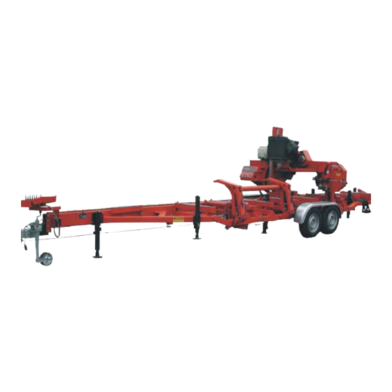
Specifications Log Capacity SECTION 8 SPECIFICATIONS Log Capacity See Table 8-1. The dimensions of logs that can be cut on the LT70 Series sawmills are listed below. LT70S LT70M LT70L LT70 WIDE Maximum Cutting Width 36,6” (73 cm) 36,6” (73 cm) 36,6”... - Page 150 Specifications Overall Dimensions See Figure 8-1. LT70L DH FIG. 8-2 60doc102619 Specifications...
- Page 151 Specifications Overall Dimensions See Figure 8-3. LT70L DH WIDE FIG. 8-4 Specifications 60doc102619...
- Page 152 Specifications Overall Dimensions See Figure 8-5. LT70L Super RYS. 8-6 See Table 8-2. LT70L 2780 kg Weight TABLE 8-2 Weight with trailer heaviest motor/engine option. 60doc102619 Specifications...
-
Page 153: Engine/Motor Specifications
TABLE 8-3 Use diesel fuel for D42. The electric motors supplied on Wood-Mizer sawmills carry a rating assigned by the motor manufacturer for the continuous duty operation of the motor, potentially, 24 hours per day, day after day. This rating is useful in sizing motors for use in applications like blowers for heating and ventilation that are never cycled off except for system maintenance. -
Page 154: Chains
Specifications Chains Chains See Table 8-6. The load capacity of the chains is listed below. Load Capacity According to ISO No 08A-1 Power Feed Chain 22700N Up/Down Chain 45400N TABLE 8-6 Lube System Specifications The blade lubricating oil specifications are listed below. Oil Type Manufacturer Freezing... -
Page 155: Belt Sizes
Specifications Belt Sizes Belt Sizes See Table 8-10. Belt sizes for the LT70 Series sawmills are shown. Description Belt Size Wood-Mizer Part # Motor Drive Belt ( E25 ) 3B/HB 089464 2462La Engine Drive Belt ( D42 ) 3B/HB 089464... -
Page 156: Hydraulic Blade Tensioner Componentssawdust Extractor Specifications8-8
Specifications Hydraulic Blade Tensioner ComponentsSawdust Extractor Specifications Hydraulic Blade Tensioner ComponentsSawdust Extractor Specifications Description Non-Return Valve HVR NW10MLED Hose DN-12 Hose DN-12 T-Pipe DT RNW10HL Connector VRNW10HL Elbow W90HROKO6HJ04 Hose 1/4” Elbow W90HROK04HJ Valve ECP 20/22B2 Connector 4-4F642E DM XS Throttle Valve VSG522.100000 Connector 4-4F42ED MXS TABLE 8-11... -
Page 157: Hydraulic Information
Hydraulic Information LT 40/70L DH Hydraulic Schematic SECTION 9 HYDRAULIC INFORMATION LT 40/70L DH Hydraulic Schematic FIG. 9-1 HYDRAULIC SCHEMATIC Hydraulic Information 60HDdoc102619... -
Page 158: Lt 40/70L Dh Hydraulic Hoses
Hydraulic Information LT 40/70L DH Hydraulic Hoses LT 40/70L DH Hydraulic Hoses Color LENGTH Application QTY. Wood-Mizer Code "A" Part No. 0,65m Hose 3/8” Section Link 089844 0,43m Hose 3/8” Section To Oil Flow Divider. 089845 Orange 2,8m Hose 3/8” Middle Log Clamp, IN/OUT Cylinder... - Page 159 EC declaration of conformity according to EC Machinery Directive 2006/42/EC, Annex II, 1.A Manufacturer: Wood-Mizer Industries Sp. z o.o. 114 Nagórna; 62- Tel. +48 63 26 26 000 This declaration of conformity is issued under the sole responsibility of the manufacturer.
Need help?
Do you have a question about the LT70L DH and is the answer not in the manual?
Questions and answers