Table of Contents
Advertisement
Advertisement
Table of Contents

Related Manuals for Wood-mizer LT40L DH


Summary of Contents for Wood-mizer LT40L DH
- Page 3 Wood-Mizer Sawmill ® Safety, Setup, Operation & Maintenance Manual LT40L DH rev. E7.00 Safety is our #1 concern! Read and understand all safety information and instructions before operating, setting up or maintaining this machine. Form #947 This is the original language...
- Page 4 Sawmill and Customer Identification Each Wood-Mizer sawmill has a 17-digit Vehicle Identification Number (VIN). See the figure below for VIN locations. See the chart for VIN description. V.I.N. LOCATIONS F9 017 F9 .01 V.I.N. DESCRIPTION...
- Page 5 Each sawmill is also identified with a model number which includes the base model and the engine/motor configuration. See the figure for a description of the model number. LT40 Engine/Motor Basic Sawmill I.D. Configuration MODEL NUMBER DESCRIPTION. When you pick up your mill, you will receive a customer number. Both the VIN and your customer number expedite our service to you.
-
Page 7: Table Of Contents
Table of Contents Section-Page General Contact Information Branches & Authorized Sales CentersWood-Mizer Locations (North and South America) SECTION 1 SAFETY & GENERAL INFORMATION Blade Handling..................1-2 Sawmill Setup..................1-2 Sawmill Operation..................1-3 Sawmill Maintenance ................1-6 Transporting the Sawmill ..............1-13 Belt Sizes ....................1-13 Blade Sizes ...................1-14 Cutting Capacity...................1-15 Engine/Motor Specifications ..............1-16 1.10... - Page 8 Table of Contents Section-Page Blade Guides ..................3-2 Sawdust Removal ...................3-2 Carriage Track, Wiper & Scrapers ............3-3 Vertical Mast Rails .................3-4 Drum Switches ..................3-4 Miscellaneous ..................3-5 Blade Tensioner..................3-6 Blade Wheel Belts ..................3-7 3.10 Blade Wheel Belts ..................3-7 3.11 Brake Strap Adjustment .................3-8 3.12 Drive Belt Adjustment................3-9 3.13...
- Page 9 Table of Contents Section-Page 5.15 Vertical Adjustment of Side Supports..........5-25 5.16 Clamp Stop/Stop Bolt Adjustment ............5-26 5.17 Saw Head Tilt ..................5-27 5.18 Blade Height Scale Adjustment............5-28 SECTION 6 HYDRAULIC INFORMATION LT 40/70L DH Hydraulic Schematic ............6-2 LT 40/70L DH Hydraulic Hoses ............6-3 Table of Contents SW-07doc0411183...
-
Page 10: General Contact Information
General Contact Information Getting Service Wood-Mizer is committed to providing you with the latest technology, best quality and strongest customer service available on the market today. We continually evaluate our customers’ needs to ensure we’re meeting current wood-processing demands. Your comments and suggestions are welcome. -
Page 11: Branches & Authorized Sales Centerswood-Mizer Locations (North And South America)
Branches & Authorized Sales CentersWood-Mizer Locations (North and South America) Branches & Authorized Sales CentersWood-Mizer Locations (North and South America) EUROPE UNITED STATES European Headquarters World Headquarters Wood-Mizer Industries Sp. z o.o. Wood-Mizer LLC Nagórna 114, 62-600 Koło, Poland 8180 West 10th Street Tel.: +48-63-26-26-000 Indianapolis,Indiana 46214-2400, Fax: +48-63-27-22-327 www.woodmizer.eu... - Page 12 Branches & Authorized Sales CentersWood-Mizer Locations (North and South America) CROATIA Krešimir Pregernik ITALY Pasquale Felice SERBIA Dragan Markov Pregimex d.o.o. Wood-Mizer Italia Srl Wood-Mizer Balkan d.o.o. S. Batušiæa 31, 10090 Zagreb Cda. Capoiaccio SN Svetosavska GA 3/3; P. Fah 25 Tel.:/Fax: +3851-38-94-668...
- Page 13 Brazil Headquarters Europe Headquarters Serving Brazil Serving Europe, Africa, West Asia Wood-Mizer do Brasil Wood-Mizer Industries Sp z o.o. Rua Dom Pedro 1, No: 205 Bairro: Sao Jose Nagorna 114 Ivoti/RS CEP:93.900-000 62-600 Kolo, Poland Tel: +55 51 9894-6461/ +55 21 8030-3338/ +55 51 Phone: +48.63.26.26.000...
-
Page 14: Safety & General Information
It is always the owner's responsibility to comply with all applicable federal, state and local laws, rules and regulations regarding the ownership, operation and towing of your Wood-Mizer sawmill. All Wood-Mizer mill owners are encouraged to become thoroughly familiar with these applicable laws and comply with them fully while using or towing the mill. -
Page 15: Blade Handling
Safety & General Information Blade Handling Blade Handling DANGER! Shut off the sawmill motorbefore changing the blade. Failure to do so will result in serious injury. WARNING! Always wear gloves and eye protection when handling bandsaw blades. Changing blades is safest when done by one person! Keep all other persons away from area when coiling, carrying or changing a blade. -
Page 16: Sawmill Operation
Safety & General Information Sawmill Operation Sawmill Operation DANGER! Make sure all guards and covers are in place and secured before operating or towing the sawmill. Failure to do so may result in serious injury. Be sure the blade housing and pulley covers are in place and secure. Use the safety retainer pin and cable to fasten blade housing covers. - Page 17 Safety & General Information Sawmill Operation WARNING! Never use the board return table as a platform to stand on. This table is designed and intended to assist in the removal of boards only. Standing on the table may result in serious injury. WARNING! Use ONLY water with the water lube accessory.
- Page 18 Safety & General Information Sawmill Operation CAUTION! Be careful when manually lowering the log loader. Do not drop the loader onto the ground or perform any action which might break the velocity fuse valves on the loader cylinders. These valves control hydraulic flow and are necessary to prevent the loading arm from collapsing during use.
-
Page 19: Sawmill Maintenance
Safety & General Information Sawmill Maintenance DANGER! Any maintenance or repair must be done with the power off (the plug must be taken out of the outlet).Maintain a clean and clear path for all necessary movement around the mill and lumber stacking areas. - Page 20 Safety & General Information Sawmill Maintenance links. CAUTION! Do not over-tension the up/down chain. Over-tensioning may lead to early failure of the gear reducer. CAUTION! Do not overtighten the feed chain. Damage to the power feed motor may result. CAUTION! Do not overtighten the contact set screws on the hydraulic valve assembly.
- Page 21 Safety & General Information Sawmill Maintenance See Table 1-1. Pictogram decals used to warn and inform the user about danger in the LT40. TABLE 1-1 Decal View W-M No. Description 096317 CAUTION! Read thoroughly the manual before operating the machine. Observe all safety instructions and rules when operating the sawmill.
- Page 22 Safety & General Information Sawmill Maintenance TABLE 1-1 099223 Blade tension - See manual. 099223 099221 CAUTION! Keep all persons a safe distance away from work area when operating the machine. 099221 098176 CAUTION! Keep away from debarker blade! 098176 doc041118 Safety &...
- Page 23 Safety & General Information Sawmill Maintenance TABLE 1-1 096316 CAUTION! Do not open or close the electric box when the switch is not in the “0” position. 096319 CAUTION! Disconnect power supply before opening the box. 099222 CAUTION! Sawdust outlet. Protect eyes! 099542 CAUTION! Trailer.
- Page 24 Safety & General Information Sawmill Maintenance TABLE 1-1 512235 Clean chain from sawdust every 50 hours of operation or once a week. 512235 512157 Lubricate chain every 50 hours of operation or once a week. 512157 S12004G CAUTION! Always wear safety goggles when operating the sawmill! S12005G CAUTION! Always wear protective ear...
- Page 25 Safety & General Information Sawmill Maintenance TABLE 1-1 P11789 Aligning the blade on the wheels P85070 CE safety certification 099401 Russian safety certification 099401 S20097E 2930 RPM - motor rotation direction 2930 RPM S20097E Safety & General Information doc041118 1-12...
-
Page 26: Transporting The Sawmill
2. Make sure the overrunning brake is functioning properly. Adjust if necessary. 3. Check to see tires are properly inflated. Belt Sizes See Table 1-2. Belt sizes for the LT40 sawmills are shown. Description Belt Size Wood-Mizer Part # Blade Pulley Belts P04185 Power Feed Drive Belt AC AX13X1000... -
Page 27: Blade Sizes
Blade Sizes Blade Sizes See Table 1-3. Wood-Mizer offers three types of blades to provide efficient sawing for all models of sawmills. The engine/motor size of your sawmill and the type of wood you saw should determine which blade you choose for optimum performance. -
Page 28: Cutting Capacity
LT40S DH with Optional 24' Bed Extension 91,5 cm (36") 13,7 m (45') LT40M DH with Optional 24' Bed Extension LT40L DH 91,5 cm (36") 8,4m TABLE 1-4 Maximum log capacity for a basic mill is 4400 lbs. (1996 Kg). -
Page 29: Engine/Motor Specifications
TABLE 1-6 Use diesel fuel for D40. The electric motors supplied on Wood-Mizer sawmills carry a rating assigned by the motor manufacturer for the continuous duty operation of the motor, potentially, 24 hours per day, day after day. This rating is useful in sizing motors for use in applications like blowers for heating and ventilation that are never cycled off except for system maintenance. -
Page 30: Overall Dimensions
Safety & General Information Overall Dimensions 1.10 Overall Dimensions See Table 1-9. The overall dimensions of the Wood-Mizer LT40S/M/L DH sawmills are listed below. Model With Weight Weight Length Width Height (Operating Position w/Trailer with Loading Arms) LT40S DH 6,7 m... -
Page 31: Dust Extractor Specifications
Safety & General Information Dust Extractor Specifications 1.13 Dust Extractor Specifications See Table 1-12. Specifications of the dust extractors used on the resaw for each saw head are listed below. Airflow 1200 m 3937ft Inlet diameter 100 mm (5.9”) Motor power 1,5 kW Number of sacks 1 pcs... -
Page 32: Components
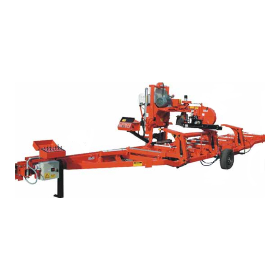
Safety & General Information Components 1.14 Components See Figure 1-1. The major components of the Wood-Mizer LT40L DH are shown below. FIG. 1-1 Hydraulic Control Box Control Box Power Cord Connection Box Motor Hydraulic Log Loader Blade Tensioner Side Support... - Page 33 Safety & General Information Components See Figure 1-2. The Hydraulic Pump Electrical Diagram is shown below. FIG. 1-2 Safety & General Information doc041118 1-20...
-
Page 34: Setup & Operation
Setup & Operation Sawmill Setup SECTION 2 SETUP & OPERATION Sawmill Setup IMPORTANT! Before starting to use the sawmill you have to meet the following conditions: Set up the sawmill on firm and level ground. The sawmill can be operated with the sawdust collection system only. ... -
Page 35: Stationary Sawmill Setup
Setup & Operation Stationary Sawmill Setup Stationary Sawmill Setup See Figure 2-1. Prepare a firm, level area where the sawmill can be anchored. There should be enough room around the sawmill for operators, sawdust removal, log loading and board removal. A cement pad with 5/8”... - Page 36 Setup & Operation Stationary Sawmill Setup See Figure 2-2. Bed Rail Side Support Sm0130b FIG. 2-2 doc041118 Setup & Operation...
-
Page 37: Portable Sawmill Setup
Setup & Operation Portable Sawmill Setup Portable Sawmill Setup WARNING! Do not set up the mill on ground with more than a 10 degree incline. If setup on an incline is necessary, put blocks under one side of the mill or dig out areas for outrigger legs to keep mill level. Setting up the mill on an incline could cause it to tip over, resulting in serious personal injury. - Page 38 Setup & Operation Portable Sawmill Setup See Figure 2-3. Adjustment Bolt Outrigger Leg Travel Lock Pin Locking Pin 80_008 FIG. 2-3. OUTRIGGER ADJUSTMENT. CAUTION! If setup sawmill on a boggy terrain (such as deep mud or sand) place the board or metal plate under each outrigger leg to prevent it from sinking.
- Page 39 Setup & Operation Portable Sawmill Setup 3. Unhook the carriage safety chain, located at the bottom of the vertical mast. 4. Turn the key switch on the control panel to the accessory (#3) position to enable accessories. Use the up/down switch on the control panel to raise the cutting head from the carriage rest pin. Remove the locking pin and swing the rest pin down below bed level.
-
Page 40: Middle Track Cover
Setup & Operation Middle Track Cover Middle Track Cover Before operating the sawmill do as follows: 1. Clean the upper and lower rails to remove any sawdust and rust preventives. 2. Unbolt and remove the middle track cover from its storage position. 3. -
Page 41: Replacing The Blade
Setup & Operation Replacing The Blade Replacing The Blade DANGER! Always disengage the blade and shut off the sawmill engine before changing the blade. Failure to do so will result in serious injury. WARNING! Always wear gloves and eye protection when handling bandsaw blades. -
Page 42: Tensioning The Blade
Setup & Operation Tensioning The Blade Tensioning The Blade See Figure 2-6. Tension the blade by turning the hydraulic tensioning handle clockwise until the tension gauge indicates the recommended tension. Blade Tensioner Gauge Blade Tensioner Handle Cant Control SM0243 FIG. 2-6 See Table 2-1. -
Page 43: Tracking The Blade
Setup & Operation Tracking The Blade Tracking The Blade 1. Make sure the middle blade housing cover is closed and all persons are clear of the open side of the saw head. 2. While the main switch is on, turn the key switch to #2 position. 3. -
Page 44: Starting The Motor
Setup & Operation Starting The Motor IMPORTANT! After aligning the blade on the wheels, always double-check the blade guide spacing and location. (See Section 5 for more information.) Starting The Motor See the appropriate manual supplied with your specific motor configuration for starting and operating instructions. - Page 45 Setup & Operation Starting The Motor After installation, test the sawmill for proper motor rotation. If rotation is incorrect, turn the motor off pushing the STOP button located on the control box. Turn the main switch on the starter box to the OFF (“0”) position. Disconnect the power cord on the left side of the starter box.
-
Page 46: Hydraulic Control Operation
Setup & Operation Hydraulic Control Operation Hydraulic Control Operation The hydraulic control levers become operational when the main switch located on the starter box is in the “#1” position and the contacts at the bottom of the carriage touch the power strip on the frame tube. - Page 47 Setup & Operation Hydraulic Control Operation See Figure 2-8. Hydraulic units have six control levers to load, clamp, turn and level logs. Front Middle Toeboard Toeboard Rear Toeboard Turner up/down Turner Front clamp in/out Loader Front clamp up/down Main clamp in/out Rear clamp 80_pulpit_hyd...
- Page 48 Setup & Operation Hydraulic Control Operation 1. Move the clamp out and down so it will not get in the way of logs being loaded onto the bed. Lower the clamp in/out lever to move the clamp out toward the loading side of the sawmill. Lower the clamp up/down lever to lower the clamp below bed level.
-
Page 49: Loading, Turning, And Clamping Logs
Setup & Operation Loading, Turning, And Clamping Logs 2.10 Loading, Turning, And Clamping Logs CAUTION! Be sure the pivot rails, turning arm, clamp, and toe boards are below bed level before loading a log onto the bed. Failure to do so may result in machine damage or cause misalignment. - Page 50 Setup & Operation Loading, Turning, And Clamping Logs To Turn Logs 1. Raise the turner lever to engage the log turner arm. Let the arm rise until it touches the log and starts to turn it. 2. Spin the log against the side supports until it is turned the way you want it for the first cut. If you want to turn the log more, do the following steps.
- Page 51 Setup & Operation Loading, Turning, And Clamping Logs To Clamp Logs 1. Raise the clamp in/out lever and clamp the log against the side supports. 2. Lower the turner lever until the turner arm falls below the bed. 3. When the turner arm is lowered all the way, the side supports will begin to lower. Back the clamp off slightly, and let the side supports come down until they are positioned below the level of your first few cuts.
-
Page 52: Up/Down Operation
Setup & Operation Up/Down Operation 2.11 Up/Down Operation 1. Install a blade, if needed, and check for correct blade tension (See Section 2.6). 2. Set the cutting head to the desired height. (The blade height scale shows the height of the blade above the bed rails.) See Figure 2-9. -
Page 53: Blade Guide Arm Operation
Setup & Operation Blade Guide Arm Operation 2.12 Blade Guide Arm Operation 1. Look down the length of the log to see its maximum width. The outer blade guide should be adjusted to clear the widest section of the log by less than 1" (25.4 mm). 2. -
Page 54: Clutch/Brake Operation
Setup & Operation Clutch/Brake Operation 2.13 Clutch/Brake Operation NOTE: If your sawmill is equipped with the Remote Option, see the option manual for clutch/brake operation. 1. Clear any loose objects from the area of the blade, motor, and drive belt. 2. - Page 55 Setup & Operation Clutch/Brake Operation 4. To engage the blade, pull the lever down until it locks in the down position. This engages the drive mechanism, releases the blade brake, and increases the engine speed to full throttle. To disengage the blade, raise the clutch/brake lever to the up position. This disengages the drive belt, engages the blade brake, and returns the engine to idle.
-
Page 56: Power Feed Operation
Setup & Operation Power Feed Operation 2.14 Power Feed Operation See Figure 2-13. The power feed system moves the carriage forward and backward by using two switches on the control panel. Carriage Forward Forward Feed Rate Carriage Reverse 3H0280a1 FIG. 2-13 Carriage Feed Rate The carriage feed rate switch controls the speed at which the carriage travels forward. - Page 57 Setup & Operation Power Feed Operation WARNING! Be sure the power feed switch is in the neutral position before turning the key switch to the (#2) or (#1) position. This prevents accidental carriage movement. which may cause serious injury or death.
-
Page 58: Cutting The Log
Cutting The Log 2.15 Cutting The Log The following steps guide you through normal operation of the Wood-Mizer sawmill. 1. Once the log is placed where you want it and clamped firmly, turn the key switch to the accessory (#2) position. -
Page 59: Edging
27 - 29 mm for each board. 2.16 Edging The following steps guide you through edging boards on the Wood-Mizer sawmill. 1. Raise the side supports to 1/2 the height of the flitches, or the boards that need to be edged. -
Page 60: Optional Cutting Procedure For Super Series Mills
Setup & Operation Optional Cutting Procedure for Super Series Mills 2.17 Optional Cutting Procedure for Super Series Mills In order to achieve maximum production rates with Super Series mills; it may be desirable to leave the blade engaged when returning the carriage. (Normal operation procedures recommend disengaging the blade before returning the carriage for maximum blade life and fuel economy.) DANGER! If leaving the blade engaged for maximum production rates,... - Page 61 Setup & Operation Blade Height Scale Blade Height Indicator The blade height indicator has two horizontal, red lines on both sides. Readings should be taken with eyes level with the indicator, when the two red lines are in line. This will allow to avoid the parallax error (different scale readings depending on the angle of vision).
- Page 62 Setup & Operation Blade Height Scale Example: You want to cut 1" (25 mm) random width boards from a log. Position the blade for the first cut. Move the carriage to an even measurement on the inch scale. Make a trim cut. Return the carriage for the second cut and lower it 1 1/8"...
-
Page 63: Water Lube Operation
Setup & Operation Water Lube Operation 2.19 Water Lube Operation See Figure 2-15. The Water Lube System keeps the blade clean. Water flows from a 5-gallon (18.9 liter) bottle through a hose to the blade guide where the blade enters the log. A valve in the bottle cap controls the amount of water flow. -
Page 64: Preparing The Sawmill For Towing
(#0). 2.20 Preparing The Sawmill For Towing The Wood-Mizer trailer package makes transporting your sawmill easy and convenient. To get your sawmill ready for towing, follow these instructions. 1. Move the saw carriage to the front end of the sawmill. Raise the rear outriggers. - Page 65 Setup & Operation Preparing The Sawmill For Towing CAUTION! Move the hydraulic clamp and turner to provide maximum ground clearance before towing. Failure to do so may result in damage to the sawmill. 3. Move the carriage forward to the travel position over the rear bed rail. 4.
- Page 66 Setup & Operation Preparing The Sawmill For Towing See Figure 2-18. Loosen jam nut and turn bolt to raise or lower stop bolt FIG. 2-18 9. Use the hydraulic controls to raise the log turner and loader as high as they will go. Manually lift the loader and hook the loader chains to the sawmill frame.
- Page 67 Setup & Operation Preparing The Sawmill For Towing 12. Remove all loose objects from the bed of the mill. Store the outrigger jack handle in the bracket provided on the rear/loading-side outrigger guide. Reel in the winch cable. Remove the winch handle.
-
Page 68: Maintenance
Maintenance Wear Life SECTION 3 MAINTENANCE This section lists the maintenance procedures that need to be performed. The Short Interval Maintenance Schedule lists procedures that need to be performed every 4, 8 or 25 hours.The Maintenance Log lists procedures that need to be performed every 50, 100, 200, or 1000 hours. -
Page 69: Blade Guides
Maintenance Blade Guides Blade Guides 1. Check the rollers for performance and wear every blade change. Make sure the rollers are clean and spinning freely. If not, rebuild them. Replace any rollers which have worn smooth or have become cone shaped. See The LT40S/M DH Parts manual for blade guide rebuild kits and complete roller assemblies. -
Page 70: Carriage Track, Wiper & Scrapers
Maintenance Carriage Track, Wiper & Scrapers Carriage Track, Wiper & Scrapers See Figure 3-2. 1. Clean the upper and lower track rails to remove any sawdust and sap buildup every eight hours of operation. Lubricate the lower track rail by wiping it with Dexron III ATF. 2. -
Page 71: Vertical Mast Rails
Lubricate the up/down and power feed drum switch contacts inside the control panel every fifty hours of operation. Use only contact grease supplied by Wood-Mizer. Remove the control panel cover. Use a cotton swab to apply grease to the switch contact ends. -
Page 72: Miscellaneous
Maintenance Miscellaneous Miscellaneous 1. Apply a thin film of a grade lithium grease to the blade guide arm every fifty hours of operation to help prevent it from rusting. 2. Grease the clamp mechanism, loading arm, and side supports with a grade lithium grease every 50 hours of operation. -
Page 73: Blade Tensioner
Maintenance Blade Tensioner Blade Tensioner 1. Lubricate the chrome rods of the tensioner system with a heavy duty teflon spray lubricant every 50 hours of operation. 2. Lubricate the tensioner screw handle with a grade lithium grease as needed. See Figure 3-3. FIG. -
Page 74: Blade Wheel Belts
Maintenance Blade Wheel Belts o-ring with the plug. Manually extend the rear piston (the front piston should remain extended). Use a small funnel or cup to completely fill the block with hydraulic fluid. When full, place the fill plug in the fill plug hole and thread 1-2 turns. Manually push the rear piston all the way in to allow excess oil and air to bleed from system through the plug. -
Page 75: Brake Strap Adjustment
Maintenance Brake Strap Adjustment 3.11 Brake Strap Adjustment Check the brake strap for wear every 200 hours of operation. Replace if damaged or worn. Also check and adjust the brake strap if the blade does not stop quickly, unusual sounds occur when the brake is applied, or a sudden change is noticed in the clutch handle position when the clutch is disengaged. -
Page 76: Drive Belt Adjustment
Maintenance Drive Belt Adjustment 3.12 Drive Belt Adjustment WARNING! Do not for any reason adjust the engine drive belts or belt support bracket with the engine running. Doing so may result in serious injury. See Table 3-2. Check the drive belt tension after the first 20 hours, and every 50 hours thereafter. - Page 77 Maintenance Drive Belt Adjustment See Figure 3-7. Hold top portion with wrench Turn bottom jam nut clockwise to tighten belt 3H0505-3 FIG. 3-7 4. Gas/Diesel Engines Only: After tensioning the drive belt, check throttle cable tension and adjust if necessary. The throttle cable should be tensioned just enough so that the engine revs as soon as the clutch/brake handle is engaged.
- Page 78 Maintenance Drive Belt Adjustment Adjust the drive belt support as needed. The drive belt support is designed to extend belt life. The bracket should be adjusted to NOT touch the drive belt when the clutch handle is engaged (down position), AND to hold the drive belt away from the engine pulley when the clutch handle is disengaged (up position).
-
Page 79: Clutch Handle Adjustment
Maintenance Clutch Handle Adjustment 3.13 Clutch Handle Adjustment After the drive belts and brake strap are properly adjusted, the clutch handle should lock in the down position when the drive belts are engaged. If the clutch handle does not stay locked, adjust the handle turnbuckle. -
Page 80: Hydraulic System
Maintenance Hydraulic System 3.14 Hydraulic System 1. Check the hydraulic fluid level every 50 hours of operation. Add fluid as necessary. The level in the hydraulic pump should be 19mm from the top with all cylinders collapsed. If humidity is a problem or the mill is used outside in humid weather, drain and replace two quarts (.95 liters) of fluid every six months. -
Page 81: Drive Bearing
Maintenance Drive Bearing 3.15 Drive Bearing Refill the fluid in the drive-side cylinder bearing housing every 500 hours of operation. Remove the top and bottom oil plugs. Pour an Automatic Transmission Fluid (ATF, SAE 30) into the top hole until it begins to flow from the bottom hole. Reinstall the square oil plug to the bottom hole and the vented oil plug to the top hole. -
Page 82: Up/Down System
Maintenance Up/Down System 3.16 Up/Down System Up/Down Gear Reducer Shaft Bearing FIG. 3-11 1. Super model up/down systems feature a spring loaded belt design. Belt tension is automatically maintained and requires no adjustment. Replace the belt when adequate belt tension can no longer be obtained. WARNING! Always secure the cutting head with a chain or a brace before removing the up/down motor belt. - Page 83 Maintenance Up/Down System See Figure 3-12. FIG. 3-12 Maintenance HDSdoc041118 3-16...
-
Page 84: Power Feed
Maintenance Power Feed 3.17 Power Feed 1. Adjust the power feed belt as needed. When the power feed belt gets loose, it will begin slipping. This causes the carriage to not move forward when cutting. To retighten the belt: See Figure 3-13. Remove the four cover bolts and belt cover and measure the belt tension. - Page 85 Maintenance Power Feed See Figure 3-14. 3H0018B Feed Chain Adjustment Nuts FIG. 3-14 Maintenance HDSdoc041118 3-18...
- Page 86 LT40 Series A/DH Short Interval Maintenance Schedule (Check engine and option manuals for additional maintenance procedures) PROCEDURE MANUAL REFERENCE EVERY BLADE CHANGE Check Blade Guide Roller Performance See Section 3.2 Remove Excess Sawdust From Blade Wheel Housings And Sawdust Chute See Section 3.3 Check Blade Screw See Section 3.2...
- Page 87 WOOD-MIZER LT40 SERIES A/DH MAINTENANCE LOG (Check Engine And Option Manuals For Additional Maintenance Procedures) PROCEDURE MANUAL TOTAL HOURS OF OPERATION REFERENCE FILL IN THE DATE AND THE MACHINE HOURS AS YOU PERFORM EACH PROCEDURE. A SHADED BOX INDICATES MAINTENANCE IS NOT NEEDED AT THIS TIME.
- Page 88 WOOD-MIZER LT40 SERIES A/DH MAINTENANCE LOG (Check Engine And Option Manuals For Additional Maintenance Procedures) PROCEDURE MANUAL TOTAL HOURS OF OPERATION REFERENCE FILL IN THE DATE AND THE MACHINE HOURS AS YOU PERFORM EACH PROCEDURE. A SHADED BOX INDICATES MAINTENANCE IS NOT NEEDED AT THIS TIME.
- Page 89 WOOD-MIZER LT40 SERIES A/DH MAINTENANCE LOG (Check Engine And Option Manuals For Additional Maintenance Procedures) PROCEDURE MANUAL TOTAL HOURS OF OPERATION REFERENCE FILL IN THE DATE AND THE MACHINE HOURS AS YOU PERFORM EACH PROCEDURE. A SHADED BOX INDICATES MAINTENANCE IS NOT NEEDED AT THIS TIME.
- Page 90 WOOD-MIZER LT40 SERIES A/DH MAINTENANCE LOG (Check Engine And Option Manuals For Additional Maintenance Procedures) PROCEDURE MANUAL TOTAL HOURS OF OPERATION REFERENCE FILL IN THE DATE AND THE MACHINE HOURS AS YOU PERFORM EACH PROCEDURE. A SHADED BOX INDICATES MAINTENANCE IS NOT NEEDED AT THIS TIME.
-
Page 91: Troubleshooting Guide
Troubleshooting Guide Sawing Problems SECTION 4 TROUBLESHOOTING GUIDE Sawing Problems PROBLEM CAUSE SOLUTION Blades Dull Quickly Dirty logs Clean or debark logs, especially on entry side of the cut When grinding teeth, heating Grind just enough metal to restore too much and causing teeth to sharpness to the teeth. - Page 92 Troubleshooting Guide Sawing Problems PROBLEM CAUSE SOLUTION Boards Thick Or Thin On Stress in log which causes log After log has been squared, take Ends Or Middle Of Board. to not lay flat on the bed. equal cuts off opposing sides. Take a board off the top.
-
Page 93: Electrical Problems
Troubleshooting Guide Electrical Problems Electrical Problems PROBLEM CAUSE SOLUTION Up/down Excessively Slow. Vertical wear pads too tight. Adjust pads. Up/down belt loose. Adjust belt to be as loose as possible without slipping Up/down Or Power Feed Worn/dirty contacts in drum Replace switch or remove Motors Do Not Work. -
Page 94: Power Feed Problems
Drum switch is dirty. Clean drum switch and lubricate Speeds Or Does Not Move with contact grease supplied by Until Speed Is Above Halfway Wood-Mizer. Mark. Drum switch contacts are bad Check that contacts are in good condition and positively close circuit. - Page 95 Troubleshooting Guide Power Feed Problems PROBLEM CAUSE SOLUTION Power Feed Motor Overheats. Middle track oiler is dragging. Clean middle track oiler and lubricate with 30-weight oil or ATF (Automatic Transmission Fluid) such as Dexron II. Allow motor to cool before restarting. Ground is not level.
-
Page 96: Hydraulic Problems
Troubleshooting Guide Hydraulic Problems Hydraulic Problems PROBLEM CAUSE SOLUTION You Can Actuate Any Carriage not positioned Make sure carriage contact Hydraulic Handle, But Get No properly to provide power to bracket is adjusted far enough Response From The Pump. the pump forward for battery positive contact to touch 6ft. - Page 97 Troubleshooting Guide Hydraulic Problems You Can Get Response From Valve assembly switch Locate the valve switch at the the Pump By Actuating All contacts are not properly bottom of the valve assembly. Use But One or Two Handles adjusted a 3MM allen wrench to loosen the set screw on each of the five switch contacts.
- Page 98 Troubleshooting Guide Hydraulic Problems PROBLEM CAUSE SOLUTION Pump Motor Runs With Little Low fluid level Check fluid level. Add an Or No Response From The all-season hydraulic fluid such as Cylinders Amoco Rycon Oil MV or Mobil Multipurpose ATF (automatic transmission fluid) until level is 4 - 4 1/2"...
- Page 99 Troubleshooting Guide Hydraulic Problems PROBLEM CAUSE SOLUTION Hydraulic Side Supports Go Dirt in sequence valve Remove sequence valves and Down Before Or At Same clean thoroughly with kerosene. Time As Log Turner NOTE: Be sure to reassemble the valve and install it in its original position on the cylinder.
-
Page 100: Motor And Drive Pulleys Alignment
Troubleshooting Guide Motor and Drive Pulleys Alignment Motor and Drive Pulleys Alignment 1. Install the drive belt. 2. Use a straight edge to align the engine/motor pulley to the drive pulley. 3. Check front-to-back movement of the engine does not exceed 6,5 mm (1/4"). Tighten the motor mount U-bolts if necessary. -
Page 101: Hydraulic Pressure Test
Troubleshooting Guide Hydraulic Pressure Test 3. Make sure the middle track oiler is free of sawdust buildup. 4. Make sure the power feed chain is not stiff from rust. Also make sure the chain is not too tight. 5. Check the power feed shaft. Visually inspect the bearings. The shaft should move neither in or out nor side to side. -
Page 102: Sawmill Alignment
SECTION 5 SAWMILL ALIGNMENT Pre-Alignment Procedures The Wood-Mizer sawmill is factory aligned. Two alignment procedures are available to realign the sawmill if necessary. The Routine Alignment instructions should be performed as necessary to solve sawing problems not related to blade performance. -
Page 103: Frame Setup
LT40M DH: Adjust the two end outriggers on the main frame tube down just enough to lift weight from the trailer tire. LT40L DH. Adjust front outriggers on the main frame tube down just enough to lift weight from the trailer tires. -
Page 104: Blade Installation And Alignment
Sawmill Alignment Blade Installation And Alignment Blade Installation And Alignment See Figure 5-1. Install a blade and apply the appropriate tension (See Section 2.4). The blade tension is adjusted with the tension handle shown below. Blade Tensioner Gauge Blade Tensioner Handle Cant Control SM0243... - Page 105 Sawmill Alignment Blade Installation And Alignment (±1/16 [1.5 mm]). Do not let the teeth ride on the wheels. SM0044D 3.0 mm (0.12”) ± 1 mm (0.04”) 4.5 mm (0.18”) 1 1/4" ± 1 mm (0.04”) Blade 1 1/2" Blade FIG. 5-2 To adjust where the blade travels on the idle-side blade wheel, use the cant control shown in Figure 5-1.
- Page 106 Sawmill Alignment Blade Installation And Alignment See Figure 5-3. For horizontal adjustment, use the horizontal adjustment nuts. If the blade is running too far back on the drive-side blade wheel, locate the long U-bolt on the right which mounts the bearing housing to the mounting plates. Loosen the hex nuts on the U-bolt (on the back side of the back plate).
-
Page 107: Saw Head Slide Pad Adjustment
Sawmill Alignment Saw Head Slide Pad Adjustment Saw Head Slide Pad Adjustment There are eight nylon pads positioned between the saw head frame and vertical mast. The spacing of the pads is factory set and rarely needs adjusting. To check the pad spacing, perform the following steps. - Page 108 Sawmill Alignment Saw Head Slide Pad Adjustment 1. Raise the saw head to the top of the vertical mast and secure the saw head with a chain at the top, or shim it underneath. Check the top set of four pads.The outer two pads should be touching the mast rails.
-
Page 109: Adjusting The Lower Track Rollers
Sawmill Alignment Adjusting The Lower Track Rollers Adjusting The Lower Track Rollers See Figure 5-5. Making these adjustments correctly will give you square cuts and accurate dimensions across the width of your boards. 1. Using the feed controls, move the saw carriage so that the blade is positioned over the front pivot end rail. - Page 110 Sawmill Alignment Adjusting The Lower Track Rollers 6. Open the adjustable blade guide arm to within 1/2" (15 mm) of full open. 7. Move the carriage back to the front pivot end rail. Raise the cutting head until the bottom of the blade is 17"...
-
Page 111: Adjusting Bed Rails To The Blade
Sawmill Alignment Adjusting Bed Rails To The Blade Adjusting Bed Rails To The Blade 1. Move the vertical clamp to its lowest position. Before using the clamp tube as a reference to set the blade, make sure it is level. 2. - Page 112 Sawmill Alignment Adjusting Bed Rails To The Blade 5. Move the saw head back to power the hydraulics and move the clamp so it is 10" from the clamp stop. Move the saw head forward until it is positioned over the clamp. Raise the saw head until the blade measures 15 5/16"...
- Page 113 Sawmill Alignment Adjusting Bed Rails To The Blade See Figure 5-9. Optional bed rail (angled) to blade to blade Inner Height Outer Height Adjustment Nut Adjustment Bolt RYS. 5-9 11. Loosen the jam nut and turn the outer adjustment bolt to adjust the height of the outer end of the pivot rail.
- Page 114 Sawmill Alignment Adjusting Bed Rails To The Blade See Figure 5-10. FIG. 5-10 See Figure 5-11. Optional bed rail (angled) Blade Bed rails Clamp bolt Clamp bolt Adjustment Adjustment bolt Adjustment bolt bolt SM0064_D RYS. 5-11 14. Loosen the bed rail clamping bolts and turn the adjustment bolts to move the bed rails to the blade if necessary.
-
Page 115: Blade Guide Arm Vertical Adjustment
Sawmill Alignment Blade Guide Arm Vertical Adjustment Blade Guide Arm Vertical Adjustment 1. Move the saw head so that the blade guide arm is directly over a bed rail. 2. Adjust the blade guide arm out to within 1/2" (15 mm) of full open. 3. - Page 116 Sawmill Alignment Blade Guide Arm Vertical Adjustment 6. The rollers are mounted on cam bolts that raise or lower the arm when turned. To adjust the rollers, locate the cam bolt head inside the housing and turn until the arm is lowered or raised as needed.
-
Page 117: Blade Guide Arm Horizontal Adjustment
Sawmill Alignment Blade Guide Arm Horizontal Adjustment Blade Guide Arm Horizontal Adjustment 1. Put the blade guide assembly back in the arm (if you took it out). Put the assembly back so that the flanged collar on the roller is about 1/8" (3.0 mm) from the back of the blade when the throat is 1/2"... - Page 118 Sawmill Alignment Blade Guide Arm Horizontal Adjustment See Figure 5-14. Adjustment Nuts Adjustment Nuts SM0066 FIG. 5-14 4. Adjusting the outside two rollers (furthest from the arm motor) inward will cause the flange to move away from the blade. 5. Adjusting the two outside rollers outward will cause the flange to move toward the blade. 6.
-
Page 119: Aligning The Blade Guides
Aligning the Blade Guides Aligning the Blade Guides Each Wood-Mizer sawmill has two blade guide assemblies that help the blade maintain a straight cut. The two blade guide assemblies are positioned on the saw head to guide the blade on each side of the material being cut. -
Page 120: Blade Deflection
Sawmill Alignment Blade Deflection 5.10 Blade Deflection Perform the following steps to achieve proper blade deflection with the blade guides. 1. Raise the carriage until the blade is 15" (375 mm) above a bed rail. Measure the actual distance with a tape from the top of the rail to the bottom of the blade. 2. -
Page 121: Blade Guide Vertical Tilt Adjustment
Sawmill Alignment Blade Guide Vertical Tilt Adjustment 5.11 Blade Guide Vertical Tilt Adjustment Check that the blade guide does not tilt the blade up or down. A Blade Guide Alignment Tool (BGAT) is provided to help you measure the vertical tilt of the blade. 1. - Page 122 Sawmill Alignment Blade Guide Vertical Tilt Adjustment See Figure 5-17. Loosen jam nuts and turn screws to tilt roller up or down SM0070 FIG. 5-17 8. Move the carriage forward so the back end of the tool is over the bed rail. 9.
-
Page 123: Blade Guide Spacing
Sawmill Alignment Blade Guide Spacing 5.12 Blade Guide Spacing HINT: When adjusting blade guide spacing, loosen the top set screw and one side set screw only. This will ensure horizontal and vertical tilt adjustments are maintained when the set screws are retightened. 1. -
Page 124: Horizontal Tilt Adjustment
Sawmill Alignment Horizontal Tilt Adjustment 5.13 Horizontal Tilt Adjustment 1. Finally, both blade guides must be tilted horizontally. Adjust the blade guide arm halfway See Figure 5-19. FIG. 5-19 2. Place the Blade Guide Alignment Tool against the face of the outer blade guide roller. 3. -
Page 125: Horizontal Adjustment Of Side Supports
Sawmill Alignment Horizontal Adjustment of Side Supports 5.14 Horizontal Adjustment of Side Supports Logs and boards are clamped against the side supports when sawing. The side supports must be square to the bed to ensure square lumber. 1. Swing the side support down. 2. -
Page 126: Vertical Adjustment Of Side Supports
Sawmill Alignment Vertical Adjustment of Side Supports 5.15 Vertical Adjustment of Side Supports 1. Place a flat board across the bed rails. 2. Swing a side support up so that it is vertical. 3. Pull back at the top of the support to eliminate slack as if a log were being clamped against it. -
Page 127: Clamp Stop/Stop Bolt Adjustment
Sawmill Alignment Clamp Stop/Stop Bolt Adjustment 5.16 Clamp Stop/Stop Bolt Adjustment 1. Once the side supports are aligned, pivot them down to their horizontal position. 2. Tie a string across the face of the side supports. See Figure 5-22. 3. Loosen the clamp stop bolts and adjust the clamp stop until it touches the string. Loosen the jam nut and adjust the bolt on the middle-rear bed rail until it touches the string. -
Page 128: Saw Head Tilt
Sawmill Alignment Saw Head Tilt 5.17 Saw Head Tilt As the blade enters a wide log or cant, the outside of the saw head will drop down slightly. To compensate for the drop, use the lower track roller horizontal bolts to raise the outside of the saw head 1/16"... -
Page 129: Blade Height Scale Adjustment
Sawmill Alignment Blade Height Scale Adjustment 5.18 Blade Height Scale Adjustment After the entire sawmill has been aligned and all adjustments made, check that the blade height scale indicates the true distance from the blade to the bed rails. 1. Move the saw head so the blade is positioned directly above one of the bed rails. Measure from the bottom edge on a down-set tooth of the blade to the top of the bed rail (or stainless steel sleeve if applicable). -
Page 130: Hydraulic Information
Hydraulic Information SECTION 6 HYDRAULIC INFORMATION HDSdoc041118 Hydraulic Information... -
Page 131: Lt 40/70L Dh Hydraulic Schematic
Hydraulic Information LT 40/70L DH Hydraulic Schematic LT 40/70L DH Hydraulic Schematic FIG. 6-1 HYDRAULIC SCHEMATIC. Hydraulic Information HDSdoc041118... -
Page 132: Lt 40/70L Dh Hydraulic Hoses
Hydraulic Information LT 40/70L DH Hydraulic Hoses LT 40/70L DH Hydraulic Hoses Color LENGTH Application QTY. Wood-Mizer Code "A" Part No. 0,65m Hose 3/8” Section Link 089844 0,43m Hose 3/8” Section To Oil Flow Divider. 089845 Orange 2,8m Hose 3/8” Middle Log Clamp, IN/OUT Cylinder... - Page 133 EC declaration of conformity according to EC Machinery Directive 2006/42/EC, Annex II, 1.A Manufacturer: Wood-Mizer Industries Sp. z o. o. Nagórna 114; 62- , Poland That the following described machine in our delivered version complies with the appropriate basic safety and health requirements of the EC Machinery Directive 2006/42/EC based on its design and type, as brought into circulation by us.
Need help?
Do you have a question about the LT40L DH and is the answer not in the manual?
Questions and answers