
Related Manuals for Wood-mizer HR150


Summary of Contents for Wood-mizer HR150
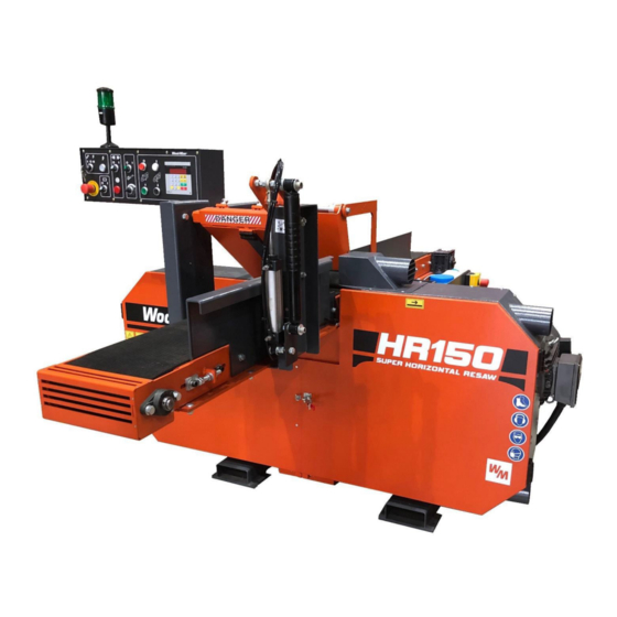
- Page 1 HR150 TWIN HEAD HORIZONTAL BAND RESAW OPERATION MANUAL • The operator must thoroughly read this manual before operation. • Keep this manual for future reference. Form 2386...
-
Page 2: Table Of Contents
CONTENTS GENERAL SAFETY RULES FOR WOODWORKING MACHINERY ..........1 SAFETY RULES FOR HORIZONTAL BAND RESAW ................ 4 MACHINE SPECIFICATIONS ......................8 LIFTING THE MACHINE ........................10 UNPACKING AND CHECKING CONTENTS ..................12 CLEANING THE MACHINE ........................ 13 INSTALLING MACHINE ........................14 LEGEND OF THE MACHINE (FRONT VIEW) .................. -
Page 3: General Safety Rules For Woodworking Machinery
GENERAL SAFETY RULES FOR WOODWORKING MACHINERY WARNING Do not attempt to operate until you have read thoroughly and understood completely all instructions, rules etc. contained in this manual. Failure to comply can result in accidents involving fire, electric shock, or serious personal injury. Keep this operation manual and review frequently for continuous safe operations. - Page 4 GENERAL SAFETY RULES FOR WOODWORKING MACHINERY 9. Do not force the machine. It will do the job better and be safer at the rate for which it was designed. 10. Use the right tools. Do not force the machine or attachments to do a job for which they were not designed for.
- Page 5 Use a wood dust collection system whenever possible. The HR150 Resaw is intended for sawing wood only. The machine must not be used for other purposes such as cutting ice, metal or any other materials.
-
Page 6: Safety Rules For Horizontal Band Resaw
SAFETY RULES FOR HORIZONTAL BAND RESAW 1. Do not attempt to remove any object from the conveyor belt when the machine is running. 2. The sawblade is very sharp. Care should be taken when replacing the sawblade. 3. Turn the power off before performing maintenance or servicing. 4. - Page 7 SAFETY RULES FOR HORIZONTAL BAND RESAW The blade tension should be released when the machine is not in use (e.g.: after a shift). There should be information on the machine that it is necessary to tension the blade before starting to use the machine again. Before installation of the blade, inspect it for damage and cracks.
- Page 8 SAFETY RULES FOR HORIZONTAL BAND RESAW Safety Labels Description See Table 1-1. Pictogram decals used to warn and inform the user about danger in the saw...
- Page 9 SAFETY RULES FOR HORIZONTAL BAND RESAW...
-
Page 10: Machine Specifications
MACHINE SPECIFICATIONS HR150 SPECIFICATIONS HR150 Super, Power Options One 15kW (20HP) Motor, 230V Part #: HR150SEA20 One 15kW (20HP) Motor, 380V 50Hz Part #: HR150SEH20 One 18.5kW (25HP) Motor, 460V/60Hz Part #: HR150SEC20 HR150 Manual Power Options One 15kW (20HP) Motor, 230V... - Page 11 MACHINE SPECIFICATIONS Noise Level = 87dB(A) The noise level measurement was taken in accordance with PN-EN ISO 3746 Standard. The noise exposure level given above concerns an 8-hour work day. Value for associated uncertainty K=4dB. The figures quoted are emission levels and are not necessarily safe working levels. Whilst there is a correlation between the emission and exposure levels, this cannot be used reliably to determine whether or not further precautions are required.
-
Page 12: Lifting The Machine
LIFTING THE MACHINE SAWDUST EXTRACTOR SPECIFICATION Maximum Capacity: 1200m 145 mm Collector Inlet Diameters (in front of fan): Electric Motor Horsepower: 1,5 kW Number of Sacks for Waste 2 pc Total Capacity of Sacks 0.25 m Pressure drop 1,5 kPa (0.22 psi) Weight 110 kg Conveying Speed When 10 m Long... - Page 13 This machine should be lifted or moved only by using a forklift. Make sure the loading capacity of the forklift is enough to lift the machine. The weight of HR150 is shown as below: Net weight: 790 kgs (1742 lbs.) Gross weight: 895 kgs (1973 lbs.) Lifting a packed machine and unpacked machine is shown below.
-
Page 14: Unpacking And Checking Contents
UNPACKING AND CHECKING CONTENTS The twin head horizontal band resaw is shipped in one wooden crate. Carefully unpack the machine to avoid damage to the machine. Check the machine to see if all parts are present and free of damage. If any parts are missing or damaged, contact your local distributor or the machine manufacturer immediately. -
Page 15: Cleaning The Machine
CLEANING THE MACHINE Before shipment, the machine is coated with a rust-preventive oil to prevent rusting during transportation. Once you receive and unpack the machine, thoroughly remove rust preventive oil. To do this, use a clean cloth soaked in an appropriate solvent for removing the rust preventive oil. -
Page 16: Installing Machine
• A concrete foundation and anchored bolts are recommended. • When your HR150 resaw is used indoors, it must be operated with a sawdust exhaust system connected. • The HR150 resaw must not be used outdoors when it is raining/snowing. -
Page 17: Legend Of The Machine (Front View)
LEGEND OF THE MACHINE (FRONT VIEW) 1. Feed conveyor 2. Air cylinder for infeed pressure roller 3. Lifting channels for forklift 4. Front door 5. Dust outlet for lower sawblade (ø4”) 6. Saw wheel drive motor (20/ 25HP) 7. Control box 8. -
Page 18: Legend Of The Machine (Back View)
LEGEND OF THE MACHINE (BACK VIEW) 1. Saw wheel drive motor (20/ 25HP) 2. Filter/regulator/lubricator combination unit 3. Air/hydraulic combination unit for sawblade tension 4. Emergency stop switch 5. Conveyor belt drive motor 6. Gear reducer 7. Oil box for oil mist cooler... -
Page 19: Control Panel
CONTROL PANEL 1. KEY SWITCH- MAINTENANCE/ RUN 2. POWER ON CONTROL PANEL SWITCH 3. EMERGENCY STOP SWITCH 4. CONVEYOR BELT SPEED REGULATOR 5. SAWBLADE TENSION SWITCH 6. AIR PRESSURE WARNING LIGHT 7. CONVEYOR BELT START/ STOP TOGGLE SWITCH 8. SAW WHEEL STOP SWITCH 9. - Page 20 CONTROL PANEL 1. KEY SWITCH- MAINTENANCE/ RUN (1) Turn the Key Switch to the left (Maintenance), this activates the switch to tension or release tension on the blades. Please Note when in Maintenance mode the machine is unable to start, only the tensioning of the blades and the magnetic brake switch are active.
- Page 21 CONTROL PANEL 3. EMERGENCY STOP SWITCH (1) During operation, if any abnormal motion or emergency condition occurs, the operator should press the “EMERGENCY STOP SWITCH. Then all driven motions of the " machine will stop. (2) Before restarting the machine, you need to turn the “EMERGENCY STOP SWITCH"...
- Page 22 CONTROL PANEL 5. SAWBLADE TENSION SWITCH The Key Switch (1) must be turned to Maintenance for the sawblade tension switch to activate (1) Turn this switch to the Left for loosening sawblade tension. (2) Turn this switch to the Right for tightening sawblade tension 6.
- Page 23 CONTROL PANEL 7. CONVEYOR BELT START/ STOP TOGGLE SWITCH (1) Turn this switch to the left to stop the conveyor belt. (2) Turn this switch to the right to start the conveyor belt. 8. SAW WHEEL STOP SWITCH (1) Press this switch for stopping the saw wheels running.
- Page 24 CONTROL PANEL LOWER SAW WHEEL LOWERING SWITCH (1) Press this switch, then the lower saw wheels will lower. (2) Lowering distance is displayed on the digital controller (12). (3) This switch is a jog switch. When pressing on this switch, the saw wheels will lower. Release this switch, then the saw wheels lowering motion will stop immediately.
- Page 25 CONTROL PANEL 13. MAGNETIC BRAKE CONTROL SWITCH This switch is for releasing the magnetic brake in order to track and align blades. (2) This switch is effective only when the Key Switch (1) has been turned to the maintenance position.
- Page 26 CONTROL PANEL (MODEL CH-525) 1) FIGURE BUTTONS ARE FROM 0 TO 9. 2) BUTTON C IS FOR CLEAR. 3) (.) BUTTON FOR SETTING THE DIGITS AT RIGHT SIDE OF THE DECIMAL POINT. 4) SET IS A BUTTON FOR SETTING DATA. 5) UNIT IS A BUTTON FOR TRANSITING DIMENSION UNITS.
- Page 27 CONTROL PANEL 6) (–) FOR MANUAL OPERATION TO DEDUCT THE FIGURE. 7) (+) FOR MANUAL OPERATION TO INCREASE THE FIGURE. 8) ‘’START’’ IS A BUTTON TO START. 9) ‘’STOP’’ IS A BUTTON TO STOP AND STOP ALL OPERATIONS MEANWHILE. OPERATING INSTRUCTION FOR CORRECTING DATA In accordance with the dimension of the actual material, press “SET”...
- Page 28 CONTROL PANEL STEP 2: Press ‘’1’’ button followed by pressing ‘’0’’ button twice. STEP 3: Press ‘’SET’’ button and hold for 2-3 seconds. Figure 100.0 will be displayed. Correcting the data is complete. DIMENSION UNIT SELECTING & DESCRIPTION OF CHANGE The user can choose between INCH and MM in accordance with their common use.
- Page 29 CONTROL PANEL STEP 2: Once you have pushed the ‘’UNIT’’ button the size will automatically change accordingly. DESCRIPTION OF AUTOMATIC START OPERATING If the figure shown on this control unit is 100.0 and we need to increase it to 200.0 press “SET” button first.
- Page 30 CONTROL PANEL STEP 1: Press ‘’SET’’ button. Display will show 0. STEP 2: Press ‘’2’’ button, followed by pressing ‘’0’’ button twice. Display will show 200. STEP 3: Press ‘’START’’ button. The control unit starts to run and the figure on the display changes Back to 100 and begins to increase until it reaches the set size.
- Page 31 CONTROL PANEL Problem Search for Failure Correction The display fails to show Inspect incoming voltage, Make sure wires are secure, figures. it should be 220V or AC110V ensure sufficient grounding. Inspect Fuse Replace with a new 1A fuse. If the above two points are Send back to the supplier for inspected and not faulty, it repair.
-
Page 32: Layout Of Various Limit Switches
LAYOUT OF VARIOUS LIMIT SWITCHES These 3 limit switches are provided at the right side of the machine back. 1. LIMIT SWITCH FOR LOWER SAW WHEEL POSITION FOR BLADE LOOSENING (1) When performing sawblade loosening on lower saw wheels, this limit switch is used to prevent the lower saw wheel from colliding against the conveyor table. -
Page 33: Electric Wiring Diagram
ELECTRIC WIRING DIAGRAM CAUTION It is recommended that a 30mA Ground Fault Interrupter (GFI) be used. 1. Before connecting the power wires of the machine to your factory’s power source, make sure the voltage, Hz and phase of the machine are same as that of your factory’s power source. - Page 34 ELECTRIC WIRING DIAGRAM 460V/ 60Hz- UL Under revision...
- Page 35 ELECTRIC WIRING DIAGRAM...
- Page 36 ELECTRIC WIRING DIAGRAM...
- Page 37 ELECTRIC WIRING DIAGRAM...
-
Page 38: Connecting The Dust Hood Outlet
CONNECTING THE DUST HOOD OUTLET 1. This machine is equipped with three dust hood outlets. Two are located at the right side of the machine, and one is located at the left side. 2. Diameters of all dust hood outlets are all 6". 3. -
Page 39: Connecting The Air Circuit
CONNECTING THE AIR CIRCUIT 1. The quick air connector is provided on the filter/regulator/lubricator combination unit (F.R.L. Unit). 2. You need to connect the quick air connector to an air source. 3. The size of the quick air connector is 3/8”. 4. -
Page 40: Filter/Regulator/Lubricator Unit
FILTER/REGULATOR/LUBRICATOR UNIT (Turbine oil ISO-VG32) 1. PRESSURE GAUGE. The pressure for the air system is indicated on the pressure gauge. Working air pressure can be adjusted by turning the pressure regulation knob located on the filter cup. Turn it clockwise for increasing pressure. Turn counter-clockwise for decreasing pressure. -
Page 41: Oil Mist Cooler
OIL MIST COOLER 1. This machine is equipped with an oil mist cooler for cooling the upper and the lower sawblades. In addition, the cooler can also remove dusts deposited on the sawblade. 2. The oil mist cooler requires air and oil to operate. 3. -
Page 42: Adjusting Oil Mist Flow Rate
ADJUSTING OIL MIST FLOW RATE 1. Open the front doors before adjusting oil mist flow rate. DANGER Make sure the saw wheels have come to a complete stop before opening the front doors 2. Adjusting the oil mist flow rate is made only when the machine is fully stopped. -
Page 43: Inspecting And Adjusting Sawblade Tension
INSPECTING AND ADJUSTING SAWBLADE TENSION When installing a new sawblade, it is necessary to inspect and adjust the sawblade tension. In addition, after the machine has operated for a long period, the sawblade tension may become loose gradually. At this time, it is also necessary to inspect and adjust the sawblade tension. - Page 44 INSPECTING AND ADJUSTING SAWBLADE TENSION 2. Fit the sawblade tension gauge onto the sawblade. Make sure the two slot bottoms on the sawblade tension gauge have touched the back side of the sawblade. Sawblade Tension Gauge Slot Bottom Left Slot Right Slot 3.
- Page 45 INSPECTING AND ADJUSTING SAWBLADE TENSION 5. Tighten the right fix screw on the sawblade tension gauge. Left Fix Screw Right Fix Screw Turn the gauge to set it at graduation "0." at graduation "0" 7. Turn the sawblade tension switch (5), located on the operation panel, to the Right position (tighten) for tightening the sawblade.
- Page 46 INSPECTING AND ADJUSTING SAWBLADE TENSION 9. If adjusting blade tension is required, turn the air pressure regulator on the air hydraulic combination unit, located at the back side of the machine. Air Pressure Regulator Air Pressure Gauge Air Hydraulic Combination Unit. 10.
-
Page 47: Adjusting Sawblade Track (Forward/Backward Direction)
ADJUSTING SAWBLADE TRACK (FORWARD/BACKWARD DIRECTION) 1. Turn power off before conducting sawblade tracking adjustment. 2. Open the saw wheel guard (front doors). 3. Make sure the sawblade tension is proper before adjusting sawblade tracking. 4. Slowly turn the saw wheel by hand, and check the sawblade running track condition. - Page 48 ADJUSTING SAWBLADE TRACK (FORWARD/ BACKWARD DIRECTION 6. Turn the blade track adjustment screw 1/4 turn counter-clockwise for moving the sawblade forward. Turn the screw1/4 turn clockwise for moving the sawblade backward. 7. After blade track is adjusted, tighten the fixing nut (1). 8.
-
Page 49: Adjusting Sawblade Track (Rightward/ Leftward Direction)
ADJUSTING SAWBLADE TRACK (RIGHTWARD/ LEFTWARD DIRECTION) 1. Turn power off before conducting sawblade tracking adjustment. 2. Open the saw wheel guard (front doors). 3. Make sure the sawblade tension is so proper before adjusting sawblade tracking. 4. Slowly turn the saw wheel by hand, and check the sawblade running track condition. - Page 50 ADJUSTING SAWBLADE TRACK (RIGHTWARD/ LEFTWARD DIRECTION 6. Turn the blade track adjustment screw 1/4 turn counterclockwise for moving the sawblade leftward. Turn the screw 1/4 turn clockwise for moving the sawblade rightward. 7. After blade track is adjusted, tighten the fixing nut (2). 8.
-
Page 51: Adjusting Conveyor Belt Tracking
ADJUSTING CONVEYOR BELT TRACKING 1. If the conveyor belt runs to either right or left side, you need to adjust the conveyor belt running track. 2. Before adjusting the conveyor belt tracking, make sure the conveyor belt tension is tightened. Otherwise, you should adjust belt tension before adjusting its running track. -
Page 52: Adjusting The Loading Pressure Of Infeed Pressure Roller
ADJUSTING THE LOADING PRESSURE OF INFEED PRESSURE ROLLER The loading (hold-down) pressure and raising sensitivity of the indeed pressure roller can be adjusted by turning the two air flow regulators, provided on the air cylinder located at the infeed end. The “UPPER AIR FLOW REGULATOR “is used to adjust the hold- down pressure of the infeed pressure roller. -
Page 53: Convenient Wood Infeed
CONVENIENT WOOD INFEED The infeed roller assembly is equipped with a sensing plate. Once the wood touches the sensing plate, the infeed roller assembly will raise slowly. This allows the wood to be pressed by the infeed roller easily without blocking problems. -
Page 54: Maintenance
MAINTENANCE Proper maintenance is important to keep the machine in the best condition. Note that a small problem may lead to poor machine performance or even cause a serious damage. Therefore, the operator and maintenance personnel should not neglect the maintenance work. CAUTION Disconnect air supply and release compressed air from the air system before servicing... - Page 55 MAINTENANCE 2. DAILY MAINTENANCE (1) Every day before starting the machine, check all lubrication positions of the machine. (2) Every day when the work is finished, clean the machine. Remove wood chips from the machine and surroundings. Apply oil on the sliding parts.
- Page 56 MAINTENANCE 3. WEEKLY MAINTENANCE (1) Clean the filter screen and fan in the electrical cabinet. (2) Clean the entire machine and the working area. (3) Check if any switch or push-button has loosened or not. If loosened, tighten securely. (4) Check if warning devices and proximity sensors work normally on not. (5) Open wheel Hubs on Saw Wheel and tighten Bearing retaining nut by one notch, this ensures the bearings are preloaded.
- Page 57 MAINTENANCE Safety devices on the HR150 resaw which must be checked before every shift: • E-STOP button and its circuit inspection • Up/down limit switches • Blade cover safety switch and its circuit inspection. E-STOP button and its circuit inspection Turn on the blade motor.
-
Page 58: Trouble Shooting
TROUBLE SHOOTING PROBLEM PROBABLE CAUSES CORRECTION 1. Sharpen or 1. Sawblade is dulled replace sawblade SAWBLADE SLOW 2. Motor overload DOWN DURING 2.Re uce cutting speed CUTTING 3. Sawblade tension is too loose 3. Tighten sawblade Too tight tension of Adjust sawblade tension SAWBLADE BREAK sawblade... -
Page 59: Hydraulic Schematic
HYDRAULIC SCHEMATIC...
Need help?
Do you have a question about the HR150 and is the answer not in the manual?
Questions and answers