Table of Contents
Advertisement
Quick Links
Advertisement
Table of Contents

Subscribe to Our Youtube Channel
Related Manuals for Wood-mizer LT15 S2-4 E11S


Summary of Contents for Wood-mizer LT15 S2-4 E11S
- Page 1 Table of Contents Section-Page Table of Contents SW-07doc1214121...
- Page 3 Wood-Mizer ® Safety, Setup, Operation & Maintenance Manual LT15 S2-4 E11S rev. F3.07 LT15 M2-3 E11S rev. F3.07 Safety is our #1 concern! Read and understand all safety information and instructions before operating, setting up or maintaining this machine. May 2005...
- Page 4 Sawmill and Customer Identification Each Wood-Mizer LT15 sawmill is identified with a revision and VIN numbers. See the table below for VIN description. LT15 Model Type Engine/Motor Base Model Configuration Revision Number Minor Revision Major Revision Code Code MODEL & REVISION NUMBERS DESCRIPTION F9 017 F9 .01...
- Page 5 From Europe call our European Headquarters and Manufacturing Facility in Kolo-Poland, Nagorna 114 St., at +48-63-2626000. Please have the vehicle identification number and your customer number ready when you call. Wood-Mizer will accept these methods of payment: Visa, Mastercard, or Select Purchase ...
-
Page 6: Table Of Contents
SECTION 1 SAFETY & GENERAL INFORMATION Blade Handling......................1-1 Sawmill Setup......................1-2 Sawmill Operation..................... 1-2 Sawmill Maintenance ....................1-3 Belt Sizes ........................1-9 Blade Sizes ........................ 1-9 Cutting Capacity...................... 1-10 Engine/Motor Specifications ................... 1-10 1.10 Noise level ....................... 1-11 1.12 Overall Dimensions .................... - Page 7 SECTION 4 MAINTENANCE Wear Life........................6-1 Sawdust Removal ...................... 6-1 Carriage Track & Rollers ..................6-1 Vertical Mast Rails ....................6-2 Miscellaneous Lubrication ..................6-2 Blade Wheel Belts ..................... 6-3 Up/Down System....................... 6-3 Miscellaneous Maintenance ..................6-7 Safety Devices Inspection ..................6-8 SECTION 5 TROUBLESHOOTING GUIDE Sawing Problems .......................
-
Page 8: Section 1 Safety & General Information
IMPORTANT! laws, rules and regulations regarding the ownership and operation of your Wood-Mizer sawmill. All Wood-Mizer mill owners are encouraged to become thoroughly familiar with these applicable laws and comply with them fully while using the mill. Always properly dispose of all sawing by-products, including sawdust and other debris, coolant, oil, oil filters and fuel filters. -
Page 9: Sawmill Setup
Safety & General Information Sawmill Setup Sawmill Setup Do not set up the mill on ground with more than a 10 degree WARNING! incline. If setup on an incline is necessary, put blocks under one side of the mill or dig out areas for the legs to keep mill level. Setting up the mill on an incline could cause it to tip over, resulting in serious personal injury. -
Page 10: Sawmill Maintenance
Safety & General Information Sawmill Maintenance Be sure the log clamps are all the way down before loading a CAUTION! log onto the bed. Failure to do so may result in machine damage. Before loading a log, be sure the cutting head is moved far CAUTION! enough forward so the log does not hit it. - Page 11 Safety & General Information Sawmill Maintenance See Table 1-1. Pictogram decals used to warn and inform the user about danger in the LT15. TABLE 1-1 Decal View W-M No. Description 096317 CAUTION! Read thoroughly the manual before operating the machine. Observe all safety instructions and rules when operating the sawmill.
- Page 12 Safety & General Information Sawmill Maintenance TABLE 1-1 099221 CAUTION! Keep all persons a safe distance away from work area when operating the machine. 099221 098176 CAUTION! Keep away from debarker blade! 098176 096316 CAUTION! Do not open or close the electric box when the switch is not in the “0”...
- Page 13 Safety & General Information Sawmill Maintenance TABLE 1-1 096321 Blade movement direction S12004G CAUTION! Always wear safety goggles when operating the sawmill! S12005G CAUTION! Always wear protective ear muffs when operating the sawmill! 501465 CAUTION! Always wear safety boots when operating the sawmill 501467 Lubrication Point...
- Page 14 Safety & General Information Sawmill Maintenance TABLE 1-1 P11789 Aligning the blade on the wheels 092597 Setting the blade tension indicator 092597 P85070 CE safety certification 099401 Russian safety certification 099401 S20097F 2925 RPM - Motor rotation direction 2925 RPM S20097F 100582 a.
- Page 15 Safety & General Information Sawmill Maintenance TABLE 1-1 P85066 Blade positioning 3-4 mm P85066 Safety & General Information 15doc121912...
-
Page 16: Belt Sizes
Browning belts only. Blade Sizes See Table 1-3. Wood-Mizer TRU•SHARP™ offers three types of blades to provide efficient sawing for all models of sawmills. The engine/motor size of your sawmill and the type of wood you saw should determine which blade you choose for optimum performance. -
Page 17: Cutting Capacity
Safety & General Information Cutting Capacity Cutting Capacity See Table 1-4. The log size capacities of the LT15 sawmills are listed below. Max. Max. Diameter Length 70 cm 3,5 m LT15 S2 70 cm 5,4 m LT15 S3 70 cm 7,3 m LT15 S4 70 cm... -
Page 18: Noise Level
Safety & General Information Noise level be used. 1.10 Noise level See Table 1-8. The average level of noise is given in the table below Sawmill Noise level = 81,9 dB (A) LT15E11 TABLE 1-8 1.11 Dust Extractor Specifications Always turn on the dust extractor before starting the machine. CAUTION! See Table 1-9. -
Page 19: Overall Dimensions
Safety & General Information Overall Dimensions 1.12 Overall Dimensions See Figure 1-1. The overall dimensions of the LT15 sawmills with M type frames are shown below. FIG. 1-1 Safety & General Information 15doc121912 1-12... - Page 20 Safety & General Information Overall Dimensions See Figure 1-2. The overall dimensions of the LT15 sawmills with S type frames are shown below. FIG. 1-2 1-13 15doc121912 Safety & General Information...
-
Page 21: Components
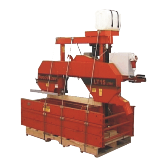
Safety & General Information Components 1.13 Components See Figure 1-3. The major components of the Wood-Mizer LT15 are shown below. Water Tank Sawmill Mast Up/Down Drive Assembly Saw Head Electric Box Blade Tension Handle Blade Drive Motor Blade Guide Operator Box... -
Page 22: Sawmill Assembly
SAWMILL ASSEMBLY Mounting Parts of LT15 Sawmills with Electric Motors SECTION 2 SAWMILL ASSEMBLY Mounting Parts of LT15 Sawmills with Electric Motors 2.1.1 Parts Specifications Table 1: Fig. Wood-Mi Descripti Qty. Qty. Qty. Qty. Qty. Qty. LT15 LT15 LT15 LT15 LT15 LT15 Part No. - Page 23 SAWMILL ASSEMBLY Parts Specifications Table 1: 086172-1 Bottom Bracket 086322 Right Track Wiper 086323 Left Track Wiper 086659-1 Frame Mounting Strap, Zinc-plated 086745 Middle Track Cover with Felt Wiper 092378-1 Bracket, Blade Guide Roller Guard 092379-1 Blade Guide Roller Guard 093859 Plate, PC Guard...
- Page 24 SAWMILL ASSEMBLY Parts Specifications Table 1: 502726-1 Feed Rope Mount Rear Bracket 506287-1 PLATE, LT15 BED SECTION CONNECT 507565 Log Clamp 508236-1 Feed Rope Mount Front Bracket (LT15-EC) 508237-1 Feed Rope Mount Rear Bracket (LT15-EC) 094427-1 Track Rail (LT15S3) 094696-1 (LT15M2) LTBGAT Tool, Blade,...
- Page 25 SAWMILL ASSEMBLY Parts Specifications Table 1: F81043-2 Cotter Pin S-Zn 4x25 F81058-1 Flat Washer Manaual Feed Assembly 506427-1 Power Feed Crank Handle 094142 Bushing 086338 Crank Handle Grip F81033-1 Hex Nylon Lock Nut Power Feed Assembly R80663 Rope 500839 Track Cover w/Felt Wiper...
- Page 26 Bushing, Rubber 091614 Clamp, Rope Outrigger Leg Kit (Option) 095745-1 Mounting Block 087771-1 LT15 Foot Mount Plate 2.1.2 Specifications of Fasteners Table 2: Wood-Mizer No. Description Qty. Qty. Qty. Qty. Qty. Qty. LT15 LT15 LT15 LT15 LT15 LT15 LT15 LT15...
- Page 27 SAWMILL ASSEMBLY Specifications of Fasteners Table 2: 100076-1 M10-20 Special Bolt F81000-7 M5x25 Bolt F81001-15 M6x16-8.8 Bolt F81001-7 M6x12 Bolt F81002-20 M8x16 Bolt F81002-4 M8x20 Bolt F81002-5 M8x25 Bolt F81002-6 M8x12 Bolt F81003-1 M10x20 Bolt F81003-11 Bolt M10x25-8.8 F81003-15 M10x75 Bolt F81003-2 M10x30 Bolt-5.8 F81003-2...
-
Page 28: Unpacking The Sawmill
SAWMILL ASSEMBLY Tools Necessary for Assembling the Sawmill Table 2: F81037-1 M20 Nut F81059-2 21 Flat Washer 2.1.3 Tools Necessary for Assembling the Sawmill Table 3: Required Tools Flat Wrench #8 1pcs Flat Wrench #10 2pcs Flat Wrench #13 2pcs Flat Wrench #17 2pcs Flat Wrench #19... -
Page 29: Bed Frame Assembly
SAWMILL ASSEMBLY Bed Frame Assembly 3. Using a forklift truck or a winch with lifting capacity of minimum 500 kg, carefully lift the saw head and set it aside. Then attach the winch hook to the bracket on the saw head. When removing the saw head, use extreme care and keep all WARNING! persons at a safe distance. - Page 30 SAWMILL ASSEMBLY Bed Frame Assembly See Figure 2-2. 094427-1 (LT15S3) 094696-1 (LT15M2) M10 Hex Nylon Lock Nut 10.5 Washer 150158b M10x75 Bolt FIG. 2-2 2. In case of stationary sawmills - Mount four (or six) legs to each bed section. Use two hex head bolts and lock nuts to secure each leg to the bed section.
- Page 31 SAWMILL ASSEMBLY Bed Frame Assembly See Figure 2-3. M10x75 Bolt 150185B 085994-1 10.5 Washer M10 Hex Nylon Lock Nut 100064-1 FIG. 2-3 3. In case of mobile sawmills - Mount four (or six) leg brackets to each bed section. Use two hex head bolts and lock nuts to secure each leg bracket to the bed section.
- Page 32 SAWMILL ASSEMBLY Bed Frame Assembly See Figure 2-4. M10x120 Bolt 095742-1 085994-1 M20 Nut 150160a 21 Washer 095745-1 M10 Hex Nylon 10.5 Washer Lock Nut 086723-1 FIG. 2-4 4. Lay the frame sections end-to-end so the track portion of each section is on the same side. Slide the sections together and secure with four hex head bolts and nylon lock nuts.
- Page 33 SAWMILL ASSEMBLY Bed Frame Assembly See Figure 2-5. M6x16 M10x30 Bolt (4pcs) M10 Hex Nylon Lock 10.5 Flat Washer 10.2 Split Lock Washer M10x25 Bolt Frame Mounting Strap (086660) 150159D M12x120 Bolt (4pcs) 13 Flat Washer M12 Hex Nylon Lock FIG.
- Page 34 SAWMILL ASSEMBLY Bed Frame Assembly 6. Mount a bed extension to the front and the rear ends of the bed frame. See Figure 2-6. 10.2 Split Lock M12 Hex Nylon Washer Lock Nut M10x75 Bolt 086659-1 10.5 Washer 094250-1 M10x30 13 Flat Bolt M12x120...
-
Page 35: Frame Leg Adjustment
SAWMILL ASSEMBLY Frame Leg Adjustment See Figure 2-7. 150157b 100076-1 Bolt M12 Nut 085981-1 13 Washer 014972 097224 M12x140 Bolt FIG. 2-7 Frame Leg Adjustment 1. Place a foot plate under each bed leg. 2. Using an appropriate wrench, adjust each leg so that the nut is approximately 25mm below the top of the bed tube SAWMILL ASSEMBLY 15doc121912... -
Page 36: Saw Head Assembly
SAWMILL ASSEMBLY Saw Head Assembly See Figure 2-8. (1") 25mm 150108b Foot Plate FIG. 2-8 The top of the leg should not be higher than the top surface of CAUTION! the bed rail. Saw Head Assembly 1. Position the saw head at the end of the bed frame assembly. Carefully slide the saw head rollers onto the bed frame track. - Page 37 SAWMILL ASSEMBLY Saw Head Assembly See Figure 2-9. Track Scraper 8.4 Flat Washer (4) M8 X 12 Hex M8 X 12 Hex Head Bolt (2) Head Bolt (4) 8.4 Flat Washer (4) 150109d Retaining Bracket M8 X 12 Hex Head Bolt (2) Track Scraper FIG.
- Page 38 SAWMILL ASSEMBLY Saw Head Assembly See Figure 2-10. Spring 087301 086743-1 Cotter Pin Washer F81043-2 F81058-1 FIG. 2-10 7. Install the PC operator guard. See Figure 2-11. M8x16 Bolt 8.4 Washer M10x50 Bolt 10.5 Washer FIG. 2-11 8. Install the blade guides. 2-17 15doc121912 SAWMILL ASSEMBLY...
- Page 39 SAWMILL ASSEMBLY Saw Head Assembly See Figure 2-12. Blade Guide 094682 Blade Guide 094683 M10x1x25 Bolt M10x1 Washer M10x1x20 Screw (7) FIG. 2-12 9. Unbolt the control box mounting bolts in travel position. Adjust the control box in operation position and use the mounting bolts to mount it.
- Page 40 SAWMILL ASSEMBLY Saw Head Assembly See Figure 2-13. 150199 Control box in travel position 150200 Control box in operation position FIG.. 2-13 2-19 15doc121912 SAWMILL ASSEMBLY...
- Page 41 SAWMILL ASSEMBLY Saw Head Assembly 10. Turn the power feed motor (if equipped) from the travel position to the work position. The motor should be positioned as shown in the figure below. Tighten the motor mounting screws 150236 Motor Mounting Screws FIG..
- Page 42 SAWMILL ASSEMBLY Saw Head Assembly See Figure 2-14. Power Cord Bracket 086132-1 150163c FIG. 2-14 12. Adjust the cam engaging the limit switch as well as the saw head stop bolt. See Section , step 3-8. 2-21 15doc121912 SAWMILL ASSEMBLY...
-
Page 43: Manual Feed Rope Assembly
SAWMILL ASSEMBLY Manual Feed Rope Assembly Manual Feed Rope Assembly 1. Install a feed rope mounting bracket at each end of the bed assembly using a M10x30 hex head bolts and washers. Either bracket should be angled toward the end of the frame at which it is mounted as shown below. - Page 44 SAWMILL ASSEMBLY Manual Feed Rope Assembly 3. Loop the rope around the inner groove of the lower v-groove roller and route to the feed crank spool. See Figure 2-17. 150111 FIG. 2-17 4. Loop the rope around the feed crank spool three times and route back down to the outer v-groove roller. See Figure 2-18.
- Page 45 SAWMILL ASSEMBLY Manual Feed Rope Assembly See Figure 2-19. 150113 FIG. 2-19 6. Route the rope to the rear mounting bracket. Tie a knot in the end of the rope and insert into the mounting bracket. Position the knot in the rope so when installed to the rear bracket, the rope is tight. 150011B FIG.
-
Page 46: Power Feed Rope Assembly
SAWMILL ASSEMBLY Power Feed Rope Assembly Power Feed Rope Assembly 1. Before installation of the rope, make sure the power feed motor is properly positioned in relation to the gear box, as shown in the figure below. If not, turn the motor until it is in the operation position. Secure the motor to the gear box with the mounting screws. - Page 47 SAWMILL ASSEMBLY Power Feed Rope Assembly 3. Prepare the rope for installation by placing steel caps on its ends. 4. Install the rope, route it around the pulley, as shown below, and secure with clamps (1). Power Feed Motor In Operation Position SAWMILL ASSEMBLY 15doc121912...
- Page 48 SAWMILL ASSEMBLY Power Feed Rope Assembly 5. Adjust the rope tension so that gaps between the spring coils are .8-1.2 mm. (0.031-0.047") 0,8-1,2mm 2-27 15doc121912 SAWMILL ASSEMBLY...
-
Page 49: Auxiliary Bed Rail
SAWMILL ASSEMBLY Auxiliary Bed Rail Auxiliary Bed Rail To install the auxiliary bed rail to a bed frame section, use the set of mounting holes provided between the two bed rails. Remove the existing bolt and lock nut that secures the track at this position. Use three hex head bolts and lock nuts to secure the bed rail to the bed section. -
Page 50: Log Loading Ramp (Option)
SAWMILL ASSEMBLY Log Loading Ramp (Option) Log Loading Ramp (Option) To install the log loading ramp, mount the ramp bracket (1) to the bed frame section tube using two bolts (2), four washers (3) and two nuts (4) in the place shown below. Insert the ramp assembly (5) into the ramp bracket. -
Page 51: Section 3 Setup & Operation
Setup & Operation Sawmill Setup SECTION 3 SETUP & OPERATION Sawmill Setup Before starting to use the sawmill you have to meet the IMPORTANT! following conditions: Set up the sawmill on firm, level ground and level the sawmill. Secure the sawmill to the ground to ... - Page 52 Setup & Operation Sawmill Setup Assemblies aligned at the factory: Blade drive belt tension; Engine r.p.m. (DC only); Blade wheels (in vertical and horizontal planes); Blade guide arm alignment - See Section 6.5; Blade guides - ...
- Page 53 Setup & Operation Sawmill Setup See Figure 3-1. Equal height Equal height object object Measure distance Measure distance between string between string and bed rails and bed rails 150115c Equal height Equal height String Across object String across object bed rails bed rails FIG.
- Page 54 Setup & Operation Sawmill Setup Use the saw head adjustment nuts to move the outside of the saw head up or down. Lock Nut Saw Head Adjustment Nuts (2) 150116D Roller Bracket Mast Retaining Mounting Bolt (4) Bracket Mounting Bolts (2) Scraper Mounting Bolts (2) FIG.
- Page 55 Setup & Operation Sawmill Setup 10. Check the vertical alignment of each blade wheel using the blade guide alignment tool. Attach the tool to the blade near the outer blade guide. Be sure the tool does not rest on a tooth or ...
- Page 56 Setup & Operation Sawmill Setup To tilt wheel up, tighten top screw (loosening ealier bottom screw). To tilt wheel down, tighten bottom screw (loosening ealier top screw). FIG. 3-4 See Figure 3-5. To tilt the drive-side blade wheel down, loosen the top adjustment screw, loosen the nut on the bottom adjustment screw and tighten the bottom screw.
- Page 57 Setup & Operation Sawmill Setup To tilt wheel up, tighten top screw (loosening ealier bottom screw). To tilt wheel down, tighten bottom screw (loosening ealier top screw). Alignment 150075-1G Tool FIG. 3-5 Recheck the vertical alignment of each blade wheel. Readjust if necessary. ...
- Page 58 Setup & Operation Sawmill Setup 15. Bolt the blade guide guard so that its bottom edge is about 5 mm above the blade. FIG. 3-5 16. Adjust the cam engaging the limit switch as well as the saw head stop bolt so that the saw head stops 15doc121912 Setup &...
-
Page 59: Replacing The Blade
Setup & Operation Replacing The Blade moving at its lower travel limit, i.e. at the height of 25 mm above the bed. Loosen the nut and adjust the stop bolt Loosen bolts and adjust cam engaging limit switch Limit Switch FIG. -
Page 60: Tensioning The Blade
Setup & Operation Tensioning The Blade Install a new blade on the blade wheels. When installing the blade, make sure the teeth are pointing the correct direction. The teeth located between the blade guide assemblies should be pointing toward the sawdust chute. -
Page 61: Tracking The Blade
Setup & Operation Tracking The Blade Tracking The Blade 1. Make sure the blade housing cover is closed and all persons are clear of the blade. 2. Start the motor for a moment until the blade positions itself on the wheels. Do not spin the blade wheels by hand. -
Page 62: Starting The Motor
Setup & Operation Starting The Motor If the blade is too far out, back the blade onto the wheel by turning the cant control counterclockwise. If the blade is too far in, turn the cant control clockwise until the gullet of the blade is the correct distance from the front edge of the wheel. -
Page 63: Loading, Turning, And Clamping Logs
Setup & Operation Loading, Turning, And Clamping Logs Loading, Turning, And Clamping Logs To Load Logs 1. Move the cutting head to the front end of the frame. Before loading a log, be sure the cutting head is moved far CAUTION! enough forward so the log does not hit it. - Page 64 Setup & Operation Loading, Turning, And Clamping Logs See Figure 3-9. 150117D FIG. 3-9 2. Make sure the side supports are positioned low enough for the blade to pass over them. If they are not, back the clamps off slightly and push the side supports down until they are positioned below the height of your last cut on a given side of the log.
-
Page 65: Up/Down Operation
Setup & Operation Up/Down Operation of the log. Level log so Leveling heart is same Wedge distance from bed rails at both ends 150119C FIG. 3-9 Up/Down Operation 1. Install a blade, if needed, and check for correct blade tension. (See Section 3.3.) Set the cutting head to the desired height. -
Page 66: Blade Guide Arm Operation
Setup & Operation Blade Guide Arm Operation See Figure 3-10. Use the up and down buttons shown below to raise or lower the cutting head. To raise the saw head press up button. To lower the saw head press down button. FIG. -
Page 67: Blade Drive Operation
Setup & Operation Blade Drive Operation See Figure 3-11. 150120 Move the handle right to move Move the handle right the blade arm out. to move the blade arm out. Move it left to move the blade Move it left to move guide in. -
Page 68: Feed Operation
Setup & Operation Feed Operation - Press the START button on the control box to start the motor. Main Electrical Switch Motor Start Button Power ON Debarker Control Light Switch (option) Debarker Safety In/Out Button Feed Rate Adjustment Power Feed Joystick Up/Down Emergency... - Page 69 Setup & Operation Feed Operation See Figure 3-2. Turn the crank clockwise for forward feed; counterclockwise to return the saw head 150122C FIG. 3-2 HINT: To get a straight cut in the first part of the board, feed the blade into the log at a slow speed. This stops the blade from flexing and dipping up or down.
- Page 70 Setup & Operation Feed Operation See Figure 3-3. Saw Head Forward Feed Rate Adjustment Saw Head Reverse FIG. 3-3 Saw Head Feed Rate The saw head feed rate switch controls the speed at which the saw head travels forward. Turn the switch clockwise to increase speed.
-
Page 71: Cutting The Log
3.11 Cutting The Log The following steps guide you through normal operation of the Wood-Mizer sawmill. 1. Once the log is placed where you want it and clamped firmly, position the blade close to the end of the log. -
Page 72: Edging
Edging 3.12 Edging The following steps guide you through edging boards on the Wood-Mizer sawmill. 1. Raise the side supports to 1/2 the height of the flitches, or the boards that need to be edged. 2. Stack the flitches on edge against the side supports. - Page 73 Setup & Operation Blade Height Scale The Scale The horizontal red line on the blade height indicator shows how many centimeters the bottom of the blade is above the bed of the mill. If you know the height of your blade at each cut, you can determine the thickness of lumber you are sawing.
-
Page 74: Water Lube Operation
Setup & Operation Water Lube Operation 3.14 Water Lube Operation The Water Lube System keeps the blade clean. Water flows from a 5-gallon (18.9 liter) bottle through a hose to the blade guide where the blade enters the log. A valve in the bottle cap controls the amount of water flow. See Figure 3-5. - Page 75 Setup & Operation Water Lube Operation See Figure 3-6. Route the water hose as shown below. Secure it with the provided hose clamps at the locations marked with red points in the figure. 150155B Connect water hose to blade guide FIG.
- Page 76 Setup & Operation Water Lube Operation See Figure 3-7. Open the valve on the water bottle to start the water flow. A stream of water flows to the blade only when the main motor is turned on. Turn valve counterclockwise Turn valve counterclockwise to open;...
-
Page 77: Transporting The Sawmill
Setup & Operation Transporting the Sawmill 3.15 Transporting the Sawmill The assembled sawmill can be transported in an appropriately equipped pickup truck: 1. Adjust the cutting head up just far enough so it will clear the sides of your truck bed when loaded. Do not adjust the cutting head so high that the sawmill will tip easily while being loaded. - Page 78 Wood-Mizer LT15 Short Interval Maintenance Schedule (Check engine and option manuals for additional maintenance procedures) PROCEDURE MANUAL REFERENCE EVERY BLADE CHANGE Check Blade Guide Roller Performance SEE SECTION 4.2 Remove Excess Sawdust From Blade Wheel Housings And Sawdust Chute SEE SECTION 4.2...
- Page 79 WOOD-MIZER LT15 MAINTENANCE LOG (Check Engine And Option Manuals For Additional Maintenance Procedures) PROCEDURE MANUAL TOTAL HOURS OF OPERATION REFERENCE FILL IN THE DATE AND THE MACHINE HOURS AS YOU PERFORM EACH PROCEDURE. A SHADED BOX INDICATES MAINTENANCE IS NOT NEEDED AT THIS TIME.
- Page 80 WOOD-MIZER LT15 MAINTENANCE LOG (Check Engine And Option Manuals For Additional Maintenance Procedures) PROCEDURE MANUAL TOTAL HOURS OF OPERATION REFERENCE FILL IN THE DATE AND THE MACHINE HOURS AS YOU PERFORM EACH PROCEDURE. A SHADED BOX INDICATES MAINTENANCE IS NOT NEEDED AT THIS TIME.
- Page 81 WOOD-MIZER LT15 MAINTENANCE LOG (Check Engine And Option Manuals For Additional Maintenance Procedures) PROCEDURE MANUAL TOTAL HOURS OF OPERATION REFERENCE FILL IN THE DATE AND THE MACHINE HOURS AS YOU PERFORM EACH PROCEDURE. A SHADED BOX INDICATES MAINTENANCE IS NOT NEEDED AT THIS TIME.
-
Page 82: Section 4 Maintenance
Maintenance Wear Life SECTION 4 MAINTENANCE This section lists the maintenance procedures that need to be performed. The Short Interval Maintenance Schedule lists procedures that need to be performed every 4, 8 or 25 hours.The Maintenance Log lists procedures that need to be performed every 50, 100, 200, or 1000 hours. Keep track of machine maintenance by filling in the machine hours and the date you perform each procedure. -
Page 83: Vertical Mast Rails
Maintenance Vertical Mast Rails sawdust buildup from the housings. Middle Track Cover Middle Track Cover Track Roller Track Roller Housing Housing Track Roller Housing Track Roller Housing Idle Track Wipers Idle Track Wipers 15B030B FIG. 4-2 Vertical Mast Rails Clean and lubricate the vertical mast rails every 50 hours of operation. Clean with solvent and remove any rust with a light-grade sand paper. -
Page 84: Blade Wheel Belts
Maintenance Blade Wheel Belts See Figure 4-3. Grease Tensioner Threads FIG. 4-4 Blade Wheel Belts 1. Rotate the blade wheel belts and check them for wear. Rotating the belts every 50 hours will give you longer belt life. Replace belts as necessary. Use only B57 belts manufactured by Goodyear or Browning. 2. - Page 85 Maintenance Up/Down System See Figure 4-5. Upper Limit Switch Up/Down Screw Bellows Lower Bearing Housing Lower Limit 150126B Switch FIG. 4-6 2. Lubricate the up/down acme screw with a rolling bearing lubricant (e.g. ŁT4S or Shell Extreme Pressure Grease) every six months. Apply the lubricant to the grease fitting in the nut housing. Lubrication may be required sooner if environmental conditions require it.
- Page 86 Maintenance Up/Down System Unbolt the up/down top guard. Loosen the motor mounting bolts. Use the adjustment bolt See Figure 4-7. the top guard. shown below to adjust the belt tension. Tighten the motor mounting bolts. Replace Force=25 Adjustment Bolt Deflection= Motor Mounting Bolts FIG.
- Page 87 Maintenance Up/Down System 4. Every 200 hours of operation check and adjust if necessary the up/down motor brake air gap. FIG. 4-9 Electromagnet body Coil Armature Brake disk Gear wheel Mounting disk Spring Thrust pin 10. Mounting bolt 11. Adjusting bolt 12.
-
Page 88: Miscellaneous Maintenance
Maintenance Miscellaneous Maintenance AIR GAP ADJUSTMENT The air gap ,,a" grows gradually larger in consequence of wear of brake disc lining (5). The niminal value of the air gap a nom " may be restored by screwing in the adjusting bolts (11). Prior to adjustment, slacken mounting bolts (10) and then set the nominal value of air gap using the feeler gauge inserted between armature (4) and body and screwing in the adjusting bolts (11). -
Page 89: Safety Devices Inspection
Maintenance Safety Devices Inspection Safety Devices Inspection LT15 AC – Safety Devices Inspection Safety devices on the LT15AC machine which must be checked before every shift: E-STOP button and its circuit inspection Green safety button inspection Inspection of the control circuits with the E-STOP button pressed ... - Page 90 Maintenance Safety Devices Inspection 2. Green safety button inspection Be sure the E-STOP button is released; Press and hold the green safety button; Turn on the blade motor. The motor should be started; Release the safety button. The blade motor should be stopped. ...
-
Page 91: Section 5 Troubleshooting Guide
Troubleshooting Guide Sawing Problems SECTION 5 TROUBLESHOOTING GUIDE Sawing Problems PROBLEM CAUSE SOLUTION Dirty logs Clean or debark logs, especially on Blades Dull Quickly entry side of the cut When grinding teeth, heating too much Grind just enough metal to restore and causing teeth to soften sharpness to the teeth. - Page 92 Troubleshooting Guide Sawing Problems PROBLEM CAUSE SOLUTION Stress in log which causes log to not lay After log has been squared, take equal Boards Thick Or Thin On flat on the bed cuts off opposing sides. Take a board Ends Or Middle Of Board off the top.
-
Page 93: Section 6 Alignment
Alignment Pre-Alignment Procedures SECTION 6 ALIGNMENT Pre-Alignment Procedures Periodically check the sawmill alignment and adjust if necessary. This chapter explains how to align the entire sawmill. Care should be taken in performing these steps. Sawmill alignment determines the accuracy and squareness of your cuts. The sawmill alignment steps are: 1. -
Page 94: Blade Wheel Alignment
Alignment Blade Wheel Alignment 150060 3.0 mm (0.12”) ± 1 mm (0.04”) 1 1/4" Blade Blade FIG. 6-1 To adjust where the blade travels on the idle-side and drive-side blade wheel, See Section 6.4. Blade Wheel Alignment The blade wheels should be adjusted so they are level in the vertical and horizontal planes. If the blade wheels are tilted up or down, the blade will want to travel in the tilted direction. - Page 95 Alignment Blade Wheel Alignment wheel. See Figure 6-3. Use the vertical adjustment screws to adjust the drive-side blade wheel. To tilt the wheel, loosen the top adjustment screw one quarter turn. Loosen the jam nut on the bottom adjustment screw and tighten the screw.
- Page 96 Alignment Blade Wheel Alignment Adjust vertical adjustment screws up to tilt idle-side blade wheel down; Adjust screws down to tilt wheel up FIG. 6-4 8. Recheck the vertical tilt of the idle-side blade wheel with the blade guide alignment tool. Readjust the blade wheel as necessary until the front and rear of the tool are the same distance from the bed rail (within 1/16"...
- Page 97 Alignment Blade Wheel Alignment 150060 3.0 mm (0.12”) ± 1 mm (0.04”) 1 1/4" Blade Blade FIG. 6-5 See Figure 6-6. Use the cant control adjustment to adjust the idle-side blade wheel. If the blade is too far forward on the wheel, turn the cant control counterclockwise. If it is too far back on the wheel, turn the cant control clockwise.
-
Page 98: Blade Guide Arm Alignment
Alignment Blade Guide Arm Alignment screw to move blade in on wheel. Tighten the jam nut. Spring Bolt Adjustment Screw 150127B FIG. 6-7 It is not necessary to align the spring bolt (bolt M10x75 [WM# F81003-15] + spring + washer) shown NOTE: in the figure above. - Page 99 Alignment Blade Guide Arm Alignment See Figure 6-8. Adjust front top and bottom Adjust rear top and bottom screws with arm open screws with arm closed FIG. 6-8 2. Use the arm adjustment screws, marked with blue arrows in the figure above, to adjust the arm up until the slide pad touches the saw head brace tube.
-
Page 100: Aligning The Blade Guides
Aligning The Blade Guides Each Wood-Mizer sawmill has two blade guide assemblies that help the blade maintain a straight cut. The two blade guide assemblies are positioned on the saw head to guide the blade on each side of the material being cut. -
Page 101: Blade Guide Vertical Tilt Adjustment
Alignment Blade Guide Vertical Tilt Adjustment See Figure 6-10. Turn jam nuts to adjust Turn jam nuts to adjust roller up or down roller up or down SM0068 FIG. 6-10 2. Loosen the bottom jam nut and tighten the top jam nut until the blade guide deflects the blade down 1/4" (6 mm). -
Page 102: Blade Guide Spacing
Alignment Blade Guide Spacing 5. Measure the distance from the bed rail to the bottom edge of the tool. 6. Loosen one set screw at the side of the blade guide assembly. 7. Use the set screws shown to tilt the blade guide until the measurement from the bed rail to the tool equals the first measurement taken at the center of the tool. -
Page 103: Horizontal Tilt Adjustment
Alignment Horizontal Tilt Adjustment See Figure 6-13. Loosen one top and one side set screw 1,5 - 3,0 mm Adjust distance between roller and back of blade SM0071a FIG. 6-13 3. Retighten the two set screws. 4. Adjust the outer blade guide in the same way so the blade guide flange is approximately 1/16" - 1/8" (1.5 - 3.0 mm) from the back of the blade. -
Page 104: Side Supports
Alignment Side Supports closest to the inner blade guide ("B"). 4. Measure between the back edge of the blade and the other end of the ruler ("A"). 5. The roller should be parallel to the blade (A=B) or tilted slightly to the left (A=B-1/4" [6 mm]). 6. -
Page 105: Blade Height Scale Adjustment
Alignment Blade Height Scale Adjustment 6.12 Blade Height Scale Adjustment After the entire sawmill has been aligned and all adjustments made, check that the blade height scale indicates the true distance from the blade to the bed rails. 1. The maximum distance between the scale and the scale indicator should be 5 mm. If it is different, loosen the indicator bracket mounting bolts and move the bracket in the horizontal plane until the correct distance is obtained. -
Page 106: Motor Drive Belt Adjustment
Alignment Motor Drive Belt Adjustment 6.13 Motor Drive Belt Adjustment See Figure 6-16. Loosen the motor mounting bolts. Using the adjustment bolts shown below, adjust the drive belt until it has 7/16" (11 mm) deflection with a 8 lbs (3.6 kG) deflection force - in the case of E11 motor or 7/16"... -
Page 107: Track Roller Distance Adjustment
Alignment Track Roller Distance Adjustment 6.14 Track Roller Distance Adjustment Using the screw (1), adjust the distance between the track roller (2) and the track rail (3) so that the mast can move freely (see the figure below). The distance should be about 0.5 mm. FIG. - Page 108 EC declaration of conformity according to EC Machinery Directive 2006/42/EC We herewith declare, Wood-Mizer Industries sp. Z O.O. 114 Nagorna street, 62-600 Kolo; Poland. That the following described machine in our delivered version complies with the appropriate basic safety and health requirements of the EC Machinery Directive 2006/42/EC based on its design and type, as brought into circulation by us.
Need help?
Do you have a question about the LT15 S2-4 E11S and is the answer not in the manual?
Questions and answers