Table of Contents
Advertisement
Quick Links
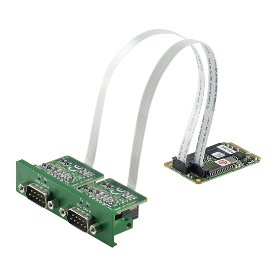
PCM-26D2CA
2-Ports Isolated CANBus mPCIe, CANOpen, DB9
Startup Manual
Packing List
Before installation, please ensure that the following items
have been included in your shipment:
1. mPCIe card with CAN controller x 1
2. DB9 I/O plate x 2 with iDoor bracket x 1
3. FPC cable x 2
4. Startup manual x 1
5. Warranty card x 1
If any of the above items are missing or damaged, contact
your distributor or sales representative immediately.
For more information on this and other Advantech
products, please visit our website at:
http://www.advantech.com
http://www.advantech.com/eAutomation
For technical support services, please visit our support
website at:
http://www.advantech.com.tw/eservice
This manual is for the PCM-26D2CA-BE.
Part No. 204426D201
Edition 2
December 2022
PIN Assignment
The following tables and figures show the pin assignments
of the connector on the bracket to the modular card. If you
see two ports or above, it will use the same pin-definition
as this one.
PIN
1
2
3
4
5
6
7
8
9
Installation
PCM module with iDoor technology supports the following
Advantech platforms:
Automation computers - UNO series
Panel PC - TPC series
Modular IPC - MIC series
See the following page for installation in TPC embedded panel
computers and UNO embedded computers.
PCM-26D2CA Startup Manual 1
CAN Port
-
CAN_L
GND
-
-
-
CAN_H
-
-
Advertisement
Table of Contents

Related Manuals for Advantech PCM-26D2CA


Summary of Contents for Advantech PCM-26D2CA
- Page 1 PCM module with iDoor technology supports the following Advantech platforms: Automation computers - UNO series For more information on this and other Advantech products, please visit our website at: Panel PC - TPC series Modular IPC - MIC series http://www.advantech.com...
- Page 2 Status Resistor PIN 1-2 (Default) Closed Mode 120 Ohms PIN 2-3 Open Mode The support documentation can be accessed from https:// www.advantech.com/support. 4. Secure the PCM Module with the screws you removed from the blanking plate. 2 PCM-26D2CA Startup Manual...
- Page 3 2. Insert the mini-PCI card and secure with the screws. FPC Cable Installation Please follow the direction as shown in the picture. The corresponded port was marked A/B on motherboard for cable plug-in direction. 3. Remove the screws to remove the blanking plate. PCM-26D2CA Startup Manual 3...
Need help?
Do you have a question about the PCM-26D2CA and is the answer not in the manual?
Questions and answers