
Related Manuals for Advantech PCI-1241


Summary of Contents for Advantech PCI-1241
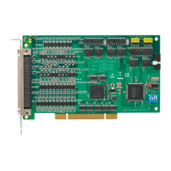
- Page 1 PCI-1241 4-Axis Voltage-type Servo Motor Control Card PCI-1242 4-Axis Pulse-type Servo motor Control Card User Manual...
- Page 2 No part of this man- ual may be reproduced, copied, translated or transmitted in any form or by any means without the prior written permission of Advantech Co., Ltd. Information provided in this manual is intended to be accurate and reli- able.
- Page 3 2 Year Product Warranty Advantech warrants to you, the original purchaser, that each of its prod- ucts will be free from defects in materials and workmanship for two years from the date of purchase. This warranty does not apply to any products which have been repaired or...
- Page 4 CE test for environmental specifications when shielded cables are used for external wiring. We recommend the use of shielded cables. This kind of cable is available from Advantech. Please contact your local sup- plier for ordering information. FCC Class A This equipment has been tested and found to comply with the limits for a Class A digital device, pursuant to Part 15 of the FCC Rules.
-
Page 5: Packing List
• Driver CD-ROM (DLL driver and Utility included) • 10-pin horn female connector to DB-9 male connectors conversion bracket • PCI-1242: One bracket with two DB-9 connectors • PCI-1241: One bracket with two DB-9 connectors and one bracket with one DB-9 connector... - Page 6 PCI-1241/1242 User Manual...
-
Page 7: Table Of Contents
Software 8 Hardware Installation ............9 2.2.1 Board Layout and Jumper/Switch Settings ....10 Figure 2.2:Location of Jumpers and VRs on PCI-1241/42 Table 2.1:Summary of Jumper and Connector Settings .. Chapter 3 Signal Connections ........14 I/O Connector Pin Assignments........14 Figure 3.1:J1 Remote I/O Connector Pin Assignments 14... - Page 8 Figure 3.14:MPG Encoder Input Wiring Diagram ..35 3.6.2 Remote I/O Connection ..........36 Figure 3.15:Remote I/O DB-9 Connector Pin Assignment Figure 3.16:Remote I/O Wiring Diagram in PCI-1241 36 Figure 3.17:Remote I/O Wiring Diagram in PCI-1242 37 3.6.3 Field Wiring Considerations ........38 Chapter 4 Configuration Utility........
- Page 9 Other Motion Functions: ..........69 General: ................69 Appendix B Block Diagram ..........72 Appendix B. Block Diagram........72 Figure B.1:PCI-1241/1242 System Block Diagram ..72 Open Loop Motion Control (Pulse Command)....73 B.2.1 Digital Differential Analyzer (DDA) ......73 Figure B.2:DDA Example ...........
- Page 10 Figure C.13:Velocity Profile of Home Mode12 ..90 C.15 Home mode13 ..............90 Figure C.14:Velocity Profile of Home Mode13 ..90 Appendix D Remote I/O ............. 92 Features ................92 Specifications ..............93 Figure D.1: ..............93 Figure D.2: ..............93 PCI-1241/1242 User Manual...
-
Page 11: General Information
General Information This chapter provides general informa- tion on the PCI-1241/42. Sections include: • Introduction • Features • Applications • How to get Started • Software Programming Choices • Accessories... -
Page 12: Chapter 1 Introduction
Chapter 1 Introduction 1.1 Introduction PCI-1242 is a 4-Axis Pulse-type Motion Control Card and PCI-1241 is a 4-axis Pulse/Voltage-command Motion Control Card. In pulse output control, these motion control cards use a synchronous DDA (Digital Dif- ferential Analyzer) pulse generator to send out pulses evenly and simulta- neously, which successfully realizes synchronous four-axis positioning and motion control. -
Page 13: Features
PCI-1241/1242 provides the motor control functions as seen below: • Independent 4-axis motion control • Each axis of PCI-1241 can be configured independently as closed loop control (voltage command) or open loop control (pulse command). • 2/3-axis linear interpolation function •... -
Page 14: Applications
• Semiconductor pick and place and testing equipment • Other stepping motor and pulse/velocity-type servo motor applications 1.4 How to Get Started Before you install your PCI-1241/1242 card, please make sure you have the following necessary components: • PCI-1241 or PCI-1242 motor control card •... -
Page 15: Figure 1.1:Installation Flow Chart
Install Driver from CD-ROM, then power off PC Install Hardware and power on PC Use PCI-1241_42_61 Utility to configure hardware Use PCI-1241_42_61 Utility to test hardware Read Examples & Hardware/Software manual Start to write your own application Figure 1.1: Installation Flow Chart Chapter 1... -
Page 16: Software Programming Choices
(Included in the companion CD-ROM) • Motion Utility: Advantech PCI-1241_42_61 Utility (Included in the companion CD-ROM) 1.6 Accessories Advantech offers a complete set of accessory products to support the PCI- 1241/1242 cards. These accessories include: 1.6.1 Wiring Cables • PCL-10168 The PCL-10168 shielded cable is specially designed for PCI-1241/ 1242 motion control cards to provide high resistance to noise. - Page 17 Installation This chapter provides information on the installation of PCI-1241/42. Sections include: • Software Installation • Hardware Installation...
-
Page 18: Chapter 2 Installation
Chapter 2 Installation 2.1 Software Installation We recommend you to install the driver before you install the PCI-1241/ 42 card into your system, since this will guarantee a smooth installation process. The 32-bit DLL driver Setup program for the card is included on the com- panion CD-ROM that is shipped with your DAS card package. -
Page 19: Hardware Installation
Step 4: Touch the metal part on the surface of your computer to neutral- ize the static electricity that might be on your body. Step 5: Insert the PCI-1241/42 card into a PCI slot. Hold the card only by its edges and carefully align it with the slot. Insert the card firmly into place. -
Page 20: Board Layout And Jumper/Switch Settings
2.2.1 Board Layout and Jumper/Switch Settings Figure 2.2 shows the names and locations of jumpers and VRs on the PCI-1241/1242. There are 5 jumpers and 4 VRs on PCI-1241/1242. Table 2-1 shows jumpers and VRs functionalities.. Figure 2.2: Location of Jumpers and VRs on PCI-1241/42... - Page 21 Function Description Remote I/O channel 1 for PCLD-8241, 10-pin simple horn female connector type Remote I/O channel 2 for PCLD-8241, 10-pin simple horn (PCI-1241 female connector type only) Encoder Input channel for Manual Pulse Generator (MPG), 10-pin simple horn female connector type...
- Page 22 Variable resistors to adjust voltage output channels OFFSET (PCI-1241 voltage: only) VR1 is for channel A0_VO OFFSET voltage VR2 is for channel A1_VO OFFSET voltage VR3 is for channel A2_VO OFFSET voltage VR4 is for channel A3_VO OFFSET voltage PCI-1241/1242 User Manual...
- Page 23 Signal Connections This chapter provides useful informa- tion about how to connect input and output signals to the PCI-1241/1242 via the I/O connector. Sections include: • I/O Connector Pin Assignments • Voltage Output Connection • Pulse Output Connection • Local Input Connection •...
-
Page 24: Chapter 3 Signal Connections
There are four I/O connectors on the PCI-1241/1242. J1 is internal on- board 10-pin simple horn connector for remote I/O module PCLD-8241. J2 is also for PCLD-8241 and provided by PCI-1241 only. J3 is also a internal on-board 10-pin simple horn connector to provide encoder input... -
Page 25: Table 3.1:Pci-1241/1242 I/O J1 Conn. Signal Descrip Tion – Remote I/O
Table 3.1: PCI-1241/1242 I/O J1 Conn. Signal Description – Remote I/O Signal Reference Direction Description Name RIO1_CLKP Output RI/O Ch. 1 Clock Output + RIO1_CLKN Output RI/O Ch. 1 Clock Output - RIO1_SCSP Output RI/O Ch. 1 Slave Module Acti-... -
Page 26: Table 3.2:Pci-1241/1242 I/O J2 Conn. Signal Descrip Tion – Remote I/O
Table 3.2: PCI-1241/1242 I/O J2 Conn. Signal Description – Remote I/O Signal Reference Direction Description Name RIO2_CLKP Output RI/O Channel 2 Clock Output + RIO2_CLKN - Output RI/O Channel 2 Clock Output - RIO2_SCSP - Output RI/O Channel 2 Slave Module... -
Page 27: Table 3.3:Pci-1241/1242 I/O J3 Conn. Signal Descrip Tion – Mpg Input
Table 3.3: PCI-1241/1242 I/O J3 Conn. Signal Description – MPG Input Signal Reference Direction Description Name MPG_ECAP Input MPG Encoder Input Phase A MPG_ECAN - Input MPEG Encoder Input Phase MPG_ECBP Input MPG Encoder Input Phase B MPG_ECBN - Input... - Page 28 11 A2_HOME A1_SERVON 10 A0_SERVON A1_LMT- 9 A0_LMT- A1_LMT+ 8 A0_LMT+ A1_HOME 7 A0_HOME P_RDY 6 E_STOP VEX_GND 5 VEX VO_VCC 4 A3_VO A2_VO 3 A1_VO A0_VO 2 GND 1 GND Figure 3.4: SCSI-II 68-pin Connector Pin Assignments PCI-1241/1242 User Manual...
-
Page 29: Table 3.4:Pci-1241/1242 I/O Conn. Signal Desc. – Dda Pulse Output
Table 3.4: PCI-1241/1242 I/O Conn. Signal Desc. – DDA Pulse Output Signal Reference Direction Description Name A0_PAP Output Axis 0 Pulse Output Phase A A0_PAN Output Axis 0 Pulse Output Phase A/ A0_PBP Output Axis 0 Pulse Output Phase B... -
Page 30: Table 3.5:Pci-1241/1242 I/O Conn. Signal Desc. – En Coder Input
Table 3.5: PCI-1241/1242 I/O Conn. Signal Desc. – Encoder Input Signal Reference Direction Description Name A0_ECAP Input Axis 0 Encoder Input Phase A A0_ECAN Input Axis 0 Encoder Input Phase A/ A0_ECBP Input Axis 0 Encoder Input Phase B A0_ECBN... -
Page 31: Table 3.6:Pci-1241/1242 I/O Connector Signal Descrip Tion – Local I/O
Table 3.6: PCI-1241/1242 I/O Connector Signal Description – Local I/O Signal Name Reference Direction Description A0_HOME VEX_GND Input Axis 0 Home Sensor Input A0_LMT+ VEX_GND Input Axis 0 + Direction Limit Input A0_LMT- VEX_GND Input Axis 0 - Direction Limit Input... -
Page 32: Table 3.7:Pci-1241 I/O Conn. Signal Desc. – Voltage Output & Others
Table 3.7: PCI-1241 I/O Conn. Signal Desc. – Voltage Output & Others Pin No. Signal Reference Direction Description Name A0_VO Output Axis 0 Voltage Output A1_VO Output Axis 1 Voltage Output A2_VO Output Axis 2 Voltage Output A3_VO Output Axis 3 Voltage Output... -
Page 33: Voltage Output Connection (Pci-1241 Only)
A3_VO. These four channels are velocity command output for connecting with Vcmd input channels of SERVO MOTOR DRIVER accordingly. Be noted that PCI-1241 ground channel GND must be connected to ground pin of SERVO MOTOR DRIVER. The motor encoder signal of SERVO MOTOR DRIVER (A/B/Z signals) must be connected back to PCI-1241 in DIFFERENTIAL form. -
Page 34: Motor Driver
Figure 3.5: Wiring Diagram between PCI-1241 and Servo Motor Driver PCI-1241/1242 User Manual... -
Page 35: Pulse Output Connection
3.3 Pulse Output Connection PCI-1241/1242 supports 4-axis pulse output channels for pulse-type servo motor driver and stepping motor driver control. Pulse Output Specifications • Differential signal transmission method. Refer to Figure 3-6. A transmitter will convert the input signal X into X and X/ before outputting, and a receiver will compare the X and X/ inputs to obtain Y. -
Page 36: Figure 3.7:Pulse Output Format
P+, P+/, P- and P-/ channels of the pulse-type servo motor driver / stepping motor driver accordingly, as shown in Figure 3- • Be noted that PCI-1241/42 ground channel GND must be connected to the ground pin of the motor driver. -
Page 37: Figure 3.8:Wiring Diagram Between Pci-1241/42 And Pulse-Type Driver
Figure 3.8: Wiring Diagram Between PCI-1241/42 and Pulse-Type Driver 3.4 Local Input Connection PCI-1241/42 provides 13 dedicated input channels. There are four types of local input channels: • 4-channel Positive-direction Limit Switch Inputs – A0_LMT+, A1_LMT+, A2_LMT+, and A3_LMT+. • 4-channel Negative-direction Limit Switch Signal –... - Page 38 RC filter. Emergency Input If an emergency stop occurs (value is 1), pulse outputs will be disabled, voltage output values become 0 V and PCI-1241/42’s built-in LATCH will latch the status of the emergency stop channel. Bouncing State When the mechanical switch in Figure 3-9 is turned from ”Open”...
-
Page 39: Figure 3.9:Local Input Wiring Diagram
• 2500VDC isolation protection Output Type PCI-1241/42 output channels are all open collectors. When the output signal value is “0”, an open collector channel is in “ON” state and the load is activated. When the output signal value is “1”, an open collector channel is in “OFF”... -
Page 40: Figure 3.10:Local Output Wiring Diagram
When the load is a RELAY, it’s not necessary for you to connect an exter- nal diode to absorb pulse noise because there is an instant over voltage protection diode onboard. Figure 3.10: Local Output Wiring Diagram PCI-1241/1242 User Manual... -
Page 41: Local I/O Wiring Example
3.6 Local I/O Wiring Example In this section, it shows a local I/O wiring example of PCI-1241/42 that helps you to setup a system quickly. Figure 3-8 and Figure 3-9 show examples of PCI-1241/42 local I/O wiring diagram of axis one. In the example, all input channels are configured as source type. - Page 42 24 V power sources are used they must have common ground. In addition, the conducting wire should be thick enough to avoid excessive voltage drops resulting in errors Figure 3.11: Local I/O Wiring Example of Axis One (I) PCI-1241/1242 User Manual...
- Page 43 E_STOP is 0 and the RELAY(R_E_STOP) is activated. When the E_STOP switch is pressed down, the input current loop cuts off. The signal value of E_STOP becomes 1 and PCI-1241/ 1242 will disable pulse output and make the output of DAC become 0...
-
Page 44: Mpg Encoder Input Connection
10-pin simple horn female connector for connecting to the J3 on PCI-1241/1242. The other end of the flat cable is a DB-9 male con- nector for connecting to external MPG devices. Figure 3-13 shows the pin assignment of the DB-9 male connector on the conversion bracket and Figure 3-14 shows its wiring diagram. -
Page 45: Figure 3.13:Mpg Encoder Input Db-9 Connector Pin As Signment
MPG_GND MPG_VCC MPG_GND MPG_ECZN MPG_ECZP MPG_ECBN MPG_ECBP MPG_ECAN MPG_ECAP Figure 3.13: MPG Encoder Input DB-9 Connector Pin Assignment Figure 3.14: MPG Encoder Input Wiring Diagram Chapter 3... -
Page 46: Remote I/O Connection
In PCI-1241/42, we provide capability to connect to the PCLD-8241 remote I/O module. The remote I/O module PCLD-8241 is designed to save wiring. The wiring cable between PCI-1241/42 and PCLD-8241 is a DB-9 serial cable. PCI-1241/42 supports one PCLD-8241 module. -
Page 47: Figure 3.17:Remote I/O Wiring Diagram In Pci-1242
Figure 3.17: Remote I/O Wiring Diagram in PCI-1242 Chapter 3... -
Page 48: Field Wiring Considerations
3.6.3 Field Wiring Considerations When you use the PCI-1241/42 motor control card to connect with motor drivers, noises in the environment might significantly affect the accuracy of your control if due cautions are not taken. The following measures will be helpful to reduce possible interference running signal wires between signal sources and the PCI-1241/42. - Page 49 Configuration Utility This chapter provides information on the configuration utility for PCI-1241 and PCI-1242. Sections include: • Utility Main Page • Select Device • Set Parameters • Initializing the Card • Servo On • Operate Motor • Remote I/O Page...
-
Page 50: Chapter 4 Configuration Utility
Chapter 4 Configuration Utility The Configuration Utility is designed for easy installation, configuration, and diagnosis of PCI-1261, PCI-1242, and PCI-1241. With the configura- tion utility you can set mechanical parameters, electric parameters, and home modes in the parameter table. Some basic motion functions can be operated in the utility, such as line, arc, circle, jog, and home. -
Page 51: Figure 4.2:Utility Operation Flow Chart
4.2 Select Device When users press the “Select Device” button, a new dialog box will popup. In the dialog box, all the installed PCI-1241/1242/1261 cards are listed, and you can pick one for configuration and operation. If more than one motion card is installed, you can still identify the cards via the “Card Index”... -
Page 52: Set Parameters
“Mechanism”, “General/PtP Motion”, “System”, and “Home”. 4.3.1 Mechanism Configuration Advantech provides a convenient tool design the moving patterns in physical units, like mm, or mm/s. Define the entire mechanical factor in the “Mechanism” page, and then use the physical units directly when call- ing the API. -
Page 53: Figure 4.5:Mechanical Parameter Definition
Figure 4.5: Mechanical Parameter Definition Following are introductions of each parameter: Axis: Defines which axis the parameters will affect. Max. Speed: The maximum moving speed of the object driven by the motor. For example, if the motor is driving a table, you can define the maximum speed here for safety considerations. - Page 54 “Pulse Width” defines the pulse type motion card’s high-level width of output pulse. “P gain” is only used for voltage type motion cards, like PCI-1241. Its default value is 40. Hardware Limit Mode: In this column you can set the limit switch type according to the physical limit switch.
-
Page 55: General/Ptp Motion Configuration
Path Blending: Enable or disable path blending. Please refer to software manual chapter 2 for the definition of path blending. In Position: Enable or disable in position. This setting is for PCI-1241 only. Please refer to the software manual’s chapter 2 for the definition of ‘In Position’. -
Page 56: Figure 4.6:General/Ptp Configuration
However, that will also consume more CPU resources. Generally, 10 ms is recommended for most applications. Command Mode: This setting is only for PCI-1241, which can be set as pulse output or voltage output. For PCI-1242 and PCI-1261, it has to be “Pulse Command”. -
Page 57: Figure 4.7:System Configuration
With well-defined parameters, moving objects can reach their home precisely when requested. Home mode: PCI-1241/42 provides different home modes to fulfill dif- ferent needs. There are overall fourteen home modes, from mode0 to mode13. Please refer to appendix C for further details. -
Page 58: Figure 4.8:Home Configuration
If the home sensor was active when started, or the limit switch was met first, the motor would go in the opposite direction when reaching the limit switch, then keep moving until it has crossed the home sensor, and then search the home signal again. Figure 4.8: Home Configuration Page PCI-1241/1242 User Manual... -
Page 59: Initializing The Card
4.4 Initializing the Card When the ‘Initialize’ button is pressed, the utility will process the initial- ization commands to the PCI-1241/42. If the card is correctly plugged, the message “Card is active” will show on the top of utility, and the ‘Close card’... -
Page 60: Operate Motor
Figure 4.10: Operation Main Page of Test Utility PCI-1241/1242 User Manual... -
Page 61: Motion Command
4.6.1 Motion Command There are four types of commands that can be operated here, PtP, Line, Circle, and Arc. PtP: Point to Point, all axes can be operated together. The moving dis- tance of each axis need to be defined, and all axes will start moving when the “Run”... -
Page 62: Figure 4.13:2D Circle Motion Configuration Window
The dis- tance between the destination and the reference point is calculated by referring to the coordinate mode defined in the parameter setting page. Please refer to part 4.3 for details. Figure 4.15: 3D Arc Motion Configuration Window PCI-1241/1242 User Manual... -
Page 63: Dow
ArcXY, ArcYZ, ArcZX: Similar to ArcXYZ, but only a 2D arc is per- formed in this command. Figure 4.16: 2D Arc Motion Configuration Window ArcXY_UVW: Performs a 2D arc where the UVW axes will perform a line movement at the same time. All axes will start and stop together. Figure 4.17: 3D Arc with Line motion Configuration Window 4.6.2 Jog In ‘Jog’... -
Page 64: Home
Figure 4.19: Home Motion Configuration Window 4.7 Remote IO Page PCI-1241/42 supports powerful remote IO functions. The high-density IO modules are controlled and monitored via communication lines. You can control and monitor the IO modules through this page. Please also refer to appendix D for details about the remote IO modules. -
Page 65: Motion Profile
4.8 Motion Profile This is a user aid tool, in this page, users can check the position profile and velocity profile of each axis. Then they can easily clarify if the parameters were set correctly. Figure 4.21: Motion Profile Display Window Chapter 4... - Page 66 PCI-1241/1242 User Manual...
- Page 67 Software Startup Guide In this chapter you can get detailed information about card index configu- rations, and some samples of program usage. Sections include: • Card Index Manager • Sample Program Usage...
-
Page 68: Chapter 5 Software Startup Guide
IO address is assigned by the system. If you put two cards in one system, it can be difficult to identity the cards without an additional identifier. In PCI-1241/42 a special utility called “Card Index Manager” is provided along with the software driver. With this utility you can configure the software index by yourself. -
Page 69: Sample Program Usage
0 to 11. 5.2 Sample Program Usage Beside driver library, Advantech also provides variant sample programs along with the PCI-1241/1242/1261 DLL driver. There are over 30 sam- ples programs written in VC and VB can be found in following folder [Disk]:\program files\Advantech\Motion\PCI-1241_42_61\example\ Each sample program is designed for demonstrating different motion operation. - Page 70 ISR, and this ISR will be triggered when the encoder's counter is equal to the preset value. ErrorStatus Verifying the parameters passing into the library. GeneralMotion Demonstrates executing a general motion command (i.e. line, arc, and circle motions) PCI-1241/1242 User Manual...
- Page 71 Table 5.1: Sample Program Usage GetENCLatch Demonstrates how to latch a encoder value in defined con- ditions. GetStatus Displays current position, speed, and information of an executing motion command. GoHome Demonstrates how to use go- home functions and acquire the status of executing a go- home process.
- Page 72 Enables/disables motion blending. SetSpeed Sets speeds for general and point-to-point motions TimerTrigger Demonstrates how to design a timer ISR and use the timer expiration signal to trigger this ISR. WatchDog Demonstrates how to use the watch dog facility PCI-1241/1242 User Manual...
- Page 73 Specifications This chapter provides information on the specifications of PCI-1241/42. Sections include: • Axes • Pulse Output • Input Pulse for Encoder Interface • Local Input/Output • Other Motion Functions • General...
-
Page 74: Appendix A Specifications
Jog, Point to Point, Line, Arc, Circle, Motion Helical Function Speed Curve T/S-Curve Acceleration / Deceleration Command Mode Pulse Command and Voltage Com- mand (PCI-1241 only) Pulse Output For- Pulse/Direction, CW/CCW, A/B Phase Position Accuracy In Position Check Continuous Moving Blending Mode Compensation 256 Divisoins... -
Page 75: Voltage Output: (Pci-1241 Only)
A.2 Voltage Output: (PCI-1241 only) 16 bits Voltage Output Resolution -10V ~ +10V Output Range 625 KHz Max. Update Rate 1 LSB Relative Accuracy +- 0.001% FSR Differential Non- linearity < 1 LSB Offset 10 V / us Slew Rate... -
Page 76: Pulse Output
0 ~ 268,435,455 (fixed pulse driv- Number of Output ing) Pulses Pulse/Direction, CW/CCW and A/B Pulse Output Type Phase Differential line driving output / Sin- Output Signal Modes gle-ended output T/S-curve Acceleration / Decelera- Speed Curve tion PCI-1241/1242 User Manual... -
Page 77: Encoder Input
A.4 Encoder Input: 5 channels Input Pulse for Input Encoder Quadrature (A/B phase) or Up/Down Encoder Pulse Interface Input Type X0, x1, x2, x4 (A/B phase only) Counts per Encoder Cycle Differential with Photo Coupler Interface 2 MHz Max. Input Frequency Logic High : CH- >... -
Page 78: Local Input/Output
Protection RC filtering 4 channels Output Servo On Signal 1 channel Position Ready Open Collector 5 ~ 40 VDC Output Voltage 100 mA max. / channel; 500mA max. Sink Current total 2,500 Vrms photo coupler isolation Protection PCI-1241/1242 User Manual... -
Page 79: Other Motion Functions
A.6 Other Motion Functions: Range of Command -2,147,483,648 ~ Position Counter Position Counter (for +2,147,483,647 for each axis output pulse) Range of Actual Posi- -2,147,483,648 ~ tion Counter (for input +2,147,483,647 for each axis pulse) Register Range -2,147,483,648 ~ Comparison +2,147,483,647 Register Interrupt Condition... - Page 80 PCI-1241/1242 User Manual...
-
Page 81: Block Diagram
Block Diagram This chapter provides information on the block diagram for PCI-1241/1242. -
Page 82: Appendix B Block Diagram
Figure B-1 shows PCI-1241/1242 system block diagram. Circuits of block (13), (14), (16), (17) and (18) are hardware close loop control func- tion provided by PCI-1241 only, and PCI-1242 doesn’t support this func- tion. Figure B.1: PCI-1241/1242 System Block Diagram... -
Page 83: Open Loop Motion Control (Pulse Command)
B.2 Open Loop Motion Control (Pulse Command) PC Controller sends commands to the PCI BUS interface circuit (4) on PCI-1241/1242 card through PCI BUS (1). At this time, the command and state register (5) with system control circuit (8) will decode com-... -
Page 84: Close Loop Motion Control (Velocity Command)
B.3 Close Loop Motion Control (Velocity Command) The PC Controller sends commands to the PCI BUS interface circuit (4) on the PCI-1241/1242 card through PCI BUS (1). At this time, the com- mand and state register (5) with system control circuit (8) will decode... -
Page 85: Local Input / Output
Figure B.3: P-type Control Method in Close Loop Control B.4 Local Input / Output The PC Controller sends commands to the ASIC on PCI-1241/1242 through the PCI BUS. This ASIC will read or write information to local I/ O (21) based on instructions. The outputs through photo coupling isola- tion (22) are amplified by a Darlington output stage. - Page 86 PCI-1241/1242 User Manual...
- Page 87 An accurate home position is funda- mental for every precision machine. In order to manage the various require- ments for the home position, PCI-1241 and PCI-1242 each provide a total of 14 home modes. This chapter gives users an overview of each home mode and its characteristics.
-
Page 88: Appendix C Home Function
Appendix C Home Function C.1 How to Read the Home Velocity Profile Since the homing process is quite complex, PCI-1241/1242/1261 pro- vides a ‘Home Pattern Graph’ for each mode to give users a clear concept about how the home function proceeds. -
Page 89: Home Mode0
C.2 Home Mode0 In Home mode0, the motor will start up at low speed FL, and accelerate to high speed FH towards the home sensor. Once the home sensor is reached, the motor will decelerate. And then stop when the speed is down to FL. -
Page 90: Home Mode1
Then it will keep moving until it crosses the home sensor, and finally search the home signal again. HOME Case 1 Case 2 Case 3 Figure C.2: Velocity Profile of Home Mode1 PCI-1241/1242 User Manual... -
Page 91: Home Mode2
C.4 Home Mode2 In Home mode2, the motor will start up at low speed FL, and accelerate to high speed FH towards the home sensor. Once the home sensor is reached, the motor will decelerate, and search for an encoder index signal with FL. -
Page 92: Home Mode3
Then it will keep moving until it crosses the home sensor, and finally search the home signal again. Like case 3 and case 4 in figure 4-4. HOME (EIC=1) Case 1 (EIC=2) Case 2 (EIC=1) Case 3 (EIC=1) Case 4 Figure C.4: Velocity Profile of Home Mode3 PCI-1241/1242 User Manual... -
Page 93: Home Mode4
C.6 Home Mode4 In Home mode4, the motor will start up at low speed FL, and accelerate to high speed FH towards the home sensor. Once the home sensor is reached, the motor will decelerate, and go backward while the velocity reaches FL. -
Page 94: Home Mode5
Then it will keep moving until it crosses the home sensor, and finally search the home signal again. Like case 3 and case 4 in figure 4-6. HOME (EIC=1) Case 1 (EIC=0) Case 2 (EIC=0) Case 3 (EIC=0) Case 4 Figure C.6: Velocity Profile of Home Mode5 PCI-1241/1242 User Manual... -
Page 95: Home Mode6
C.8 Home Mode6 In Home mode6, the motor will start up at low speed FL, and accelerate to high speed FH towards the limit switch. Once the limit switch is reached, the motor will stop immediately. Case 1 Figure C.7: Velocity Profile of Home Mode6 C.9 Home Mode7 In Home mode7, the motor will start up at low speed FL, and accelerate to high speed FH towards the limit switch. -
Page 96: Home Mode8
‘1’, it means one index will be ignored and the motor will stop at the second index after turning around. Like case 1 in following diagram. (EIC=1) Case 1 Figure C.9: Velocity Profile of Home Mode8 PCI-1241/1242 User Manual... -
Page 97: Home Mode9
C.11 Home Mode9 In Home mode9, the motor will start up at speed FL, and accelerate to speed FH towards the home sensor. Once the home sensor is reached, the motor will decelerate and go backward at speed FL. Once the motor leave the triggered area of home sensor, it will stop immediately. -
Page 98: Home Mode10
Then it will keep moving until it crosses the home sensor, and finally search the home signal again. HOME (EIC=1) Case 1 (EIC=1) Case 2 (EIC=1) Case 3 Figure C.11: Velocity Profile of Home Mode10 PCI-1241/1242 User Manual... -
Page 99: Home Mode11
C.13 Home Mode11 In Home mode11, the motor will start up at low speed FL, and then accel- erate to high speed FH towards the home sensor. Once the home sensor is reached, the motor will decelerate, and go backward while the velocity goes down to FL. -
Page 100: Home Mode12
FH towards the limit switch. Once the limit switch is reached, the motor will decelerate and go backwards at speed FL. Once the motor leave the triggered area of the limit switch, it will stop immediately. Case 1 Figure C.14: Velocity Profile of Home Mode13 PCI-1241/1242 User Manual... - Page 101 Remote I/O This chapter provides information on the remote I/O function of PCI-1241/42 and the PCLD-8241 I/O Module.
-
Page 102: Appendix D Remote I/O
The PCLD-8241 is a remote IO module that can work with PCI-1241, 1242 and 1261 without extra configuration. You simply con- nect the PCLD-8241 and PCI-1241/42 with a 9-pin cable, and they can operate remote IO points with motion commands. -
Page 103: Specifications
D.2 Specifications • Size: 107 x 290 mm • Din rail package--- TS32 (A)/TS35 (A) • 5EHDBV terminals (DINKLE) • Ambient Temperature: 0 ~ 55° C • 64 Source-Type or Sink-Type input points (Figure D.1) Figure D.1: • Bi-directional photo coupler with current limit resistor •... - Page 104 API EP_SetRIOClockDivider before working with the remote IO modules. Communication Base Frequency (Hz) 250 K 500 K Effective Distance (Meter) PCI-1241/1242 User Manual...
Need help?
Do you have a question about the PCI-1241 and is the answer not in the manual?
Questions and answers