Advertisement
Quick Links
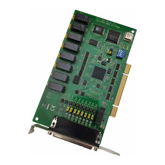
PCI-1760U
Isolated Relay Actuator and Digital Input Card
Packing List
Before installation, please make sure that you have
received the following:
• PCI-1760U card
• Driver CD
• Quick Start User Manual
If any of these items are missing or damaged, please
contact your distributor or sales representative.
User Manual
For more detailed information on this product,
please refer to the PCI-1760U User Manual on the
CD-ROM (PDF format).
CD:\Documents\Hardware Manuals\PCI\PCI-
1760U
Declaration of Conformity
FCC Class A
This equipment has been tested and found to comply with
the limits for a Class A digital device, pursuant to part 15 of
the FCC Rules. These limits are designed to provide reason-
able protection against harmful interference when the equip-
ment is operated in a commercial environment. This
equipment generates, uses, and can radiate radio frequency
energy and, if not installed and used in accordance with the
instruction manual, may cause harmful interference to radio
communications. Operation of this equipment in a residen-
tial area is likely to cause interference in which case the user
is required to correct interference at his own expense.
CE
This product has passed the CE test for environmental speci-
fications when shielded cables are used for external wiring.
We recommend the use of shielded cables. This kind of cable
is available from Advantech. Please contact your local sup-
plier for ordering information.
Overview
The PCI-1760U Relay Actuator & Isolated Digital Input
Card is a PC add-on card for the PCI bus, which was
designed with this idea in mind. This card offers the user 8
opto isolated digital inputs with isolation protection of 2500
V
for collecting digital signals under noisy environment, 8
DC
relay actuators for serving as ON/OFF control devices or
small power switches, and 2 isolated PWM (Pulse Width
Modulation) outputs for user's specific applications.
Notes
For more information on this and other Advantech prod-
ucts, please visit our websites at:
http://www.advantech.com/eAutomation
For technical support and service:
http://www.advantech.com/support/
This startup manual is for PCI-1760U
Part No. 2003176012
1
Startup Manual
Software Installation
Hardware Installation
1. Turn off your computer and unplug the power cord
and cables. TURN OFF your computer before
installing or removing any components.
2. Disconnect the power cord and any other cables
from the back of the computer.
3. Remove the cover of the computer.
4. Select an empty 5 V PCI slot. Remove the screw
that secures the expansion slot cover. Save the
screw to secure the interface card retaining
5. Grasp the upper edge of the PCI-1760U. Align the
hole in the retaining bracket with the hole on the
expansion slot and align the gold striped edge con-
nector with the expansion slot socket. Press the
card into the socket. Make sure it fits tightly.
6. Secure the PCI-1760U by screwing the mounting
bracket to the back panel of the computer.
7. Attach any accessories (37-pin D type cable, wir-
ing terminal board, etc.) to the card.
8. Replace the cover of your computer. Connect the
cables you removed in step 2.
9. Turn the computer power on
.
3rd Edition
May 2011
Advertisement

Subscribe to Our Youtube Channel
Related Manuals for Advantech PCI-1760U


Summary of Contents for Advantech PCI-1760U
- Page 1 The PCI-1760U Relay Actuator & Isolated Digital Input 5. Grasp the upper edge of the PCI-1760U. Align the Card is a PC add-on card for the PCI bus, which was designed with this idea in mind. This card offers the user 8...
- Page 2 Pin Assignments Switch and Jumper Settings We designed the PCI-1760U with ease-of-use in mind. It is a “plug and play” card, i.e. the system BIOS assigns the system resources such as base address and interrupt automatically. There are only three functions with jump- ers to be set by the user.
- Page 3 ID. We Setting relay outputs to be NC/NO set the PCI-1760U board ID as 0 at the factory. If you 6 relay outputs, RE2 ~ RE7, are single-pole single need to adjust it to other board ID, set the SW1 by refer- throw (SPST), which can be jumper set as either nor- ring to DIP switch setting.
Need help?
Do you have a question about the PCI-1760U and is the answer not in the manual?
Questions and answers