Table of Contents
Advertisement
Advertisement
Chapters
Table of Contents

Subscribe to Our Youtube Channel
Related Manuals for Bang & Olufsen BeoPlay V1-40 MKII


Summary of Contents for Bang & Olufsen BeoPlay V1-40 MKII
- Page 1 BeoPlay V1-40 MKII Type 9505 – 9508 Service Manual - version 1.0 English German, French, Italian, Spanish, Dutch, Japanese and Simplified Chinese versions are available in the Retail System 76.6 56.8 This Service Manual must be returned with the defective parts/back-up suitcase !
-
Page 2: Table Of Contents
CONTENTS Survey of modules ..............1.1 How to service ................. 1.2 Customer Service Menu ............2.1 Repair tips ................3.1 LED indications ................ 3.3 Fault flow chart ................ 3.4 Survey of plugs, pins and test points ........3.17 Adjustments ................4.1 ServiceTool ................ -
Page 3: Survey Of Modules
Survey of modules Survey of modules Speaker box T-CON PCB01 Video Engine PCB04 Power Supply Unit PCB35 ICEpower Amplifier PCB49 Backlight LED Driver PCB58 IR Receiver & Room Awareness PCB81 Wireless circuit T-CON... -
Page 4: How To Service
How to service How to service Strategy The product is to be serviced in the customer’s home. The static-protective field service kit must always be used when the product is disassembled or modules are being handled. The repair involves replacement of the module(s) or LCD panel, which are supplied in the Back-up suitcase (LCD screen not included). - Page 5 How to service Handling and cleaning Static electricity Static electricity may damage the product. STATIC ELECTRICITY MAY DESTROY THE PRODUCT Static-protective field service kit A static-protective field service kit must always be used when the product is disassembled or modules are being handled. Follow the instructions in the guide and use the ESD-mat for both old and new modules.
- Page 6 How to service Pin code IMPORTANT! If you are prompted for a pin code the first time you switch on your television, enter the pin code, provided by your retailer. The product has a 4 digit pin code, of the user´s own choice, which must be entered if the product has been disconnected from the mains for 15-30 min.
- Page 7 How to service Enter the pin code If the pin code is activated and the product is disconnected from the mains for more than 15-30 minutes, a PIN CODE menu appears as soon as the product is switched on. Enter the pin code, and the product starts again. Note: The Service code can be entered here.
-
Page 9: Customer Service Menu
Customer Service Menu Customer Service Menu Customer Service Menu ..............2.2 SW VERSIONS .................. 2.2 PUC VERSIONS ................2.2 HW VERSIONS ................. 2.3 SETTINGS ..................2.3 PICTURE ADJUSTMENTS ..............2.4 SIGNAL INFORMATION ..............2.5 SOUND ADJUSTMENTS ..............2.5 BtB ....................2.5 REPORTING .................. -
Page 10: Customer Service Menu
Customer Service Menu Customer Service Menu The Customer Service Menu gives the opportunity to customise and optimise features in the product that normally require the aid from the dealer or service centre. It may also be used to give the Service Centre the basic information about the product directly on screen and not by reading a label on the back of the product. -
Page 11: Hw Versions
Customer Service Menu HW VERSIONS This submenu shows the HW version for the different circuit boards or modules in the system. These values are read-only and cannot be modified through the menu. The following options are presented under HW versions: - Product variant - Tuner variant - Stand variant (not used) -
Page 12: Picture Adjustments
Customer Service Menu RESET TO DEFAULT RESET TO DEFAULT: Leads to a submenu where to decide how much to reset. The following options are presented in the submenu: - RESET TO FACTORY SETTINGS - RESET WEBMEDIA TO FACTORY SETTINGS Survey of reset parameters: - AV connectors are configured as NONE. -
Page 13: Signal Information
Customer Service Menu SIGNAL INFORMATION INPUT - VFREQ is the vertical frequency in Hertz. - HTOTAL is the total number of horizontal pixels including blanking period. (Not present on internal sources). - VTOTAL is the total number of vertical lines including blanking period. (Not present on internal sources). - Page 15 Customer Service Menu Customer Service Menu Customer Service Menu (Example) SW VERSION SIGNAL INFORMATION SVN REVISION 25591 INPUT: CUSTOMER SERVICE BBE REVISION 1.1.4dev VFREQ 29.97 Hz DVB STACK HTOTAL SW VERSIONS FEP APP SW 1.08a VTOTAL PUC VERSIONS FEP BOOTLOADER 1.06a RESOLUTION 720x480i...
-
Page 17: Repair Tips
Repair tips – LED indications – Fault flow chart Repair tips Check cables ..................3.2 Check for newest SW ................. 3.2 Backup ....................3.2 Restore ....................3.2 Synchronized clock for SW and PUC update........3.2 CA cards ..................... 3.2 BeoPlay V1 does not start up .............. 3.3 LED indications LED indications ................... -
Page 18: Check Cables
Repair tips Repair tips Check cables Always check all external cables as well as internal cables. Check for newest SW Always ensure to have the newest software version installed. This is done via Internet: Menu > Setup > Service > Software update > Check for updates > Automatic Download, via the ServiceTool. -
Page 19: Beoplay V1 Does Not Start Up
LED indications BeoPlay V1 does not start up To determine wether the PCB01, Video Engine is defective or not, it is possible to disconnect all other module from PCB01, Video Engine, except PCB04, Power Supply and then connect PCB01, Video engine to ServiceTool. PCB04, Power Supply must be working correctly. -
Page 20: Cannot Switch On
Fault flow chart Fault flow chart Fault symptom: Cannot switch on Confirm that Replace cable or No picture PCB04, Pxxx has re-establish mains voltage No backlight connection Possible causes: Remote Control PCB58, IR Receiver & Room Aware. PCB04, Power Supply Unit PCB01, Video Engine Is LED Is remote control... - Page 21 Fault flow chart From page Confirm voltage on PCB01, P103 pin 12, Replace PCB01, PS_BLV_ON approx. Video Engine = +5V (high) Confirm voltage on PCB01, P123 pin 4, LCD_INV_BL_ON/OFF approx. = +5V (high) Replace PCB01, and on PCB01, P123 pin 1, LCD_CTRL_PWM, Video Engine approx.
- Page 22 Fault flow chart From page 3.5 or 3.7 Confirm voltage between PCB49, P3 Replace PCB49, pin 1 and pin 2 and Backlight Driver between pin 5 and pin 6 is approx. = 50V? Check V-by-One Check PCB04, P18 Check PCB04, P18 cables W30 Replace cable or pin 9, 11 P12V_...
-
Page 23: Other Picture Faults Than No Picture
Fault flow chart Press MENU on the remote control. Is menu text easily page Fault symptom: visible? Other picture faults than no picture Possible causes: PCB01, Video Engine Is problem related Is problem related Is problem related to the tuner signal to a HDMI signal to the AV signal only... -
Page 24: Room Awareness Does Not Work
Fault flow chart Check in the MENU > SETUP > PICTURE > Fault symptom: ADVANCED SETTINGS > Room Awareness does not work ROOM ADAPTATIONS = ON Possible causes: PCB58, IR Receiver & Room Aware. PCB01, Video engine Replace PCB58, Replace PCB58, Confirm voltage on PCB01, P123 pin 1, IR Receiver &... -
Page 25: Cannot Switch To Standby
Fault flow chart Disconnect mains to television. Wait 60 sec. Fault symptom: Connect mains to Product OK Cannot switch to standby television. Does problem Possible causes: persist? Remote Control PCB58, IR Receiver & Room Aware. PCB01, Video Engine Is remote control Replace remote control Check cable... -
Page 26: No Sound Output From Internal Speakers
3.10 Fault flow chart Fault symptom: Check cables and No sound output from internal connectors between both speakers PCB35, P2 and speaker box Possible causes: PCB04, Power Supply PCB35, ICEpower Amplifier PCB01, Video Engine Speaker box (incl. NTC) Confirm voltage on Speaker units PCB01, P142, pin 1 Replace the... - Page 27 Fault flow chart 3.11 From page 3.11 Check cables between Replace cable or Confirm voltages: PCB35 re-establish on PCB35 (left), P1 and connection (left), P1 PCB04, P4 Sound OK? pin 4+5 = +12V pin 6+7 = GND pin 8+9 = -12V or similar test points on PCB04, P3 Disconnect cable from PCB35, P1.
-
Page 28: No Sound From S/P-Dif Source
3.12 Fault flow chart Check external S/P-DIF cable Reconnect or Fault symptom: connection replace cable No sound from S/P-DIF source Possible causes: PCB01, Video Engine Check settings in Connections menu, Advanced Set to Y S/P-DIF Y/N Set to Y? Connect a video source using HDMI Replace PCB01, or AV plug. -
Page 29: No Control Of Set-Top Box Using Puc
Fault flow chart 3.13 Update with the Fault symptom: correct PUC table No control of set-top box using PUC Possible causes: PCB01, Video Engine IR Remote cable Check that the IR Replace IR blaster blaster is placed on set-top box correctly on the set-top box Press MENU >... -
Page 30: Wireless - No Connection
3.14 Fault flow chart Check cable and connections between Fault symptom: Wireless Antenna rear PCB81 Reconnect or Wireless - no connection ANT1, and Wireless Antenna front PCB81 replace internal ANT0 and ANT2. antenna cable Possible causes: PCB81, Wireless circuit Connect an Internet connection cable to Replace PCB01, the Ethernet socket. -
Page 31: Ca Card Will Not Decode
Fault flow chart 3.15 Is CA module Fault symptom: inserted correctly, CA card will not decode Possible causes: CA module Smart Card On remote control press Insert CA module MENU > ACCESS CA UNITS. * correctly Is text in either/both of the two lines different (See User’s Guide from NO CARD on BeoWise) -
Page 32: Poor Or Missing Function On Btb Module, (Hotel Menu System)
3.16 Fault flow chart Fault symptom: Disconnect mains to television and to Hotel Switch Off mains to Poor or missing function on BtB System box. Wait 60 sec. television and to Connect mains to television and to Hotel module, (Hotel Menu System) Hotel System box. -
Page 33: Survey Of Plugs, Pins And Test Points
Survey of plugs, pins and test points 3.17 3.17 Survey of plugs, pins and test points 3.17 PCB01, Video Engine connectors P158 P125 P103 P126 P130 P142 P123 P132 P153 P151 P120 P121 P101 P180 P131 P152 P156 P141 P157 F1.5A P4210 S4200... - Page 34 3.18 Survey of plugs, pins and test points 3.18 3.18 Survey of plugs, pins and test points PCB49, Backlight LED Driver PWM_DIM 12VCC (12V_BLD) BL_ERR BL_ON X005 HE3113002-01...
-
Page 35: Adjustments
Adjustments – ServiceTool – Final check after repair Adjustments – ServiceTool – Final check after repair Picture adjustment ................4.2 Speaker adjustment ................4.2 ServiceTool ..................4.2 Considerations before connecting the ServiceTool to the product ..4.2 Contents in ServiceTool ..............4.2 ServiceTool functions ................ - Page 36 Adjustments – ServiceTool Picture adjustment The only situation where “picture adjustment” is needed is when an LCD is replaced. The serial number of the new LCD is entered into the ServiceTool. Then the instructions in the ServiceTool are followed. The ServiceTool will automatically ensure that the data saved for the LCD are loaded into the media processor for the optimal picture quality possible.
-
Page 37: Servicetool
ServiceTool Repair Chassis (Video Engine) Repair instructions are given. Tools are available for: Complete Backup, Complete Restore, ID Restore, Logging of the above. Screen Repair instructions are given. Tools are available for: Reading Calibration data in product, Writing Service Screen serial number, Loading production and service database, Logging of the above. Speaker Driver Repair instructions are given. Tools are available for: Reading Calibration data in product, Writing Update Calibration data, Loading production and service database,... -
Page 38: Final Check After Repair
Final check after repair Final check after repair The final check after repair, describes the activities needed to ensure that the product will be returned in perfect condition to the customer. The content is: AC leakage test. Check product information. Restore the setup and check connections, picture and sound. Final cleaning of the product. Insulation test Each set must be insulation tested after having been dismantled. Make the test when the set has been reassembled and is ready to be returned to the customer. Flashovers must not occur during the testing procedure! Make the insulation test as follows: Short-circuit the two pins of the mains plug and connect them to one of the... - Page 39 Final check after repair Cleaning Note: Do not strike the screen with hard or pointed items. Regular maintenance, such as cleaning, is the responsibility of the user. To achieve the best result, follow the instructions below. Screen Wipe dust off the screen using a dry, soft cloth. To remove stains or dirt, use a soft, lint-free, firmly wrung cloth and water. Never use alcohol or other solvents to clean any parts of the product. Some micro-fibre cloths may harm the optical coating due to their strong abrasive effect. Cabinet Wipe dust off the surfaces using a dry, soft cloth. To remove stains or dirt, use a soft, lint-free, firmly wrung cloth and a solution of water and mild detergent, such as washing-up liquid.
-
Page 41: Replacement Of Modules
Replacement of modules Replacement of modules Before replacement of modules ..............5.2 After replacement of modules ..............5.2 Release Stand/Bracket .................. 5.3 BeoPlay V1-40 BeoPlay V1-40 in service position 1 and 2 ............. 5.4 BeoPlay V1-40 in service position 3 .............. 5.5 Replace PCB35, ICEpower Amplifier(s), left or right ........ -
Page 42: Replacement Of Modules
Replacement of modules Warning – Disconnect mains and wait 45 seconds before dismantling BeoPlay V1 Power Supply and the local power supplies on the different boards must be discharged before dismantling. This is done by disconnecting from the mains, and then waiting 45 seconds before replacing any modules. Warning –... -
Page 43: Release Stand/Bracket
Replacement of modules Release Stand/Bracket Prior to bringing the BeoPlay V1-40 into a service position the stand or bracket used must be released and pulled out. - Place product on an ESD-mat, screen facing down. - Release lock . - Pull out stand/bracket rod . Note: Avoid twisting rod and cabinet when pulling. -
Page 44: Beoplay V1-40
Replacement of modules BeoPlay V1-40 BeoPlay V1-40 in service position 1 and 2 + 5.3 Release Stand/Bracket - Insert two transport pins in the top edge of the product - Insert 7 pieces of protection sheets 40” 7× - Remove cover for connectors from back part - Remove screws - Open product by lifting the back part - Turn approximately 65°... -
Page 45: Beoplay V1-40 In Service Position 3
Replacement of modules BeoPlay V1-40 in service position 3 + 5.3 Release Stand/Bracket - Insert two transport pins in the top edge of the product - Insert 7 pieces of protection sheets 40” 7× - Remove cover for connectors from back part - Remove screws - Open product by lifting the back part - Turn 180°... -
Page 46: Replace Pcb35, Icepower Amplifier(S), Left Or Right
Replacement of modules Replace PCB35, ICEpower Amplifier(s), left or right + 5.4 BeoPlay V1-40 in service position 1 For each of the amplifiers: - Disconnect cables - Remove screws TX10... -
Page 47: Replace Speaker Box (Ntc)
Replacement of modules Replace Speaker Box (NTC) + 5.4 BeoPlay V1-40 in service position 1 - Disconnect 01P142 on PCB01 and move cable away from speaker box 01P142 On both the amplifiers: - Diconnect cables 35P2 35P1 35P3 - Remove screws TX20... -
Page 48: Replace Speaker Units
Replacement of modules Replace speaker units + 5.4 BeoPlay V1-40 in service position 1 + 5.7 Disassemble speaker box - Remove screws - Turn speaker box 180° TX20 - Remove screws from the appropriate speaker units TX20 TX10 - Remove cable from the woofer ! Remember to load speaker data via ServiceTool - Remove cable from the midrange speaker ! Remember to load speaker data via ServiceTool... -
Page 49: Replace Pcb81, Wireless Circuit
Replacement of modules Replace PCB81, Wireless circuit + 5.4 BeoPlay V1-40 in service position 1 - Disconnect the three antenna cables, using the 81ANT1 81ANT2 extraction jig, U.FL series 81ANT0 Note: When replacing, the cables can be connected arbitrarily Pull - Remove nuts - Release two levers ... -
Page 50: Replace Pcb01, Video Engine
5.10 Replacement of modules Replace PCB01, Video Engine + 5.4 BeoPlay V1-40 in service position 2 01P130 Before replacement see page 5.2 01P131 - Regarding 01P120, 01P121 and 01P101 release 01P142 the cable lock 01P120 - Open cable holders 01P121 - Disconnect all external cables 01P123 - Move cables away... -
Page 51: Replace Pcb04, Power Supply Unit
Replacement of modules 5.11 Replace PCB04, Power Supply Unit + 5.4 BeoPlay V1-40 in service position 2 - Lift protection cover up - Disconnect cables 04P18 04P3 04P4 04P116 - Remove screws - Gently lift PCB04 ! Remember to remount protection cover after replacement TX10... -
Page 52: Replace Pcb58, Ir Receiver & Room Awareness
5.12 Replacement of modules Replace PCB58, IR Receiver & Room Awareness + 5.5 BeoPlay V1-40 in service position 3 - Remove screws TX10 - Lift cable locking device - Disconnect cable 58P1... -
Page 53: Replace Pcb49, Backlight Led Driver
Replacement of modules 5.13 Replace PCB49, Backlight LED Driver + 5.5 BeoPlay V1-40 in service position 3 - Disconnect cables Note: Cable locks! 49P1 ON LCD - Remove screws TX10... -
Page 54: Replace Lcd
5.14 Replacement of modules Replace LCD + 5.5 BeoPlay V1-40 in service position 3 Note: Release cables from cable holders 01P142 ! Attention: Before replacement see page 5.2 Disconnect 01P142 on PCB01 and move cable away from speaker box + 5.13 Replace PCB49, Backlight LED Driver - Open cable holders (A to C) - Release cables where glued to LCD back side - Disconnect 35P1 and 35P3 from both ICEpower... -
Page 55: Specification Guidelines For Service Use
Specification guidelines for service use SPECIFICATION GUIDELINES FOR SERVICE USE BeoPlay V1-40 MKII DESIGN Designer Anders Hermansen Type no. 9505 and 9507 Markets Albania, Andorra, Argentina, Australia, Austria, Azerbaijan, Bahrain, Belgium, Botswana, Brazil, Bulgaria, Chile, China, Croatia, Czech Republic, Cote d’Ivory, Denmark, Egypt, Estonia, Faroe Island, Finland,... - Page 56 Specification guidelines for service use PICTURE Picture optimisation VisionClear Room adaptation Automatic Picure Control Colour Calibration 10-point display calibration Contrast enhancement Adaptive contrast algorithm Global backlight dimming Motion picture improvement Adaptive film judder compensation ANALOGUE TUNER Video Type / Format Analogue: According to type and setup: B/G/L/L’/I/D/K/M...
- Page 57 Specification guidelines for service use SOUND Loudspeaker Integrated stereo speaker (centre speaker if surround sound setup) Power per Amplifier 3 × 32 W Effective Frequency Range 85 to 20,000 Hz Cabinet Principle Closed box Woofer 100 mm/4” Midrange 50 mm/2” full range type Cabinet Volume 2 ×...
- Page 58 Specification guidelines for service use Mains inlet To see the different types of mains leads see exploded view in the Retail Ordering System Live Neutral ANTENNA WLAN ANT 1 ANT 2 ANT 3 SATELLITE 14/18V; 0.4A DVB S2 tuner F-connector 75Ω, female AERIAL 5V;...
- Page 59 Specification guidelines for service use HDMI Input: 5 x Input HDMI Pin 1 TMDS. Data 2+ Pin 2 TMDS. Data 2 Shield Pin 3 TMDS. Data 2- Pin 4 TMDS. Data 1+ Pin 5 TMDS. Data 1 Shield Pin 6 TMDS.
- Page 60 Specification guidelines for service use PL 1 to PL3: 3 x Output Power Link Pin 1 Overload Data GND Pin 2 Data (chassis) 1 2 3 4 5 6 7 8 Pin 3 Signal GND Pin 4 Speaker on/off Pin 5 Power up Pin 6 Audio R out...
- Page 61 Specification guidelines for service use Vision Clear Formats (Video input formats) Name of Type of signal Vert. Freq. No. of lines + scan Aspect Ratio Source Pixel Clock Display Video Input “active” (“total”) Resolution Format Mode Format (UseCase (full frame) CVBS-576i-4:3 Composite 50 Hz...
-
Page 63: Block Diagram
Block diagram Block diagram Block diagram Mains Backlight filter SMPS Ground separation 12V_TCON Switch SMPS ±12V Standby SMPS IR Receiver & Safety insulation barrier Room Awareness Speaker box 12V_TCON 5V_SB 5V_SB ±12V ICEpower Amplifier Wireless Antenna Video Engine VE, 1.0 0.95V / 1.05V 1.8V ±11V... -
Page 65: Wiring Diagram
Wiring diagram Wiring diagram Wiring diagram Plug 18/18pins 18/18pins Plug 7211666 P103 6278743 7211666 < < P12V Power < < P12V Supply PH2mm Unit Plug 10/10pins 15/15pins Plug < < 10/10pins P12V Video Engine 72xxxxx P116 LTA400HF33 (PSU) 6278824 72xxxxx >... - Page 66 Available parts Available parts BeoPlay V1-40 MKII Incl. pos. no. 9, 17 9055 9048 9048 9056 9057 9058 9056 9059 9049 9041 Incl. 8 pcs. conductive tape & Tape kit black/white 9060 9059 9066 9050 9051 9065 9052 *9067 9042...
-
Page 67: Available Parts
Available parts BeoPlay V1-40 MKII 9041 3358516 Heat sink 9042 3160778 Cover f/LVDS cables 9043 3948019 Gasket 9044 3300222 Gasket 9045 3153656 Bracket 9046 3153600 Bracket and bushing 9047 3414016 Cover f/connectors, black 3414017 Cover f/connectors, white 9048 2515030 PCB holder... - Page 68 Available parts Screws etc. 2058075 Screw M3 x 5mm 2380033 Nut M2 x 0.4mm 2389008 Nut M3 x 7mm 3170227 Gap pad 3103066 Rubber foot 2013137 Screw 3 x 10mm 2042074 Screw 4 x 8mm 2052101 Screw 4 x 12mm 2930198 Rubber damper 2044046...
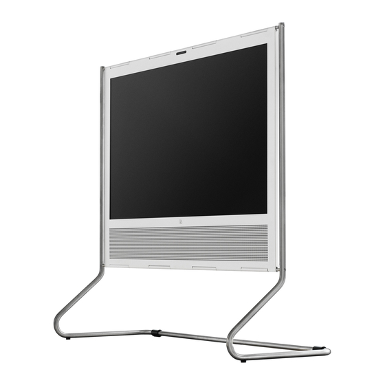
- Page 69 Available parts – Floor Stand 4724 Floor Stand 4724 1472413 Silver 9540 9540 9540 Not for sale 9540 9540 3103275 Foot 3393709 Packing Guide Can be downloaded from the Retail System / BeoWise...
- Page 70 Available parts – Table Stand 4725 Table Stand 4725 1472513 Silver 9552 9552 9552 9550 9551 9552 × 4 × 1 × 5 9552 9551 Not for sale 9550 9550 3103439 Foot 9551 3103438 Rear foot 9552 3390342 Set of accessories 3393698 Packing Guide...
- Page 71 Available parts – Wall Bracket 4752 Wall Bracket 4752 1475201 Right mounted 1475202 Left mounted 9560 9561 9562 9562 Not for sale 9562 9562 4 x cable binder 9563 2 x O-ring Ø15mm 2 x O-ring Ø20mm 2 x O-ring Ø28mm 2 x O-ring Ø35mm 9560 2894030...
- Page 72 Available parts – Ceiling Bracket 4727, 4748 - long Ceiling Bracket 4727, 4748 - long 1472713 Silver 1474813 Silver, long 9570 9571 9572 9570 9571 9573 9572 9573 9574 9572 × 6 9574 9570 3153666 Mounting plate (1 pcs) 9571 2700316 Wheel w/wire (1 pcs) 2700320...
- Page 74 Bang & Olufsen DK-7600 Struer Denmark 3538230 14-07...
Need help?
Do you have a question about the BeoPlay V1-40 MKII and is the answer not in the manual?
Questions and answers