
Related Manuals for IBM 4002-C4A


Summary of Contents for IBM 4002-C4A
- Page 1 IBM Ethernet Switch c-series Installation and User Guide Service information: 4002-C4A, -C4B, -C5A, -C5B GC27-2238-00...
- Page 3 IBM Ethernet Switch c-series Installation and User Guide Service information: 4002-C4A, -C4B, -C5A, -C5B GC27-2238-00...
- Page 4 Order publications through your IBM representative or the IBM branch office serving your locality. © Copyright International Business Machines Corporation 2009.
-
Page 5: Table Of Contents
Hardware features ......4 B48C (4002-C4A) Copper ....4 B50C (4002-C5A) Copper . - Page 6 Displaying the status of the power supplies ... . . 40 Replacing a fiber optic module ....41 IBM Ethernet Switch c-series Installation and User Guide...
- Page 7 Removing a fiber optic module ....41 Installing a new fiber optic module ....42 Cabling a fiber optic module .
- Page 8 IBM Ethernet Switch c-series Installation and User Guide...
-
Page 9: Figures
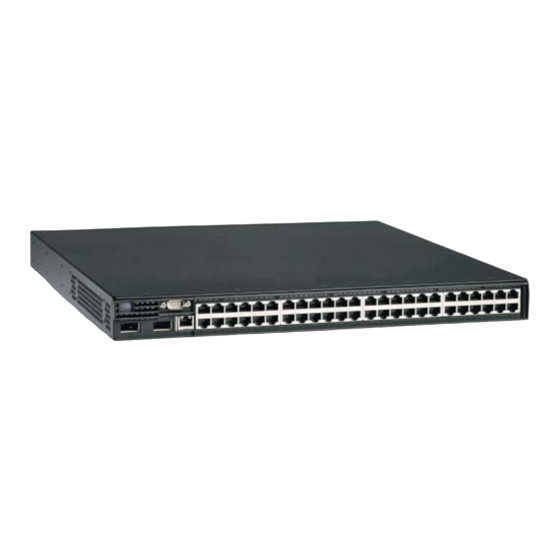
1. B50C (4002-C5A) copper Ethernet switch ..... . 3 2. B48C (4002-C4A) Copper Ethernet switch ..... . 4 3. - Page 10 IBM Ethernet Switch c-series Installation and User Guide...
-
Page 11: Tables
Tables 1. Comparable IBM and Brocade products..... . . xx 2. LEDs status descriptions ......6 3. - Page 12 IBM Ethernet Switch c-series Installation and User Guide...
-
Page 13: Preface
CD that accompanies this product. The following notices and statements are used in IBM documents. They are listed below in order of increasing severity of potential hazards. Follow the links for more detailed descriptions and examples of the notes, attention notices, caution, and danger notices in the sections that follow. -
Page 14: Notes
55 kg ( 121.2 lbs) >55kg (121.2 lb) A potential hazard of pinching the hand or other body parts between parts. P/N 18P5850-B SJ000752 A hazardous condition due to moving parts nearby. IBM Ethernet Switch c-series Installation and User Guide... -
Page 15: Danger Notices
If the symbol is... It means..A hazardous condition due to the use of a laser in the product. Laser symbols are always accompanied by the classification of the laser as defined by the U.S. Department of Health and Human Services (for example, Class I, Class II, and so forth). - Page 16 (D004) The following general electrical danger notice provides instructions on how to avoid shock hazards when servicing equipment. Unless instructed otherwise, follow the procedures in this danger notice. IBM Ethernet Switch c-series Installation and User Guide...
- Page 17 Electrical voltage and current from power, telephone, and communication cables are hazardous. To avoid a shock hazard: v Connect power to this unit only with the IBM provided power cord. Do not use the IBM provided power cord for any other product.
-
Page 18: Safety Labels
IBM Installation Planning Representative (IPR) or IBM authorized service provider. In anticipation of the equipment delivery, the final installation site should be prepared in advance such that professional movers/riggers can transport the equipment to the final installation site within the computer room. - Page 19 DANGER Hazardous voltage present. Voltages present constitute a shock hazard, which can cause severe injury or death. (L004) CAUTION: Hazardous energy present. Voltages with hazardous energy might cause heating when shorted with metal, which might result in splattered metal, burns, or both. (L005) CAUTION: Hazardous moving parts nearby (L008) CAUTION:...
-
Page 20: Rack Safety
Attempting to move the drawer partially or completely out of the rack might cause the rack to become unstable or cause the drawer to fall out of the rack. (R001 part 2 of 2) xviii IBM Ethernet Switch c-series Installation and User Guide... -
Page 21: Rack Relocation (19" Rack)
(R002) Product recycling and disposal Refer to the IBM Systems Environmental Notices and User Guide (Z125-5823) on the product documentation CD for translated environmental statements and information regarding product recycling and disposal. Preface... -
Page 22: Product Documents
Table 1 to assist you when determining which information in those publications applies to your product. Brocade products with no IBM equivalents are not listed in the table. Note that the IBM products can be ordered with additional features, while Brocade products with those additional features may be offered as separate models. -
Page 23: Getting Help
For the latest version of your product documentation, visit the web at www.elink.ibmlink.ibm.com/public/applications/publications/cgibin/pbi.cgi. Search by form number or title. For more information about this and other IBM products, visit the IBM web site: www.ibm.com/ For support information for this product and other products, see the following Web site: www.ibm.com/systems/support/. -
Page 24: How To Send Your Comments
Department GZW 9000 South Rita Road Tucson, Arizona 85744-0001 U.S.A. When you send information to IBM, you grant IBM a nonexclusive right to use or distribute the information in any way it believes appropriate without incurring any obligation to you. -
Page 25: Chapter 1. About This Guide
Chapter 1. About this guide This guide describes the IBM Ethernet Switch c-series products and includes procedures for installing the hardware, and configuring essential basic parameters such as permanent passwords and IP addresses. This guide also includes instructions for managing and maintaining the hardware. - Page 26 IBM Ethernet Switch c-series Installation and User Guide...
-
Page 27: Chapter 2. Product Overview
Chapter 2. Product overview This chapter contains an overview of the IBM Ethernet Switch B48C and B50C models. The term c-series is used to distinguish these Ethernet switch models from other IBM Ethernet switch products. These products will be referred to in the remainder of this publication by specific model when necessary to distinguish between model features and by the generic terms Ethernet switch or simply switch and switches whenever possible. -
Page 28: Software Features
59. The following figures show the front panels of the devices. B48C (4002-C4A) Copper The B48C (4002-C4A) Copper has 48-ports of 10/100/1000 RJ45 with 4 combination 100/1000 Hybrid Fiber (HF) ports, and a required AC power supply. 4 Port Combo... -
Page 29: B48C (4002-C4B) Fiber
10/100/1000 Mbps RJ45 Ethernet network interface ports (copper models) v 100/1000 Mbps SFP Ethernet network interface ports (4x combination ports on the 4002-C4A, 48x ports on the fiber models; supports SFP MSA-compliant fiber transceivers) v The B50C models also include two 10-Gigabit Ethernet uplink ports for... -
Page 30: B48C And B50C Network Interfaces
100/1000 Mbps Hybrid Fiber ports The Hybrid Fiber models of the B48C and B50C Ethernet Switches contain 48 SFP ports to which you can connect your switch to other network devices at a speed of IBM Ethernet Switch c-series Installation and User Guide... -
Page 31: Port Regions
100 Mbps or 1 Gbps. On the Copper models, there are 4 designated SFP Combination Ports that be used instead of 4 designated RJ45 Combination Ports. Into a physical port, only supported Brocade-branded fiber-optic transceivers can be used. The SFP-compliant fiber-optic modules provide an optical transceiver or physical medium dependent (PMD) interface for single or multi-mode fiber that can be used with the LAN physical layer (PHY) and support optical monitoring capabilities. -
Page 32: Ac Power Supplies
System fan speed is determined by the default temperature threshold or the manually configured temperature threshold. If desired, you can change the temperature thresholds associated with fan speed switches. IBM Ethernet Switch c-series Installation and User Guide... -
Page 33: Chapter 3. Installation
If any items are missing, please contact the place of purchase. Package contents v IBM Ethernet Switch B48C or B50C device with 1x AC power supply v CD-ROM containing software images and the user documentation (including this guide) v Adjustable rack mounting ears v 6’... -
Page 34: Summary Of Installation Tasks
IP address to the subnet on which it will be located. Initial IP address configuration is performed using the CLI with a direct serial connection. Subsequent IP address configuration can be performed using the Web management interface. IBM Ethernet Switch c-series Installation and User Guide... -
Page 35: Installation Precautions
Table 4. Summary of installation tasks (continued) Task number Task Where to find more information Once you power on the device and Chapter 4, “Connecting a c-series assign IP addresses, the system is switch to a network device,” on page ready to accept network equipment. -
Page 36: Preparing The Installation Site
(see Figure 8 on page 13). Be sure to support the power supply with your other hand. IBM Ethernet Switch c-series Installation and User Guide... -
Page 37: Ac Power Supply
net48bc013 Figure 8. AC power supply Figure 9. Power supply installation Chapter 3. Installation... -
Page 38: Installing The Device
Figure 10 on page 15. Alternative mounting positions for the rack mount ears are shown in figures Figure 11 on page 16, Figure 12 on page 17 and Figure 13 on page 18. IBM Ethernet Switch c-series Installation and User Guide... - Page 39 Figure 10. Front rack mount position Chapter 3. Installation...
- Page 40 Figure 11. 5–inch offset rack mount position IBM Ethernet Switch c-series Installation and User Guide...
- Page 41 Figure 12. Mid rack mount position Chapter 3. Installation...
-
Page 42: Reverse Rack Mount Position
#2 Phillips-head screwdriver v It will take between 12-24 screws to mount the device to the rack. Installation steps 1. Mount the device in the rack as illustrated in Figure 14 on page 19. IBM Ethernet Switch c-series Installation and User Guide... -
Page 43: Powering On The System
Figure 14. Installing the switch in a rack 2. Proceed to “Powering on the system.” Powering on the system After you complete the physical installation of the system, you can power on the system. 1. Ensure that all power supplies are fully and properly inserted and no power supply slots are uncovered. -
Page 44: Verifying Proper Operation
Position State Meaning Fan (labeled fn) Right side of front The fan tray is powered on panel and is operating normal. The fan tray is not powered on, or has been removed. IBM Ethernet Switch c-series Installation and User Guide... -
Page 45: Attaching A Pc Or Terminal
Table 5. LEDs for power and fans (continued) Position State Meaning PS1 (labeled p1) Left side of front Amber Power supply 1 is installed, but panel not connected or a fault is detected. Green steady Power supply 1 is installed and is functioning normally. - Page 46 The EIA/TIA 232 serial communication port serves as a connection point for management by a PC or SNMP workstation. IBM Ethernet Switch c-series Installation and User Guide...
-
Page 47: Chapter 4. Connecting A C-Series Switch To A Network Device
Privileged level of the EXEC mode: NetIron> enable NetIron# 2. Access the CONFIG level of the CLI by entering the following command: NetIron# configure terminal NetIron(config)# 3. Enter the following command to set the super-user password: NetIron(config)# enable super-user-password <text> © Copyright IBM Corp. 2009... -
Page 48: Configuring Ip Addresses
To enter a prefix number for a network mask, enter a forward slash ( / ) and the number of bits in the mask immediately after the IP address. For example, enter “209.157.22.99/24” for an IP address that has a network mask with 24 significant (“mask”) bits. IBM Ethernet Switch c-series Installation and User Guide... -
Page 49: Assigning An Ip Address To A Management Interface
Assigning an IP address to a management interface Instead of assigning a global IP address to the switches for system management purposes, you now assign an IP address to the management interface. The IP address is assigned to the active management module port. For example, to assign the IP address 10.0.1.1 to the management interface, do the following: 1. -
Page 50: Enabling And Disabling The Interfaces
Note: For security reasons, by default, the telnet server is disabled on the switch. To enable the telnet server and allow access via telnet to the switch from an external host, execute the following: NetIron(config)# telnet server IBM Ethernet Switch c-series Installation and User Guide... -
Page 51: Understanding How The Management Port Functions
Understanding how the management port functions You must be aware of how the system’s management port functions as described in the following: v The management port allows you to configure, monitor, and manage the c-series system only. As a result, this port has the same limited functionality as an IP host port. -
Page 52: Cabling A Fiber-Optic Module
Cleaning fiber-optic modules To avoid problems with the connection between the fiber-optic module port and the fiber cable connector, IBM strongly recommends cleaning both connectors before making this connection. In particular, dust can accumulate in either connector and cause problems such as reducing the optic launch power. -
Page 53: Chapter 5. Getting Familiar With C-Series Command Line Interface (Cli)
The CLI supports command completion, so you do not need to enter the entire name of a command or option. As long as you enter enough characters of the command or option name to avoid ambiguity with other commands or options, the CLI understands what you are typing. © Copyright IBM Corp. 2009... -
Page 54: Scroll Control
Enters the next command line in the history buffer. Ctrl-P Enters the previous command line in the history buffer. Ctrl-U; Ctrl-X Deletes all characters from the cursor to the beginning of the command line. IBM Ethernet Switch c-series Installation and User Guide... -
Page 55: Searching And Filtering Output From Cli Commands
Table 7. CLI line editing commands (continued) Ctrl-Key Combination Description Ctrl-W Deletes the last word you typed. Ctrl-Z Moves from any CONFIG level of the CLI to the Privileged EXEC level; at the Privileged EXEC level, moves to the User EXEC level. For a complete list of CLI commands and syntax information for each command, see the Configuration Guide. -
Page 56: Displaying Lines Starting With A Specified String
--More--, next page: Space, next line: Return key, quit: Control-c /telnet The results of the search are displayed: searching... telnet Telnet by name or IP address terminal Change terminal settings traceroute TraceRoute to IP node IBM Ethernet Switch c-series Installation and User Guide... -
Page 57: Using Special Characters In Regular Expressions
undelete Recover deleted file whois WHOIS lookup write Write running configuration to flash or terminal To display lines containing only a specified search string (similar to the include option for show commands) press the plus sign key ( + ) at the —More— prompt and then enter the search string. - Page 58 The beginning of the input string v The end of the input string v A blank space For example, the following regular expression matches on “100” but not on “1002”, “2100”, and so on: _100_ IBM Ethernet Switch c-series Installation and User Guide...
- Page 59 Table 8. Special characters for regular expressions (continued) Character Operation Square brackets enclose a range of single-character patterns. For example, the following regular expression matches output that contains “1”, “2”, “3”, “4”, or “5”: [1-5] You can use the following expression symbols within the brackets. These symbols are allowed only inside the brackets.
- Page 60 IBM Ethernet Switch c-series Installation and User Guide...
-
Page 61: Chapter 6. Maintaining The Hardware
Replacing a power supply. DANGER Power supplies are hot swappable. However, IBM recommends that you disconnect the power supply from AC power before installing or removing the supply. The device can be running while a power supply is being installed or removed, but the power supply itself should not be connected to a power source. -
Page 62: Ac Power Supplies
To install an AC power supply, do the following: 1. If necessary, remove the power supply locking screw located on the upper right quadrant and the lower left quadrant of the power supply (illustrated below). IBM Ethernet Switch c-series Installation and User Guide... -
Page 63: Verifying Proper Operation
Power Supply Locking Screws net48bc022 Figure 15. Power supply locking screws 2. If the empty power supply bay has a cover plate, remove the two screws near the edges of the cover plate to unlock the plate, then remove the plate. 3. -
Page 64: Displaying The Status Of The Power Supplies
24X1G PPCR: Ambience 36.0C Chip 46.62C 2X10G PPCR: Ambience 37.0C Chip 42.18C Fans are in auto mode. Temperature Monitoring Poll Period is 60 seconds --- MISC INFO --- Backplane EEPROM MAC Address: 0001.0040.7800 NetIron> IBM Ethernet Switch c-series Installation and User Guide... -
Page 65: Replacing A Fiber Optic Module
Syntax: show chassis Replacing a fiber optic module You can remove an SFP or XFP from a port and replace it with a new one while the device is powered on and running. This section provides information about the following tasks: v Removing a fiber optic module v Installing a new fiber optic module v Cabling a fiber optic module... -
Page 66: Installing A New Fiber Optic Module
1. Remove the protective covering from the fiber-optic port connectors and store the covering for future use. 2. Before cabling a fiber optic module, IBM strongly recommends cleaning the cable connectors and the port connectors. See “Cleaning the fiber optic connectors.”... -
Page 67: Upgrading The Software
When not using an SFP or XFP connector, make sure to keep the protective covering on. Upgrading the software For software upgrade instructions, see the release notes and the Configuration Guide. Note: The device must have an IP address. If the device does not already have an IP address, configure one by entering the ip address <ip-addr>... - Page 68 IBM Ethernet Switch c-series Installation and User Guide...
-
Page 69: Chapter 7. Upgrading Software Images And Configuration Files
“Upgrading the multi-service IronWare image” on page 49 - This subsection describes the procedures required for upgrading the B48C and B50C Multi-Service IronWare software image. The procedures described apply to all versions of the software. © Copyright IBM Corp. 2009... -
Page 70: Description Of The Software Images Required
The following sections describe how to use the show flash and show version commands to display this information. IBM Ethernet Switch c-series Installation and User Guide... -
Page 71: Displaying Flash Information
Displaying flash information You can display information concerning the contents of a c-series switch using the show flash command as shown in the following: NetIron#show flash ~~~~~~~~~~~~~~~~~~~~~~~~~~~~~~~~~~~~~~~~~~~~~~~~~~~~~~~~~~~~~~~~~~~~ Code Flash - Type MT28F128J3, Size 32 MB o IronWare Image (Primary) Version 3.8.0T183, Size 9049861 bytes, Check Sum ac55 Compiled on Aug 20 2008 at 04:30:22 labeled as ce03800 o Monitor Image Version 3.8.0T185, Size 347473 bytes, Check Sum 1341... -
Page 72: Displaying Version Information
The “HW:” line indicates the hardware and the type of software package enabled on the unit. The type of software package enabled on the system can be one of the following: v BASE: Indicates that the BASE software package is enabled on the unit. IBM Ethernet Switch c-series Installation and User Guide... -
Page 73: Backing Up The Current Software Images
For a detailed description of the features available in each type of software package, please refer to the Configuration Guide. Backing up the current software images Before performing a software upgrade, IBM strongly recommends backing up the following current software images in the device’s flash memory. Syntax: cp <original-file-name> <backup-file-name>... -
Page 74: Upgrading The Device's Monitor And Boot Images
These changes could represent a short-term requirement or general configuration change. To display this configuration, enter the show running-config or write terminal command at any CLI prompt. IBM Ethernet Switch c-series Installation and User Guide... -
Page 75: Replacing The Startup Configuration With The Running Configuration
Each device can have one startup configuration file and one running configuration. The startup configuration file is shared by both flash modules. The running configuration resides in DRAM. Replacing the startup configuration with the running configuration After you make configuration changes to the active system, you can save those changes by writing them to code flash. -
Page 76: Dynamic Configuration Loading
The default CLI configuration level in a configuration file is the global CONFIG level. Thus, the first command in the file must be a global CONFIG command or ” ! “. The ! (exclamation point) character means ”return to the global CONFIG level“. IBM Ethernet Switch c-series Installation and User Guide... - Page 77 Note: You can enter text following ” ! “ as a comment. However, the ” !“ is not a comment marker. It returns the CLI to the global configuration level. Note: The CLI changes to the global CONFIG level if you load the configuration as a startup-config file instead of the running-config (using the copy tftp startup-config <ip-addr>...
-
Page 78: Loading The Configuration Information Into The Running-Config
Note: Command option 23 adds configuration information to the running-config on the device, and does not replace commands. If you want to replace configuration information in the device, use ”no“ forms of the IBM Ethernet Switch c-series Installation and User Guide... -
Page 79: Erasing Image And Configuration Files
configuration commands to remove the configuration information, then use configuration commands to create the configuration information you want. Command option 30 erases the entire running-config and replaces it with the new configuration file. Erasing image and configuration files To erase software images or configuration files, use the commands described below. -
Page 80: Diagnostic Error Codes And Remedies For Tftp Transfers
SNMP, or Web management session. Wait, then retry the transfer. File type check failed. You accidentally attempted to copy the incorrect image code into the system. Retry the transfer using the correct image. IBM Ethernet Switch c-series Installation and User Guide... - Page 81 Table 14. Error codes, messages, explanations and actions (continued) Error code Message Explanation and action TFTP remote - general error. The TFTP configuration has an error. The specific error TFTP remote - no such file. message describes the error. TFTP remote - access Correct the error, then retry violation.
- Page 82 IBM Ethernet Switch c-series Installation and User Guide...
-
Page 83: Appendix. Hardware Specifications
17.44 in 17.25 in 16.5 lb 1.7 inches 44.3 cm 43.9 cm 7.5 kg 4.4 cm B50C 1 RU 17.44 in 17.25 in 17.5 lb 1.7 inches 44.3 cm 43.9 cm 7.9 kg 4.4 cm © Copyright IBM Corp. 2009... -
Page 84: Operating Environment
OSP wiring. Console port pin assignments The console port is a standard male DB-9 connector, as shown in Figure 16 on page 61. IBM Ethernet Switch c-series Installation and User Guide... -
Page 85: Management Port Pin Assignments
Pin Assignment Pin Number Switch Signal DB-9 male Reserved TXD (output) RXD (input) Reserved Reserved CTS (input) RTS (output) Reserved Figure 16. Console port pin and signalling details Most PC serial ports require a cable with a female DB-9 connector. However, terminal connections will vary, requiring a cable with either a DB-9 or DB-25 connector, male or female. - Page 86 Table 19. Management port pin assignments (continued) Pin number MDI-X ports Not used (10BaseT) CMT (100BaseTX) Not used (10BaseT) CMT (100BaseTX) Not used (10BaseT) CMT (100BaseTX) Not used (10BaseT) CMT (100BaseTX) IBM Ethernet Switch c-series Installation and User Guide...
-
Page 87: Notices
The materials at those web sites are not part of the materials for this IBM product and use of those web sites is at your own risk. -
Page 88: Trademarks
IBM, the IBM logo, and ibm.com are trademarks or registered trademarks of International Business Machines Corporation in the United States, other countries, or both. A complete and current list of other IBM trademarks is available on the Web at http://www.ibm.com/legal/copytrade.shtml Linux is a registered trademark of Linus Torvalds in the United States, other countries, or both. -
Page 89: Index
12 securing access 23 intellectual property 63 Command completion CLI 29 network mask 24 comments IP address sending xxii assigning 24 CONFIG Level 23 CIDR notation 24 Configuration displaying 50 erasing 55 saving 50 © Copyright IBM Corp. 2009... - Page 90 21 Weight preface xi warning 19 Privileged EXEC level 23 product documents xx rack safety xviii rack relocation safety xix rack safety xviii reader comment form xxii Redundant Power Supply Caution 10 IBM Ethernet Switch c-series Installation and User Guide...
- Page 91 When you send comments to IBM, you grant IBM a nonexclusive right to use or distribute your comments in any way it believes appropriate without incurring any obligation to you. IBM or any other organizations will only use the personal information that you supply to contact you about the issues that you state on this form.
- Page 92 Readers’ Comments — We’d Like to Hear from You Cut or Fold Along Line GC27-2238-00 Fold and Tape Please do not staple Fold and Tape _ _ _ _ _ _ _ _ _ _ _ _ _ _ _ _ _ _ _ _ _ _ _ _ _ _ _ _ _ _ _ _ _ _ _ _ _ _ _ _ _ _ _ _ _ _ _ _ _ _ _ _ _ _ _ _ _ _ _ _ _ _ _ _ _ _ _ _ _ _ _ _ _ _ _ _ _ _ _ _ _ _ _ _ _ _ _ _ _ NO POSTAGE NECESSARY IF MAILED IN THE...
- Page 94 Part Number: 45W3139 Printed in USA GC27-2238-00 80218- 001...
Need help?
Do you have a question about the 4002-C4A and is the answer not in the manual?
Questions and answers