Sign In
Upload
Download
Table of Contents
Contents
Add to my manuals
Delete from my manuals
Share
URL of this page:
HTML Link:
Bookmark this page
Add
Manual will be automatically added to "My Manuals"
Print this page
×
Bookmark added
×
Added to my manuals
Manuals
Brands
IBM Manuals
Switch
8960-F64
Hardware installation manual
IBM 8960-F64 Hardware Installation Manual
64 port 32g gen 6 switch
Hide thumbs
1
Table Of Contents
2
3
4
5
6
7
8
9
10
11
12
13
14
15
16
17
18
19
20
21
22
23
24
25
26
27
28
29
30
31
32
33
34
35
36
37
38
39
40
41
42
43
44
45
46
47
48
49
50
51
52
53
54
55
56
57
58
59
60
61
62
63
64
65
66
67
68
69
70
71
72
73
74
75
76
77
78
79
80
81
82
83
84
85
86
87
88
89
90
91
92
93
94
95
96
97
98
99
100
page
of
100
Go
/
100
Contents
Table of Contents
Bookmarks
Table of Contents
Table of Contents
Preface
Document Conventions
Text Formatting Conventions
Command Syntax Conventions
Notes, Cautions, and Warnings
Resources
Contacting Technical Support
Document Feedback
About this Document
Supported Hardware and Software
What's New in this Document
Device Overview
Hardware Features
License Options
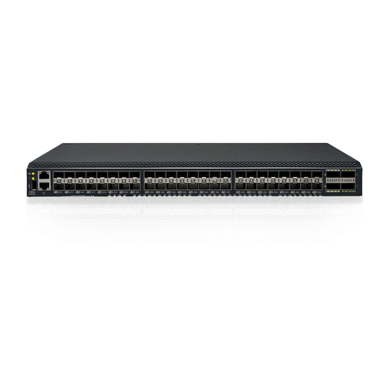
Port-Side View
Nonport-Side View
Device Management Options
Preparing for Installation
Safety Precautions
General Precautions
ESD Precautions
Power Precautions
Lifting and Weight-Related Precautions
Laser Precautions
Facility Requirements
Quick Installation Checklist
Shipping Carton Contents
Mounting the Device
Mounting Options
Precautions Specific to Mounting
Standalone Installation
Universal Four-Post Rack Installation
Installation Requirements
Time and Items Required
Flush-Front Mounting
Flush-Rear (Recessed) Mounting
Universal Two-Post Rack Installation
Installation Requirements
Time and Items Required
Flush-Front Mounting
MID-Mounting
Initial Setup and Verification
Items Required
Providing Power to the Device
Establishing a First-Time Serial Connection
Configuring the IP Address
Using DHCP to Set the IP Address
Setting a Static IP Address
Setting the Date and Time
Setting the Time Zone
Synchronizing Local Time with an External Source
Customizing the Chassis Name and Switch Name
Establishing an Ethernet Connection
Setting the Domain ID
Verifying Correct Operation
Backing up the Configuration
Powering down the Device
Installing the Transceivers and Cables
Time and Items Required
Precautions Specific to Transceivers and Cables
Cleaning the Fiber-Optic Connectors
Managing Cables
Installing an SFP+ Transceiver
Replacing an SFP+ Transceiver
Installing a QSFP Transceiver
Replacing a QSFP Transceiver
Verifying the Operation of New Transceivers
Monitoring the Device
Interpreting Port-Side Leds
System Power LED
System Status LED
FC Port Status LED
QSFP Port Status LED
Interpreting Nonport-Side Leds
Power Supply and Fan Assembly Status LED
Interpreting the POST Results
Interpreting the BOOT Results
Running Diagnostic Tests
Power Supply and Fan Assembly
Power Supply and Fan Assembly FRU Overview
Precautions Specific to the Power Supply and Fan Assemblies
Identifying the Airflow Direction
Power Supply and Fan Assembly Status LED
Power Supply and Fan Assembly Unit Fault Indicators
Power Supply and Fan Assembly Task Guide
Time and Items Required
Recording Power Supply and Fan Assembly Critical Information
Removing a Power Supply and Fan Assembly
Inserting a New Power Supply and Fan Assembly
Verifying the Operation of the Power Supply and Fan Assemblies
Technical Specifications
Regulatory Statements
BSMI Statement (Taiwan)
Canadian Requirements
CE Statement
China CC Statement
China ROHS
FCC Warning (US Only)
Germany
KCC Statement (Republic of Korea)
VCCI Statement
Cautions and Danger Notices
Cautions
Danger Notices
Advertisement
Quick Links
1
Hardware Features
2
Device Overview
3
Port-Side View
4
License Options
5
Power Supply and Fan Assembly Fru Overview
Download this manual
IBM 64 Port 32G Gen 6 Switch
(8960-F64/8960-N64)
Hardware Installation Guide
Table of
Contents
Previous
Page
Next
Page
1
2
3
4
5
Advertisement
Table of Contents
Need help?
Do you have a question about the 8960-F64 and is the answer not in the manual?
Ask a question
Questions and answers
Related Manuals for IBM 8960-F64
Switch IBM 8960-N64 Hardware Installation Manual
64 port 32g gen 6 switch (100 pages)
Switch IBM 8960-F96 Installation, Service And User Manual
(116 pages)
Switch IBM Storage Networking SAN128B-6 Installation, Service And User Manual
(116 pages)
Switch IBM 8239 Token-Ring Stackable Hub Setup And User Manual
(141 pages)
Switch IBM 8285 Nways Installation And User Manual
Atm workgroup switch (265 pages)
Switch IBM BM 8270 Brochure & Specs
Nways lan switch family (8 pages)
Switch IBM 600 Product Overview
8270 nways lan switch family (13 pages)
Switch IBM 02L1333 Quick Reference Manual
8271 nways ethernet lan switch atm oc-3c module (6 pages)
Switch IBM Nways 8265 Problem Determination And Service Manual
(174 pages)
Switch IBM 8265 Nways ATM Switch Installation Manual
(102 pages)
Switch IBM Nways 8265 Product Description
Atm switch (100 pages)
Switch IBM 8265 User Manual
Nways atm switch (212 pages)
Switch IBM 8265 Site Preparation Manual
Nways atm switch (164 pages)
Switch IBM 8275-416 User Manual
High performance ethernet workgroup switch (157 pages)
Switch IBM 8275 User Manual
High performance ethernet workgroup switch (110 pages)
Switch IBM G8316 Installation Manual
System networking rack switch (84 pages)
This manual is also suitable for:
8960-n64
Table of Contents
Save PDF
Print
Rename the bookmark
Delete bookmark?
Delete from my manuals?
Login
Sign In
OR
Sign in with Facebook
Sign in with Google
Upload manual
Upload from disk
Upload from URL


Need help?
Do you have a question about the 8960-F64 and is the answer not in the manual?
Questions and answers