Sign In
Upload
Manuals
Brands
Fuji Electric Manuals
Inverter
FRENIC Series
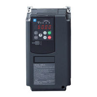
Fuji Electric FRENIC Series Manuals
Manuals and User Guides for Fuji Electric FRENIC Series. We have
1
Fuji Electric FRENIC Series manual available for free PDF download: User Manual
Fuji Electric FRENIC Series User Manual (970 pages)
High-Performance, Multi-Function Inverter
Brand:
Fuji Electric
| Category:
Inverter
| Size: 25 MB
Table of Contents
Setting Run Commands with External Signals (Terminal [Fwd, [Rev]) ············· 4-47
134
Table of Contents
134
2 ] Motor Protection with Thermistor
172
1 ] Copying Function Codes Using the Keypad
173
2 ] Entering Function Codes Directly from the Keypad
173
Setting Function Codes When Switching from a Conventional Model
173
Switching from FRENIC-MEGA (G1S)
173
3 ] Entering Function Codes from PC Loader
174
Switching from FRENIC5000G11S/P11S or FRENIC5000G9S/P9S
174
Check Points During a Test Run
175
Operation Check
175
Test Run Procedure
175
Adjusting the Function Code for Motor Control
176
Selecting a Frequency Command Source
178
Setting the Frequency from the Keypad
178
Setting the Frequency with an External Potentiometer (Variable Resistor)
179
Setting the Frequency with Multistep Frequency Selection (1 Speed, 2 Speed, Etc.)
180
Selecting a Run Command Source
181
Setting Run Commands from the Keypad
181
Setting Run Commands with External Signals (Terminal [FWD, [REV])
181
Table of Contents
184
Measuring the Capacitance of DC Link Bus Capacitor under Ordinary Operating Conditions at Power Shutdown
418
A, B, R Codes (Motor 2 to 4 Parameters)
445
B, R Codes (Speed Control 3 and 4 Parameters)
450
J Codes (Applied Functions)
451
1 ] PID Command with Keypad (J02 = 0, Factory Default)
452
2 ] PID Command by Analog Inputs (J02 = 1)
453
3 ] PID Command with UP/DOWN Control (J02 = 3)
454
4 ] PID Command Via Communications Link (J02 = 4)
455
5 ] Overload Stop Function
469
6 ] Brake Control Signal
471
1 ] Speed Control
480
D Codes (Applied Functions 2)
480
2 ] Line Speed Control
490
3 ] Master-Follower Operation
493
4 ] Hoist Function
527
5 ] Position Control
534
6 ] Setting Example for Conveyor Performing Sizing by Position Control
551
U Codes (Customizable Logic Operation)
561
U1 Codes (Customizable Logic Operation)
593
Y Codes (Link Functions)
598
K Codes (Keypad Functions)
605
Chapter 6 Troubleshoooting
611
Protective Functions
615
Before Proceeding with Troubleshooting
617
Alarm Code List
618
If an Alarm Code Appears on the LED Monitor
618
1 ] Ca1 to Ca5 User-Defined Alarm
622
2 ] Cof Current Input Terminals [C1], [C2] Signal Line Break
622
3 ] Dba Braking Transistor Broken
622
Causes, Checks and Measures of Alarms
622
4 ] Dbh Braking Resistor Overheat
623
5 ] Ecf en Circuit Failure
623
6 ] Ecl Customizable Logic Error
624
7 ] Ef Ground Fault Protection (FRN0032G2S-2G/FRN0018G2□-4G or Above)
624
8 ] Er1 Memory Error
624
10 ] Er3 CPU Error
625
11 ] Er4 Option Communication Error
625
12 ] Er5 Option Error
625
9 ] Er2 Keypad Communication Error
625
13 ] Er6 Operation Error
626
14 ] Er7 Tuning Error
627
Er8 RS-485 Communication Error (Communication Port 1)/ Erp RS-485 Communication Error (Communication Port 2)
628
16 ] Erd Step-Out Detection/Detection Failure of Magnetic Pole Position at Startup
629
17 ] Erc Magnetic Pole Position Detection Error
630
18 ] Ere Speed Inconsistency / Excessive Speed Deviation
631
19 ] Erf Data Saving Error During Undervoltage
632
20 ] Erh Hardware Error
632
21 ] Ero Positioning Control Error
632
22 ] Err Simulated Failure
633
23 ] Fus Blown Fuse
633
24 ] Fal DC Fan Lock
633
25 ] Lin Input Phase Loss
633
Chapter 7 Maintenance and Inspection
659
Inspection Interval
662
Daily Inspection
663
Periodic Inspection
664
Periodic Inspection 1--Before the Inverter Is Powered on or after It Stops Running
664
Periodic Inspection 2--When the Inverter Is on or It Is Running
666
List of Periodic Replacement Parts
667
Judgment on Service Life
668
At Time of Shipment
670
2 ] Measuring the Capacitance of the DC Link Bus Capacitor
671
3 ] Early Warning of Lifetime Alarm
671
Measuring the Amount of Electricity in Main Circuit
672
Insulation Test
673
Insulation Test of Control Circuit
673
Insulation Test of External Main Circuit and Sequence Control Circuit
673
Megger Test of Main Circuit
673
1 ] Free of Charge Warranty Period and Warranty Range
674
Inquiry Request
674
Product Inquiries and Warranty
674
Product Warranty
674
2 ] Exclusion of Liability for Loss of Opportunity, Etc
675
3 ] Repair Period after Production Stoppage, Spare Parts Supply Period
675
4 ] Delivery Conditions
675
5 ] Service Description
675
6 ] Applicable Scope of Service
675
Chapter 8 Block Diagrams for Control Logic
677
Meanings of Symbols Used in the Control Block Diagrams
679
Frequency Setting Section
680
Operation Command Section
683
PID Control Section (for Processing)
684
PID Control Section (for Dancer)
685
Position Control Section
686
Common
687
Control Section
687
V/F Control
687
Without Speed Sensor
688
3 ] with Speed Sensor
689
Common
690
Vector Control
690
2 ] Torque Command / Torque Limit
691
3 ] Speed Control / Torque Control
692
4 ] Speed Limit and over Speed Protection Processing
693
Motor Drive
694
6 ] PMSM Drive
695
FM Output Section
697
Chapter 9 Communication Functions
699
Overview of RS-485 Communication
701
Common Specifications
702
1 ] RS-485 COM Port 1 (RJ-45 Connector for Keypad Connection) Specification
703
2 ] RS-485 COM Port 2 (Terminal Block) Specifications
703
Communication Terminal Specifications
703
Connection Method
704
1 ] Converter
706
2 ] Requirements for the Cable (COM Port 1: for RJ-45 Connector)
706
3 ] Requirements for the Cable (COM Port 2: for RS-485 Terminal Block Connection)
706
4 ] Branch Adapter for Multi-Drop
706
Connection Devices
706
Noise Suppression
707
FRENIC Loader Overview
708
Specifications
708
Chapter 10 Selecting Optimal Motor and Inverter Capacities
709
Motor Output Torque Characteristics
711
Selection Procedure
713
1 ] General Equation
716
2 ] Obtaining the Required Force F
716
Equations for Selections
716
Load Torque During Constant Speed Running
716
1 ] Calculation of Moment of Inertia
718
Acceleration and Deceleration Time Calculation
718
2 ] Calculation of the Acceleration Time
720
3 ] Calculation of the Deceleration Time
721
4 ] Calculating Non-Linear Acceleration/Deceleration Time
721
5 ] Calculating Non-Linear Deceleration Time
722
1 ] Calculation of Regenerative Energy
723
Heat Energy Calculation of Braking Resistor
723
Calculating the RMS Rating of the Motor
724
Precautions in Making the Selection
725
Selecting the Inverter Rating Specification (HHD/HND)
725
Guideline for Selecting Inverter Specification and Capacity
726
Chapter 11 Selecting Peripheral Equipment
727
Configuring the FRENIC-MEGA
729
Size of Current for each Part of the Inverter
730
Function Overview
733
Molded Case Circuit Breakers (MCCB), Earth Leakage Circuit Breakers (ELCB)
733
Connection Example and Criteria for Selection of Circuit Breakers
734
Surge Killers
740
Lightning Surge Protection Device SPD
741
Surge Absorbers
742
Filter Capacitors for Suppressing am Radio Band Noise
743
1 ] Selection Procedure
744
2 ] Notes on Selection
744
Braking Resistors (DB) and Braking Units
744
Selecting a Braking Resistor
744
1 ] Standard Type
745
2 ] 10%ED Type
745
Overview of Braking Resistors (DB) and Braking Units
745
3 ] Overview of Braking Unit
746
Specification
747
External Dimensions
750
High Power Factor Power Supply Regeneration PWM Converters (RHC Series)
752
Overview
752
1 ] Standard Specification
753
Specification
753
2 ] Common Specifications
757
Function Specifications
759
Device Configuration
764
External Dimensions
767
1 ] Standard Specification
776
Compact Power Regeneration PWM Converter
776
Specifications
776
Chapter 12 Specifications
865
Standard Specifications 1 (Basic Type)
867
Three-Phase 200V Series
867
Three-Phase 400 V Series
870
Standard Specifications 2 (Type with Built-In EMC Filter)
874
Three-Phase 400V Series
874
Common Specifications
878
Appendices
909
Appendix A Trouble-Free Use of Inverters (Notes on Electrical Noise)
911
Effect of Inverters on Other Devices
911
1 ] Effect on am Radios
911
2 ] Effect on Telephones
911
3 ] Effect on Pressure Sensors
911
5 ] Effect on Proximity Switches
911
Noise
912
1 ] Inverter Operating Principle and Noise
912
2 ] Types of Noise
913
Measure
915
1 ] Noise Prevention Prior to Installation
915
2 ] Implementation of Noise Prevention Measures
916
3 ] Noise Prevention Examples
919
Appendix B Japanese Guideline for Suppressing Harmonics by Customers Receiving High Voltage or Special High Voltage (General-Purpose Inverters)
923
Application of General-Purpose Inverters
923
1 ] Application for Other than Special Customers
923
2 ] Application for "Guideline for Suppressing Harmonics by Customers Receiving
923
High Voltage or Special High Voltage
923
Complying with "Guideline for Suppressing Harmonics by Customers Receiving
925
High Voltage or Special High Voltage
925
1 ] Calculation of Equivalent Capacity (Pi)
925
2 ] Harmonic Current Calculation
926
3 ] Examples of Calculation
928
Appendix C Effect on Insulation of General-Purpose Motors Driven with 400 V Class Inverters
929
Generating Mechanism of Surge Voltages
929
Effect of Surge Voltages
930
Countermeasures against Surge Voltages
931
1 ] Using a Surge Suppressor Unit (SSU)
931
2 ] Suppressing Surge Voltages
931
3 ] Using Motors with Enhanced Insulation
931
Advertisement
Advertisement
Related Products
Fuji Electric Frenic-Sce
Fuji Electric FRENIC-Multi
Fuji Electric FRENIC-Lift series
Fuji Electric FRENIC-Multi Series
Fuji Electric FRENIC-Ace series
Fuji Electric frenic-hvac
Fuji Electric FRENIC5000G11S Series
Fuji Electric FRENIC5000P11S Series
Fuji Electric FRENIC-AQUA series
Fuji Electric FRENIC-HVAC series
Fuji Electric Categories
Air Conditioner
Inverter
Measuring Instruments
Controller
Control Unit
More Fuji Electric Manuals
Login
Sign In
OR
Sign in with Facebook
Sign in with Google
Upload manual
Upload from disk
Upload from URL