
Subscribe to Our Youtube Channel
Related Manuals for Fuji Electric FRENIC-Multi LM-1 Series


Summary of Contents for Fuji Electric FRENIC-Multi LM-1 Series
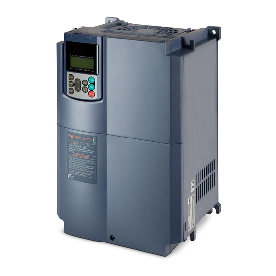
- Page 1 STARTING GUIDE FRENIC-Multi LM-1 High performance compact inverter for lift applications 3 ph 400 V 0.4 kW – 15 kW 3 ph 200 V 0.1 kW – 15 kW SG_Multi-LM1_EN_1.4.3...
- Page 2 Index Version Date Written Checked Approved 1.1.0 - First Lift version 05.09.07 J.Alonso S.Ureña S.Ureña 1.2.0 - Second version (RESTILING) 05.02.08 J.Alonso S.Ureña S.Ureña 1.2.1 - 1ph 200 V series removed 26.06.08 J.Alonso S.Ureña S.Ureña - Information of S-curves corrected - New parameters added in chapter 9 - Keypad menus information added 1.2.2...
-
Page 3: Table Of Contents
CONTENTS Chapter Page SAFETY INFORMATION AND CONFORMITY TO STANDARDS Safety information Conformity to European standards TECHNICAL DATA Three-phase 400 V class series Three-phase 200 V class series Over-rating table for 400 V class series MECHANICAL INSTALLATION Operating Environment Installing the inverter WIRING Removing the terminal cover and the main circuit terminal block cover Wiring for main circuit terminals and grounding terminals... - Page 4 Preface Thank you for purchasing our FRENIC-Multi LM1 series of inverters. This product is designed to drive a three-phase induction motor for lift applications. Read through this manual and be familiar with correct handling and operation of this product. Improper handling may result in incorrect operation, a short life, or even a failure of this product as well as the motor.
-
Page 5: Safety Information And Conformity To Standards
1. SAFETY INFORMATION AND CONFORMITY TO STANDARDS 1.1 Safety information Read this manual thoroughly before proceeding with installation, connections (wiring), operation, or maintenance and inspection. Ensure you have sound knowledge of the device and familiarize yourself with all safety information and precautions before proceeding to operate the inverter. - Page 6 Wiring • When wiring the inverter to the power supply, insert a recommended moulded case circuit breaker (MCCB) or residual-current- operated protective device (RCD)/earth leakage circuit breaker (ELCB) (with overcurrent protection) in the path of power lines. Use the devices within the recommended current range. •...
-
Page 7: Conformity To European Standards
EMC compliant filter is connected to them. General purpose inverters are subject to the regulations set forth by the Low Voltage Directive in the EU. Fuji Electric declares the inverters bearing a CE marking are compliant with the Low Voltage Directive. -
Page 8: Technical Data
2. TECHNICAL DATA 2.1 Three-phase 400 V class series Items Specifications Type (FRN□□□E1E/S-4LM1) 0.75 Nominal applied motor [kW] 0.75 Rated capacity [kVA] Rated voltage [V] Three-phase 380 to 480 V (With AVR) Rated current [A] (*1) Overload capability 150 % of rated current for 1min or 200 % of rated current for 0.5 s Rated frequency 50/60 Hz Main power supply... -
Page 9: Over-Rating Table For 400 V Class Series
2.3 Over-rating table for 400 V series Maximum Inverter I rated Overload Time Overload Time Size motor POWER 4 kW 10.4 5.5 kW 7.5 kW 20.8 11 kW 27.6 15 kW 34.5 Rated current for Ta= 45 ºC, Cf= 8 kHz, ED=40 % Chapter 2: Technical data _______________________________________________________________________________________________________________... -
Page 10: Mechanical Installation
3. MECHANICAL INSTALLATION 3.1 Operating Environment Install the inverter in an environment that satisfies the requirements listed in Table 3.1. Table 3.1 Environmental Requirements Table 3.2 Output Current Derating Factor in Relation to Altitude Item Specifications Output current Altitude Site location Indoors derating factor Ambient... -
Page 11: Wiring
4. WIRING Follow the below procedure (In the following description, the inverter has already been installed). 4.1 Removing the terminal cover and the main circuit terminal block cover (1) For inverters with a capacity of less than 5.5 kW To remove the terminal cover, put your finger in the dimple of the terminal cover (labelled "PULL"), and then pull it up toward you. - Page 12 When mounting the main circuit terminal block cover, fit it according to the guide on the inverter. Figure 4.3 Mounting the main circuit terminal block cover (For Inverters with a Capacity of 5.5 and 7.5 kW) (3) For inverters with a capacity of 11 and 15 kW To remove the terminal cover, first loosen the terminal cover fixing screw, put your finger in the dimple of the terminal cover (labelled "PULL"), and then pull it up towards you.
-
Page 13: Wiring For Main Circuit Terminals And Grounding Terminals
4.2 Wiring for main circuit terminals and grounding terminals The diagram below shows main circuit and grounding terminals connexion DC reactor When installing DC reactor remove the bridge between P1 and P+ Input line fuses EMC Filter 2 Motor contactors L1 / R Motor L2 / S... -
Page 14: Wiring For Control Circuit Terminals
4.3 Wiring for control circuit terminals The diagram below shows a basic connection example for running the inverter with terminal commands. Analog Inputs Slide switches on the Keypad connector or control board for RS 485 (Modbus RTU) hardware configuration FRENIC-Multi LM1 Voltage power supply +24 VDC Lift direction: Relay output... - Page 15 Figure 4.9: Connection using external power supply Terminal Function description of the digital inputs Left rotation direction of the motor seen from the shaft side. Depending on the mechanical set up this can be UP or DOWN direction of the cabin Right rotation direction of the motor seen from the shaft side.
- Page 16 Terminal Function description of the transistor outputs Motor brake control. Normally the lift controller will also determine the status of the motor brake (depending on the safety chain status). Motor contactors control. Normally the lift controller will also determine the status of the motor contactors (depending on the safety chain status).
-
Page 17: Setting Up The Slide Switches
4.5 Setting up the slide switches Before changing the switches, turn OFF the power and wait more than five minutes. Make sure that the LED monitor is turned OFF. Also, make sure, using a multimeter or a similar instrument, that the DC link bus voltage between the terminals P (+) and N (-) has dropped below the safe voltage (+25 VDC). -
Page 18: Operation Using The Keypad
5. OPERATION USING THE KEYPAD 7-segment LED monitor indicators As shown on the right, the keypad consists of a four- digit LED monitor, six keys, and five LED indicators. The keypad allows you to run and stop the motor, monitor running status, and switch to the menu Program/ mode. - Page 19 FRENIC-Multi LM1 features the following three operation modes: I Running mode: This mode allows you to enter run/stop commands in regular operation. You can also monitor the running status in real time. I Programming mode: This mode allows you to configure function code data and check a variety of information relating to the inverter status and maintenance.
- Page 20 Keypad menus Partial menu list can be accessed by pressing Here you can find most important menus. Data Setting (From 1.F_ _ to 1.o_ _ ) Selecting each of these function codes enables its data to be displayed/changed. Data Checking (2.rEP) Display only function codes that have been changed from their factory defaults.
-
Page 21: Setting
6. SETTING 6.1 Basic setting for induction motors Set the following function codes according to motor ratings and application values. For the motor, check the rated values printed on the nameplate of the motor. Factory Basic Setting Function Meaning setting Depends on the Maximum rotating speed (Hz) 50 Hz... -
Page 22: Additional Setting
Auto tuning procedure 1. Is the motor correctly connected? 2. Turn on inverter mains supply. 3. Switch the operation mode from remote to local (setting F02 = 2 or 3). 4. Please, set the functions described in the previous table (6.1). 5. -
Page 23: Setting The Speed Profile
6.4 Setting the speed profile The setting of the speed profile includes: Travelling speed Acceleration and deceleration times S-curves Soft start For the high speed, each intermediate speed and creep speed the acceleration, deceleration times and S-curves can be set according the table 6.3 (below). The setting of the S-curve means the speed change in terms of percentage of the maximum speed (F03) used for the acceleration change. -
Page 24: Complete Time Diagram For Normal Travel
6.5 Complete time diagram for normal travel Speed F20/F25/J71 F23/J69 Time BX/BBX SW52-2 Magnet contactor OUTPUT BRKS Mechanical Release Brake J68 (%) Sign Contents Function Explanation of inverter status Inverter status Magnet contactor operation delay time The inverter waits to begin the output from operation command ON to Inverter stopped Magnet contactor operation delay waiting... -
Page 25: Special Operations
7. SPECIAL FUNCTIONS 7.1 Rescue operation The rescue operation enables the inverter (during undervoltage situation) to move the elevator cage to the nearest floor. The rescue is done by means of a UPS power supply. Requirements for rescue operation: The BATRY function (63) must be assigned to any digital input terminal. From factory •... -
Page 26: Auto-Resetting Operation
The sequence of signals has to be done as is shown in following diagram: Main power BATRY UPS power supply UPS operation (0.5 s) (0.1 s) allowable zone DC link bus voltage Edc Undervoltage level o80: UPS Operation level Output Frequency S-curve acce./dece. -
Page 27: Torque Boost Gain
7.3 Torque boost gain A torque boost gain can be set in FRENIC-Multi lift. Torque boost is used to adjust output voltage in order to guarantee a sufficient torque. A different torque boost gain can be adjusted for booth normal and rescue operation. Recommended Function Code Drive mode... -
Page 28: Function Codes (Parameters)
8. FUNCTION CODES (PARAMETERS) Function codes enable the FRENIC-Multi LM1 series of inverters to be set up to match your system requirements. The most important function codes are classified into seven groups: Fundamental Functions (F codes), Extension Terminal Functions (E codes), Control Functions of Frequency (C codes), Motor Parameters (P codes), High Performance Functions (H codes), Application Functions (J codes), and Option Functions (o codes). - Page 29 E codes: Extension terminal functions Code Name Data setting range Default setting Terminal [X1] Function Selecting function code data assigns the corresponding function to terminals [X1] to [X5] as listed below. Terminal [X2] Function (1000): Select multi-frequency ( SS1 ) Terminal [X3] Function (1001): Select multi-frequency...
- Page 30 C codes: Control functions of frequency Code Name Data setting range Default setting Speed 2 (Run Speed) 0.00 to 400.0 Hz 50.00 Hz Speed 3 (Maintenance Speed) 25.00 Hz Speed 4 (Creep Speed) 5.00 Hz Speed 5 (Run Speed) 10.00 Hz Speed 6 (Run Speed) 10.00 Hz Speed 7 (Maintenance Speed)
-
Page 31: Troubleshooting
J codes: Application functions Code Name Data setting range Default setting Overload Stop of UPS Operation Torque (Detection value) Current Input power (Detection level : UPS capacity) 20 to 200% 100 % (Mode selection) Disable Decelerate to stop Coast to a stop (Operation condition) Enable at constant speed and during deceleration Enable at constant speed... - Page 32 Alarm code Alarm name Alarm description External braking resistor Overheating of the external braking resistor overheat Overload protection IGBT internal temperature calculated from the output current and from the temperature inside the inverter is over the preset value. External alarm input A digital input is programmed with the function THR (9) and has been deactivated.
- Page 33 Fax: +49 (0)6400 9518 22 hgneiting@fujielectric.de mrost@fujielectric.de Switzerland Spain Fuji Electric Europe GmbH Fuji Electric Europe GmbH, Sucursal en España ParkAltenrhein Ronda Can Fatjó 5, Edifici D, Local B 9423 Altenrhein Parc Tecnològic del Vallès Tel.: +41 71 85829 49 08290 Cerdanyola (Barcelona) Fax.: +41 71 85829 40...
Need help?
Do you have a question about the FRENIC-Multi LM-1 Series and is the answer not in the manual?
Questions and answers