
Related Manuals for klover E-CONNECT 1700


Summary of Contents for klover E-CONNECT 1700
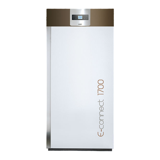
- Page 1 Machine Translated by Google E-CONNECT 1700 INSTRUCTIONS FOR USE CS.ECN1700.IST-1 / Rev 1.0...
-
Page 2: Table Of Contents
Copyright © 2021 KLOVER srl All rights reserved. It is forbidden to reproduce any part of this manual, in any form, without the explicit written permission of KLOVER srl. The contents of this manual can be changed without notice. Every care has been taken in the collection and verification of the documentation contained in this manual;... -
Page 3: Introduction
- The installation and commissioning of the appliance must be carried out by competent personnel aware of compliance with the safety standards in force, who will assume full responsibility for the final installation and consequent good operation. There will be no liability on the part of Klover srl in case of failure to comply with these precautions. -
Page 4: The Machine And The Pellet
Machine Translated by Google CS.ECN1700.IST-1 / Rev 1.0 ITALIAN THE MACHINE AND THE PELLET Components of the appliance The table below shows the standard features of the appliance: 8 lt Expansion vessel Safety valve 2.5 bar 0 - 4 bar Pressure gauge Non-return valve Automatic air vent valve... -
Page 5: Technical Characteristics
Machine Translated by Google CS.ECN1700.IST-1 / Rev 1.0 ITALIAN Technical features E-CONNECT 1700 16.4 Nominal heat output kcal / h 14.100 Reduced heat output kcal / h 3,870 15.1 Nominal heat output kcal / h 12.980 Reduced heat output kcal / h 3,600 92.1... -
Page 6: Characteristics Of The Pellet
Machine Translated by Google CS.ECN1700.IST-1 / Rev 1.0 ITALIAN Characteristics of the pellets The appliance has been tested with all types of pellets on the market. The pellets used must have the following characteristics: - Diameter 6 mm. - Maximum length 35 mm. - Maximum moisture content 8 - 9%. -
Page 7: Around And Above The Appliance
Machine Translated by Google CS.ECN1700.IST-1 / Rev 1.0 ITALIAN Spaces around and above the appliance The figure below shows the minimum measurements to be respected when positioning the appliance with respect to walls or furniture that is not easily removable. Any shelves or false ceilings mounted above the appliance must be spaced at least 75 cm from the top of the appliance. -
Page 8: And Connection To The Same
Machine Translated by Google CS.ECN1700.IST-1 / Rev 1.0 ITALIAN Chimney and connection to it The flue is a fundamental element for the good functioning of the appliance. The minimum section of the flue must be that indicated in the technical characteristics of the appliance (SL140 80 mm, SL180 / SL220 100 mm). -
Page 9: Chimney
Machine Translated by Google CS.ECN1700.IST-1 / Rev 1.0 ITALIAN If the flue is old or too large (internal diameter greater than 15 cm), pipe the flue with a suitably insulated stainless steel pipe (using rock wool or vermiculite) and sized according to the route. The connection to the flue must be properly sealed. When making the flue, no more than 4 changes of direction must be made. -
Page 10: Electrical Connection
KLOVER srl declines all responsibility for damage to persons, animals or things deriving from failure to connect the appliance to the earth network and from non-compliance with CEI standards. -
Page 11: Hydraulic Connection
Machine Translated by Google CS.ECN1700.IST-1 / Rev 1.0 ITALIAN The automatic restart of the appliance occurs if all the following conditions exist: - If the contact of the room thermostat closes. - If it goes below the temperature differential (SET H2O - Pr43). - After a possible cooling cycle. -
Page 12: The Display
Machine Translated by Google CS.ECN1700.IST-1 / Rev 1.0 ITALIAN THE DISPLAY The console displays information on the operating status of the device. By accessing the menu it is possible to obtain various types of display and make the available settings according to the selected menu. The figure below shows the display when the device is switched on. - Page 13 Machine Translated by Google CS.ECN1700.IST-1 / Rev 1.0 ITALIAN The table describes the operation of the keys on the display. REFERENCE KEY DESCRIPTION METHOD OPERATION Modify / increase the selected menu value. In programming .. Increase temperature Increases the temperature value of the water / room In work / off ..
- Page 14 Machine Translated by Google CS.ECN1700.IST-1 / Rev 1.0 ITALIAN 15 16 17 18 19 20 21 22 The table describes the meaning of the LEDs on the display. REFERENCE LED DESCRIPTION OPERATION Room thermostat On with room thermostat contact input open (satisfied). Chrono Programming On with at least one Chrono Programming active.
-
Page 15: The Menu
Machine Translated by Google CS.ECN1700.IST-1 / Rev 1.0 ITALIAN THE MENU Press key 3 (Set) to access the Menu. This is divided into various items and levels that allow access to the settings and programming of the appliance. Use keys 5 and 6 to select the menu to be modified. Use keys 1 and 2 to modify the value set in the selected menu. - Page 16 Machine Translated by Google CS.ECN1700.IST-1 / Rev 1.0 ITALIAN PROGRAM 1 MENU LEVEL SELECTION MEANING POSSIBLE VALUES M03-3-02 START PROG 1 Now - OFF Start-up time of the first program M03-3-03 STOP PROG 1 Now - OFF Time to switch off the first program M03-3-04 MONDAY PROG 1 On / off...
- Page 17 It allows you to configure the appliance according to the type of system to which it has been connected (see “System configuration”). The menu is reserved for expert users only; access by non-expert users can cause serious damage to the equipment, people, property and the environment. Klover declines any responsibility deriving from an improper calibration of these values.
- Page 18 By decreasing the value of a single unit, the pellet load is reduced by about 2%. Access by non-expert users can cause serious damage to the equipment, people, things and the environment. Klover declines every liability deriving from improper calibration of these values.
-
Page 19: Put In Action
Machine Translated by Google CS.ECN1700.IST-1 / Rev 1.0 ITALIAN PUT IN ACTION System configuration Before putting the appliance into operation, it is advisable to choose the type of system to which it has been connected, by accessing the “M09 - SYSTEM TYPE”... - Page 20 Machine Translated by Google CS.ECN1700.IST-1 / Rev 1.0 ITALIAN ÿ 3 = Boiler connected to the heating system and DHW storage tank. The System Type "3" provides for the connection of the boiler to the heating system managed with one or more room thermostats, connected to the terminal inside the technical compartment of the appliance.
-
Page 21: First Filling Of The System
Machine Translated by Google CS.ECN1700.IST-1 / Rev 1.0 ITALIAN First filling of the system After connecting the appliance hydraulically, fill the system as follows: - Check the tightness of all the pipes, the expansion tank and the circulation pump; - Open the "automatic air vent valve" of the appliance; - Open the system filling cock (installed in the system) to fill the system. -
Page 22: Shutdown Cycle
Machine Translated by Google CS.ECN1700.IST-1 / Rev 1.0 ITALIAN Shutdown cycle The appliance is switched off by pressing key 4 (ON / OFF) during normal operation. The display shows "FINAL CLEANING". The pellet loading is then interrupted by increasing the speed of the fume extractor to the maximum, which will switch off only after the appliance has cooled down, thus displaying the message "OFF". -
Page 23: Problems, Alarms, Useful Advice
Machine Translated by Google CS.ECN1700.IST-1 / Rev 1.0 ITALIAN - PUFFER TEMPERATURE In System Type 4, to modify the puffer temperature simply select the “SET PUFFER” by pressing key 1 or 2. Then use keys 1 and 2. During this operation the display appears as shown in the figure below. -
Page 24: Signals
Machine Translated by Google CS.ECN1700.IST-1 / Rev 1.0 ITALIAN … The flue is dirty, clogged or not constructed correctly In the event of a dirty, obstructed or incorrectly constructed flue, the pellets are not loaded and therefore the appliance does not switch on. If the flue becomes obstructed during normal operation, the appliance goes into the “MANCA DEPRESS-”... -
Page 25: Cleaning And Maintenance
Machine Translated by Google CS.ECN1700.IST-1 / Rev 1.0 ITALIAN CLEANING AND MAINTENANCE Precautions to be observed before cleaning Before carrying out any cleaning or maintenance operation, make sure that: - the appliance is off and completely cold in all its parts; the ash is completely cold. -
Page 26: Extraordinary Cleaning
Machine Translated by Google CS.ECN1700.IST-1 / Rev 1.0 ITALIAN To remove any encrustations, it is also recommended to scrape the internal walls of the combustion chamber with a spatula. Do not use tools that can reduce the thickness of the boiler body sheet. ATTENTION: use suitable ash vacuum cleaners, equipped with a fine mesh filter to avoid spilling part of the ash sucked into the environment and damaging the ash vacuum cleaner itself. -
Page 27: Cleaning The Ceramic Glass
It is necessary to periodically check the gaskets since the latter guarantee the tightness of the appliance and its consequent good functioning; if they are worn or damaged, they must be replaced immediately by an authorized Klover technical assistance center. For correct operation, the appliance must undergo routine maintenance by an authorized Klover technical assistance center at least once a year. -
Page 28: Conditions Of Conventional Warranty
• date of purchase • claimed defect. based in San Bonifacio, via A. Volta n. 8, for the products identified on the website Klover Srl is not liable for any delays in carrying out repairs or replacements of the Product. www.klover.it (hereinafter, "Products"). - Page 29 Machine Translated by Google EXPANSION BOARD Q055 (OPTIONAL) COMPONENTS KEY: M1 = Auger gearmotor M2 = Turbulator cleaning gearmotor (only pre-set IT IS APPROPRIATE FOR THE ELECTRICAL models) CONNECTION TO THE COMBINED BOILER M3 = Brazier cleaning gearmotor (predisposed RELAY CONNECT AN OUTPUT RELAY TO THE models only) PREPARED WIRES SINCE THESE LAST ARE...
- Page 30 Machine Translated by Google...
- Page 31 Machine Translated by Google...
- Page 32 Machine Translated by Google KLOVER SRL Via A. Volta, 8 37047 San Bonifacio (VR) VAT number 02324280235 www.klover.it...
Need help?
Do you have a question about the E-CONNECT 1700 and is the answer not in the manual?
Questions and answers