
Subscribe to Our Youtube Channel
Related Manuals for Amazone Cayena 6001


Summary of Contents for Amazone Cayena 6001
- Page 1 Operating Manual Tine coulter seed drill Cayena 6001 Cayena 6001-C Please read this operating manual before initial operation. Keep it in a safe place for future use. MG4235 BAH0062-5 07.20...
- Page 3 + 49 (0) 5405 501-0 E-mail: amazone@amazone.de Spare Parts Order Spare parts lists are freely accessible in the spare parts portal at www.amazone.de. Please send orders to your AMAZONE dealer. Formalities of the operating manual Machine type: Cayena 6001/-C Document number: MG4235 Compilation date: 07.20...
- Page 4 If there are any questions or problems, please read this operating manual or contact your local service partner. Regular maintenance and timely replacement of worn or damaged parts increases the service life of your implement. Cayena 6001/-C BAH0062-5 07.20...
- Page 5 AMADRILL+ control terminal ....................56 Control terminal for implements with ISOBUS system ............57 5.2.1 AMAZONE AmaTron 4 control terminal ................. 57 5.2.2 AMAZONE TwinTerminal ....................... 58 Cayena 6001/-C BAH0062-5 07.20...
- Page 6 5.2.3 AMAZONE mySeeder app ....................58 Service brake system ......................59 5.3.1 Parking brake ........................59 5.3.2 Dual circuit pneumatic service brake system ................ 60 5.3.3 Hydraulic service brake system .................... 60 ...
- Page 7 Moving the tramline marker into working position ..............144 8.12.2 Moving the tramline marker into transport position .............. 144 8.13 Moving the road safety bar into transport/parking position ..........145 Cayena 6001/-C BAH0062-5 07.20...
- Page 8 Setting the track marker for correct threading into the transport bracket ......188 12.6.2 Shutdown of the implement over a long period of time ............188 12.7 Workshop work ........................189 Cayena 6001/-C BAH0062-5 07.20...
- Page 9 Bolt tightening torques ......................198 Hydraulic diagram ..................200 13.1 Hydraulic diagram Cayena 6001 with AMADRILL+ ............. 200 13.2 Hydraulic diagram - Cayena 6001(-C) with ISOBUS system ..........202 Cayena 6001/-C BAH0062-5 07.20...
-
Page 10: User Information
Numbers in round brackets refer to the item numbers in the illustrations. The first number refers to the diagram and the second number to the item. Example: (Fig. 3/6) = Figure 3 / Position 6 All the directions specified in the operating manual are always viewed in the direction of travel. Cayena 6001/-C BAH0062-5 07.20... -
Page 11: General Safety Information
If the user discovers that a function is not working properly, then they must eliminate this fault immediately. If this is not the task of the user or if the user does not have the appropriate technical knowledge, then they should report this fault to their superior (operator). Cayena 6001/-C BAH0062-5 07.20... - Page 12 Unauthorised design changes to the implement Insufficient monitoring of implement parts which are subject to wear Improperly executed repairs Disasters due to the effects of foreign objects and force majeure. Cayena 6001/-C BAH0062-5 07.20...
-
Page 13: Representation Of Safety Symbols
Non-compliance with these instructions can cause faults on the implement or disturbance to the environment. NOTE Indicates handling tips and particularly useful information. These instructions will help you to use all the functions of your implement in the best way possible. Cayena 6001/-C BAH0062-5 07.20... -
Page 14: Organisational Measures
As well as all the safety information in this operating manual, comply with the general, national regulations pertaining to accident prevention and environmental protection. When driving on public roads and routes you should comply with the statutory road traffic regulations. Cayena 6001/-C BAH0062-5 07.20... -
Page 15: User Training
"Specialist workshop". The personnel of a specialist workshop shall possess the appropriate knowledge and suitable aids (tools, lifting and support equipment) for carrying out the maintenance and repair work on the implement in a way which is both appropriate and safe. Cayena 6001/-C BAH0062-5 07.20... -
Page 16: Safety Measures In Normal Operation
It is strictly forbidden to drill holes in the frame or on the running gear increase the size of existing holes on the frame or the running gear weld on load-bearing parts. Cayena 6001/-C BAH0062-5 07.20... -
Page 17: Cleaning And Disposal
Immediately replace any implement parts which are not in a perfect state. Use only genuine AMAZONE spare and wear parts or the parts cleared by AMAZONEN-WERKE so that the operating permit retains its validity in accordance with national and international regulations. If you use wear and spare parts from third parties, there is no guarantee that they have been designed and manufactured in such a way as to meet the requirements placed on them. - Page 18 Warning symbols on the implement Always keep all the warning symbols of the implement clean and in a legible state. Replace illegible warning symbols. You can request the warning symbols from your AMAZONE dealer using the order number (e.g., MD 075). Structure Warning symbols indicate danger areas on the implement and warn against residual dangers.
- Page 19 It is forbidden to stand in the swivel range of the implement when implement parts are being lowered. Instruct personnel to leave the swivel range of any implement parts which can be lowered before you lower the parts. Cayena 6001/-C BAH0062-5 07.20...
- Page 20 1 kV over 1 up to 110 kV over 110 up to 220 kV over 220 up to 380 kV MD 095 Before commissioning the machine read and observe the operating manual and the safety instructions carefully! Cayena 6001/-C BAH0062-5 07.20...
- Page 21 Actuate the operator controls for the tractor's three-point hydraulic system: only from the designated workstation under no circumstances if you are in the lifting area between the tractor and implement. Cayena 6001/-C BAH0062-5 07.20...
- Page 22 These dangers can cause extremely serious and potentially fatal injuries. Maintain an adequate safety distance from moving implement parts while the tractor engine is running. Ensure that all personnel maintain an adequate safety distance from moving implement parts. Cayena 6001/-C BAH0062-5 07.20...
- Page 23 Causes serious, potentially fatal injuries anywhere on the body. Transportation without a correctly fitted road safety bar is forbidden. Install the road safety bar provided before starting transportation. Cayena 6001/-C BAH0062-5 07.20...
- Page 24 Instruct people to leave the danger area between the tractor and the implement whenever the engine of the tractor is running and the tractor is not secured against unintentional rolling. Cayena 6001/-C BAH0062-5 07.20...
-
Page 25: Position Of Warning Symbols
General Safety Information 2.13.1 Position of warning symbols The following figures show the arrangement of the warning symbols on the implement. Fig. 1 Fig. 2 Cayena 6001/-C BAH0062-5 07.20... - Page 26 General Safety Information Fig. 3 Fig. 4 Fig. 5 Fig. 6 Cayena 6001/-C BAH0062-5 07.20...
-
Page 27: Dangers In Case Of Non-Compliance With The Safety Instructions
Comply with the risk prevention instructions on the warning symbol. When driving on public roads and routes, comply with the appropriate statutory road traffic regulations. Cayena 6001/-C BAH0062-5 07.20... -
Page 28: Safety Information For Users
Drive in such a way that you always have full control over the tractor with the attached machine. In so doing, take your personal abilities into account, as well as the road, traffic, visibility and weather conditions, the driving characteristics of the tractor and the connected or coupled implement. Cayena 6001/-C BAH0062-5 07.20... - Page 29 must not chafe against other parts. The release ropes for quick action couplings must hang loosely and may not release themselves when lowered. Also ensure that uncoupled implements are stable! Cayena 6001/-C BAH0062-5 07.20...
- Page 30 Secure the tractor against unintentional start-up and rolling away before you leave the tractor. For this: lower the implement onto the ground Apply the tractor parking brake. Switch off the tractor engine. remove the ignition spanner. Cayena 6001/-C BAH0062-5 07.20...
- Page 31 Adjust your forward speed to the prevailing conditions. Before driving downhill, switch to a lower gear! Before road transport, always switch off the independent wheel braking (lock the pedals). Observe the maximum permissible total weight. Cayena 6001/-C BAH0062-5 07.20...
-
Page 32: Hydraulic System
Have the hydraulic hose lines checked for proper functioning by a specialist at least once a year. Replace the hydraulic hose lines if they are damaged or worn. Use only genuine AMAZONE hydraulic hose lines! The hydraulic hose lines should not be used for longer than six years, including any storage time of maximum two years. -
Page 33: Electrical System
Only a specialist workshop may adjust the height of the drawbar on straight drawbars with a drawbar load. Observe the national regulations for implements without a service brake system. Cayena 6001/-C BAH0062-5 07.20... -
Page 34: Service Brake System
Hydraulic service brake system for export implements Hydraulic service brake systems are not permitted in Germany. When filling up or replacing the brake fluid, use the prescribed hydraulic fluids. When replacing the hydraulic fluids, comply with the appropriate regulations. Cayena 6001/-C BAH0062-5 07.20... - Page 35 After the PTO shaft is switched off, there is a risk of injury from the continued rotation of freewheeling implement parts. Do not approach the implement too closely during this time. You must only start work on the implement once all implement parts are at a complete standstill. Cayena 6001/-C BAH0062-5 07.20...
-
Page 36: Cleaning, Maintenance And Repair
Disconnect the cable to the tractor generator and battery, before carrying out electrical welding work on the tractor and on attached implements. Spare parts must meet at least the technical requirements specified by AMAZONEN-WERKE! This is ensured through the use of genuine AMAZONE spare parts! Cayena 6001/-C BAH0062-5 07.20... - Page 37 "Road transport". Fig. 7 To prevent damage to the implement, attach the following tractor connections: all connections for the service brake system all hydraulic connections. The control terminal does not have to be connected. Cayena 6001/-C BAH0062-5 07.20...
- Page 38 8. Uncouple the tractor from the implement. Fig. 9 The (Fig. 10) symbol marks the lashing points on the implement. Fig. 10 In Germany, the permitted total height of the loaded lorry is 4.0 m. Cayena 6001/-C BAH0062-5 07.20...
- Page 39 A banksman (reversing assistant) is required for unloading. 4. Lower the implement completely as soon as the implement has reached its parking position. 5. Apply the implement's parking brake (if fitted). 6. Secure the implement in compliance with regulations. Cayena 6001/-C BAH0062-5 07.20...
-
Page 40: Product Description
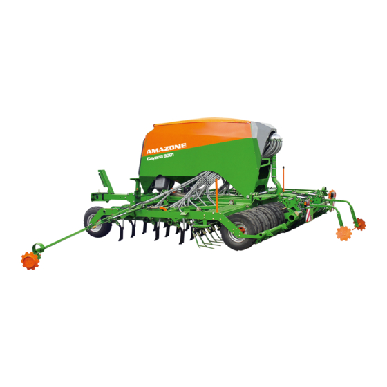
(2) Distributor head (6) Rear harrow (3) TineTeC tine coulters (7) Leading guide wheels (4) Exact harrow tines (8) Track marker (to close the seed furrow) (9) Tramline marker Cayena 6001/-C BAH0062-5 07.20... - Page 41 (4) Jack, foldable (5) Step (6) Mount with hose cabinet Fig. 13 (1) Roller tarpaulin for implements with a one-chamber system (2) Ascent with handle Fig. 14 Hopper cover for implements with two chamber system Fig. 15 Cayena 6001/-C BAH0062-5 07.20...
- Page 42 (2) Electric motor for the metering roller drive (3) Low level sensor Fig. 16 (1) Metering unit with sluice for implements with two chamber system Fig. 17 Fig. 18/... TineTeC tine coulters Fig. 18 Cayena 6001/-C BAH0062-5 07.20...
- Page 43 Product description Fig. 19/... Leading guide wheels Fig. 19 Fig. 20/... Tractor wheel mark eradicator Fig. 20 Fig. 21/... Cutting discs Fig. 21 Cayena 6001/-C BAH0062-5 07.20...
- Page 44 Product description Safety and protective equipment (1) Fan guard Fig. 22 Hopper guard Fig. 23 Mechanical lock for the implement sections during transport Fig. 24 Cayena 6001/-C BAH0062-5 07.20...
- Page 45 The function of the tractor control unit is represented symbolically: Latched, for a permanent oil circulation When the button is pressed, as long as the function is active Float position, free oil flow in the control unit Cayena 6001/-C BAH0062-5 07.20...
- Page 46 Pressureless return flow (red T) Fan hydraulic motor section 6.3, page 104 Important! Always connect this hydraulic line to the tractor. The connection of this hydraulic line to the tractor is required for all of the above-listed hydraulic functions. Cayena 6001/-C BAH0062-5 07.20...
-
Page 47: Transportation Equipment
(2) Reflector, red (3) Reflector, yellow (4) Number plate holder (5) Lighting for the number plate (6) Bracket for speed rating Fig. 27 (1) 2 forwards-facing warning signs (2) 2 forwards-facing marker lights Fig. 28 Cayena 6001/-C BAH0062-5 07.20... - Page 48 3 m Fig. 29 (1) 2 road safety bars to cover the rear harrow tines Fig. 30 Safety device against unauthorised use Lower link crosspiece with lockable safety device against unauthorised use. Fig. 31 Cayena 6001/-C BAH0062-5 07.20...
-
Page 49: Proper Use
adherence of inspection and maintenance work exclusive use of genuine AMAZONE spare parts. Other uses to those specified above are forbidden and shall be considered as improper. For any damage resulting from improper use ... -
Page 50: Danger Areas And Danger Points
when unfolding and folding the implement sections near overhead power lines in the area of moving parts underneath raised, unsecured implements or parts of implements. Cayena 6001/-C BAH0062-5 07.20... -
Page 51: Rating Plate And Ce Mark
(6) Perm. system pressure rear axle load (7) Perm. system pressure system pressure (8) Perm. system pressure total weight kg Fig. 32 (9) Factory (10) Model year CE mark Information on the CE mark: (1) Year of manufacture Fig. 33 Cayena 6001/-C BAH0062-5 07.20... - Page 52 Information on the EU rating plate: (1) Class, sub-class and speed class (2) EU type approval number (3) Vehicle identification number (4) Technically permissible total weight (5) Technically permissible drawbar load A0 (6) Technically permissible axle load A1 Fig. 34 Cayena 6001/-C BAH0062-5 07.20...
-
Page 53: Technical Data
6.1.1, page 98 Max. permitted speed see section 9, page 147 The following may not be exceeded during road transport the permissible total weight the permissible rear axle load the permissible drawbar load. Cayena 6001/-C BAH0062-5 07.20... -
Page 54: Required Tractor Equipment
The workplace-related emission value (acoustic pressure level) is 70 dB(A), measured in operating condition at the ear of the tractor driver with the cabin closed. Measuring unit: OPTAC SLM 5. The noise level is primarily dependent on the vehicle used. Cayena 6001/-C BAH0062-5 07.20... -
Page 55: Structure And Function
The track markers (Fig. 35/6) mark the field connection run in the centre of the tractor. Before germination of the seed, the tramline marker (Fig. 35/7) marks the tramlines. The implement can be folded to a transport width of 3 m. Cayena 6001/-C BAH0062-5 07.20... - Page 56 (green) in the tractor cab executes the selected hydraulic function. The changeover valve lever can assume one of the two positions: Valve lever up Valve lever down Folding the implement sections Folding the track marker Fig. 38 Fig. 37 Cayena 6001/-C BAH0062-5 07.20...
-
Page 57: Control Terminal For Implements With Isobus System
The ISOBUS system makes it possible to connect the implement to any ISOBUS control terminal. If the tractor has an ISOBUS system, the AMAZONE job computer can be connected to the existing ISOBUS socket of the tractor and operated with the on-board terminal. -
Page 58: Amazone Twinterminal
The job computer must be equipped with the AMAZONE Bluetooth adapter. Download the mySeeder app onto your mobile device from the Fig. 41 App Store or Play Store. -
Page 59: Parking Brake
Releasing the parking brake: Turn the crank to the left (L). Fig. 42 In the parking position, the crank (Fig. 43/1) is inserted in the transport bracket and secured with a linch pin (Fig. 43/2). Fig. 43 Cayena 6001/-C BAH0062-5 07.20... -
Page 60: Hydraulic Service Brake System
The implement can be equipped without a service brake system. Without a service brake system, the implement is not permitted in Germany, all EU countries and in several other countries. Before initial operation, check the officially approved registration of your implement without a service brake system. Cayena 6001/-C BAH0062-5 07.20... -
Page 61: Implement Documentation
(Fig. 45). Other sources are also possible, refer to the control terminal operating manual. The working speed data is used to determine: the worked area (hectare counter) the required speed for the speed of the metering roller(s). Fig. 45 Cayena 6001/-C BAH0062-5 07.20... - Page 62 For seed placement, the "on grip" tine coulters push into the soil. In this way the tine coulters, supported on the following wedge ring roller and the leading guide wheels, maintain the precise working depth. Fig. 47 Cayena 6001/-C BAH0062-5 07.20...
-
Page 63: Cutting Discs
The maximum working depth is achieved when no stops are in contact with the piston of the hydraulic cylinder. If all stops are in contact with the piston, the cutting discs do not work in the ground. Fig. 49 Cayena 6001/-C BAH0062-5 07.20... - Page 64 On loose soil, furrow ridges may form between the tyres. This can be remedied by the adjustable furrow ridge levellers which can be positioned at different points in a group of holes (Fig. 52/1). Fig. 52 Cayena 6001/-C BAH0062-5 07.20...
- Page 65 The hopper can selectively be equipped with one or two chambers. There is 1 metering unit under each chamber. 5.10.1 One chamber hopper The hopper with one chamber is closed using a roller tarpaulin (Fig. 54/1) to protect against dust and rain. Fig. 54 Cayena 6001/-C BAH0062-5 07.20...
- Page 66 When switching on the fan, pressure builds up in the hopper and conveyor section. The hopper cover seals the hopper pressure-tight. Fig. 56 The charging sieves serve to collect foreign objects when filling the chambers. Fig. 57 Cayena 6001/-C BAH0062-5 07.20...
- Page 67 Attach the sensor to the higher bracket. Fine seed types (e.g. rapeseed): Attach the sensor on the lower bracket (factory setting). Fertiliser: Attach the sensor to one of the two brackets, depending on the spread rate. Cayena 6001/-C BAH0062-5 07.20...
-
Page 68: Conveyor Section
2 sluices (Fig. 62/2) 1 single conveyor section (Fig. 62/3) 1 distributor head. The spread rate is calibrated consecutively on both metering units. The order of the numbered metering units can be freely selected. Fig. 62 Cayena 6001/-C BAH0062-5 07.20... - Page 69 The working speed is determined, e.g. by pulses from the radar or the tractor signal. can be increased during operation, e.g. when changing from normal to heavy soils, by pressing a button on the control terminal in defined quantity increments. Cayena 6001/-C BAH0062-5 07.20...
- Page 70 (Fig. 65/1) of the metering roller can be enlarged by repositioning the wheels and the plates. Fig. 65 The volume of some metering rollers can be modified by repositioning/removing the existing wheels and inserting metering wheels without chambers. Fig. 66 Cayena 6001/-C BAH0062-5 07.20...
- Page 71 Volume: ....7.5 cm For seed drills with one or two metering units and one distributor head Metering roller Volume: ....20 cm For seed drills with one or two metering units and one distributor head Cayena 6001/-C BAH0062-5 07.20...
- Page 72 Structure and function Metering roller Volume: ....40 cm Metering roller Volume: ....120 cm Metering roller Volume: ....210 cm Cayena 6001/-C BAH0062-5 07.20...
- Page 73 Structure and function Metering roller Volume: ....350 cm Metering roller Volume: ....600 cm Metering roller Volume: ....660 cm Metering roller Volume: ....880 cm Cayena 6001/-C BAH0062-5 07.20...
- Page 74 120 cm³ Seed Beans Buckwheat Spelt Peas Flax (dressed) Barley Grass seed Oats Millet Caraway Lupins Lucerne Maize Poppy Oilseed flax (moist dressing) Fodder radish Phacelia Rapeseed Red clover Mustard Soya Sunflowers Turnips Triticale Wheat Vetches Cayena 6001/-C BAH0062-5 07.20...
- Page 75 Lupins Lucerne Maize Poppy Oilseed flax (moist dressing) Fodder radish Phacelia Rapeseed Red clover Mustard Soya Sunflowers Turnips Triticale Wheat Vetches 5.12.2 Table – Fertiliser metering rollers Metering rollers 350 cm³ 660 cm³ Fertiliser Fertiliser (granular) Cayena 6001/-C BAH0062-5 07.20...
- Page 76 after replacing the metering roller if the hopper takes more/less time than expected to empty. The actual spread rate then does not correspond to the spread rate determined by calibration. Cayena 6001/-C BAH0062-5 07.20...
- Page 77 The arrow is pointing in the direction of travel of the implement. Lever position (1): closed Lever position (2): open Fig. 71 Cayena 6001/-C BAH0062-5 07.20...
- Page 78 The rear metering roller is switched off and the front metering roller is started automatically as soon as the seed level reaches the low level sensor in the rear chamber. Cayena 6001/-C BAH0062-5 07.20...
- Page 79 5.13.3 the tractor PTO shaft, see section 5.13.4. Fan suction guard screen Under very dry conditions, the fan suction guard screen prevents the suction of straw residues into the fan. Fig. 75 Cayena 6001/-C BAH0062-5 07.20...
- Page 80 (Fig. 76/2), e.g. rapeseed or grass seed grains or legumes (Fig. 76/3) and the application rate (Fig. 76/4). Example: Cayena 6001 grain application rate: 130 kg/ha (Fig. 76/4) Required fan speed: 3200 rpm. Cayena 6001/-C BAH0062-5 07.20...
- Page 81 grains or legumes (Fig. 77/5) and the spread rate (Fig. 77/6). Example: Cayena 6001-C fertiliser application rate: 150 kg/ha (Fig. 77/3) grain spread rate: 130 kg/ha (Fig. 77/6) Required fan speed: 3600 rpm. Cayena 6001/-C BAH0062-5 07.20...
- Page 82 Set the fan speed at the flow control valve of the tractor (see chapter 8.6.1) on the pressure relief valve of the hydraulic motor, see section 8.6.2, if the tractor has no flow control valve. Fig. 79 Cayena 6001/-C BAH0062-5 07.20...
- Page 83 Fig. 80 The hydraulic motor (Fig. 81/1) is fastened on the rear wall of the fan. Fig. 81 In a closed circuit, the implement carries the hydraulic fluid in an oil tank (Fig. 82/1). Fig. 82 Cayena 6001/-C BAH0062-5 07.20...
-
Page 84: Distributor Head
(Fig. 85/1). The seed tube monitoring does not react. There is no warning message. The warning message is only triggered if the if the seed line is blocked between the sensor and the air separator. Fig. 85 Cayena 6001/-C BAH0062-5 07.20... - Page 85 The notches (Fig. 87/3) are for the purpose of orientation for setting the planting depth. The maximum placement depth is 8 cm. Fig. 87 The working depth can be easily adjusted by means of the switchable ratchet spanner. Fig. 88 Cayena 6001/-C BAH0062-5 07.20...
-
Page 86: Exact Following Harrow Tine Position
The adjuster segments (Fig. 91) are used to adjust the position of the exact following harrow tines. The exact following harrow tines (Fig. 90/1) are correctly adjusted if they lie horizontally on the ground. have sufficient free downward travel. Fig. 91 Cayena 6001/-C BAH0062-5 07.20... -
Page 87: Exact Following Harrow Pressure
The rear harrow (Fig. 93/1) throws loose soil onto the compacted strips for an even surface appearance. The following are adjustable the angle at which the harrows penetrate the ground. the penetration depth of the harrows in the ground. Fig. 93 Cayena 6001/-C BAH0062-5 07.20... -
Page 88: Track Marker
After passing the obstacle, the tractor driver unfolds the track marker again by actuating the tractor control unit, and deactivates the obstacle function on the control terminal. Cayena 6001/-C BAH0062-5 07.20... - Page 89 The seed pre-metering is used e.g., when corners need to be seeded, which can only be reached by reversing the implement with the coulters lifted. The runtime of the seed pre-metering can be adjusted, refer to the "ISOBUS software" operating manual. Cayena 6001/-C BAH0062-5 07.20...
- Page 90 the seeding quantity is reduced. The reduced quantity can be adjusted, see "AmaDrill+" operating manual "ISOBUS software" operating manual. Factory settings The seed line tubes of the tramline coulters are marked. Cayena 6001/-C BAH0062-5 07.20...
- Page 91 The track width (a) of the tramline corresponds to that of the cultivating tractor and is adjustable. The wheelmark width (c) of the tramline increases with an increasing number of tramline coulters fitted next to each other. Cayena 6001/-C BAH0062-5 07.20...
-
Page 92: Tramline Rhythm, Tabular Determination
(working width of the fertiliser spreader) ............18 m Column C: Tramline rhythm ....................3 Column D: Tramline counter ....................2 The tramline counter for the first field pass can be found under the lettering "START". Cayena 6001/-C BAH0062-5 07.20... - Page 93 Structure and function Fig. 101 Cayena 6001/-C BAH0062-5 07.20...
-
Page 94: One-Sided Switching
The installation of an insert (Fig. 103/1) in the distributor head closes the outlets to the coulters of one implement half. Halve the spread rate on the control terminal when working with half the working width. Fig. 103 Cayena 6001/-C BAH0062-5 07.20... -
Page 95: Tramline Marker
When transporting the implement, the sections of the tramline marker are folded, fastened with pins, and secured with linch pins. 5.21 Work floodlights The work floodlights allow visibility of the worked area, even in the dark. Cayena 6001/-C BAH0062-5 07.20... -
Page 96: Initial Operation
This does not apply to equipment movements that: are continuous or are automatically locked or require a float position or pressure position due to their function. Cayena 6001/-C BAH0062-5 07.20... -
Page 97: Checking The Suitability Of The Tractor
25 km/h. In Russia, for example, the maximum permissible forward speed is 10 km/h. Before initial operation, check the officially approved registration of your implement without its own service brake system. Cayena 6001/-C BAH0062-5 07.20... - Page 98 § 70 of the German Regulations Authorising the Use of Vehicles for Road Traffic and the required approval according to § 29, paragraph 3 of the German Road Traffic Regulations. Cayena 6001/-C BAH0062-5 07.20...
- Page 99 [m] Tractor wheel base See tractor operating manual or vehicle documents or measurement [m] Distance between the centre of the rear See tractor operating manual or vehicle axle and the centre of the lower link hitch documents or measurement Cayena 6001/-C BAH0062-5 07.20...
- Page 100 (section 6.1.1.7). 6.1.1.6 Load-bearing capacity of the tractor tyres In the table (section 6.1.1.7), enter the double value (2 tyres) of the permissible tyre load-bearing capacity (see e.g. tyre manufacturer's documentation). Cayena 6001/-C BAH0062-5 07.20...
- Page 101 (if necessary) attached to the tractor for the required minimum front ballast (G V min You must use a front weight that is equal to at least the required minimum front ballast (G V min Cayena 6001/-C BAH0062-5 07.20...
- Page 102 that the permissible total weight of the tractor is complied with that the approved load capacities of the tractor tyres are not exceeded. Cayena 6001/-C BAH0062-5 07.20...
-
Page 103: Secure The Tractor / Implement Against Unintentional Starting And Rolling Away
if moving parts are not blocked against unintentional movement. Coming in to contact with unsecured components poses a hazard during this kind of work in particular. Cayena 6001/-C BAH0062-5 07.20... - Page 104 The capacity of the tractor's oil tank (Fig. 106/4) should be at least twice the oil flow rate. If the hydraulic fluid heats up excessively, the installation of an oil cooler is required at a specialist workshop. Cayena 6001/-C BAH0062-5 07.20...
-
Page 105: Coupling And Uncoupling The Implement
Risk of contusions, catching, and knocks when the implement unexpectedly releases from the tractor! Check the tensioned crosspiece and the drawbar for visible defects whenever the implement is coupled. Have any visible defects fixed without delay in a specialist workshop. Cayena 6001/-C BAH0062-5 07.20... - Page 106 For this reason, the implement must be connected to the lower links of the tractor and the parking brake of the implement and tractor must be applied before the supply line (red) is connected. Only then can the wheel chocks be removed. Cayena 6001/-C BAH0062-5 07.20...
- Page 107 (red) is connected. The brake is not released if the implement's parking brake is applied. To make sure that the implement is braked after uncoupling, apply the implement's parking brake beforehand. Only release the parking brake once the implement has been coupled up to the tractor. Cayena 6001/-C BAH0062-5 07.20...
- Page 108 108/2) on the tractor, in accordance with regulations. 8. Fasten the couling head of the supply line (red) in the coupling marked red on the tractor, in accordance with regulations. Fig. 108 9. Remove wheel chocks. 10. Release the implement parking brake. Cayena 6001/-C BAH0062-5 07.20...
- Page 109 1. Secure the implement with wheel chocks (Fig. 109). Fig. 109 2. Apply the implement's parking brake. Fig. 110 Cayena 6001/-C BAH0062-5 07.20...
- Page 110 (emergency brake) is inactive. With a full compressed air tank, the Fig. 112 brakes are released immediately when the supply line (red) is connected to the tractor. The button (Fig. 112/1) can then no longer be moved. Cayena 6001/-C BAH0062-5 07.20...
-
Page 111: Coupling The Hydraulic Service Brake System
10 seconds with the engine running. This fills the hydraulic accumulator. When the hydraulic accumulator is full, the implement's service brake system responds when the tractor brake pedal or the tractor parking brake is applied. Cayena 6001/-C BAH0062-5 07.20... - Page 112 Fig. 115 8. Apply the tractor parking brake, switch off the tractor engine, and remove the ignition key. 9. Remove wheel chocks. 10. Release the implement parking brake. Cayena 6001/-C BAH0062-5 07.20...
-
Page 113: Uncoupling The Hydraulic Service Brake System
Before uncoupling the implement from the tractor, secure it with 2 wheel chocks and apply the implements parking brake. 1. Secure the implement with wheel chocks (Fig. 116). Fig. 116 2. Apply the implement's parking brake. Fig. 117 Cayena 6001/-C BAH0062-5 07.20... - Page 114 5. Plug the hydraulic socket into the protective cap (Fig. 119/1). The protective cap is secured to the hose cabinet and protects the socket against soiling in the parking position. Fig. 119 Cayena 6001/-C BAH0062-5 07.20...
-
Page 115: Coupling The Hydraulic Hose Lines
Push the hydraulic plug(s) into the hydraulic socket(s) until the hydraulic plug(s) perceivably lock(s). Check the coupling points of the hydraulic hose lines for proper fit and sealing. Cayena 6001/-C BAH0062-5 07.20... -
Page 116: Uncoupling The Hydraulic Hose Lines
Supply lines between the tractor and the implement". Fig. 120 7.3.2 Uncoupling the hydraulic hose lines 1. Put the tractor control units into the float position. 2. Disconnect the hydraulic plug and hang it in the hose cabinet. Fig. 121 Cayena 6001/-C BAH0062-5 07.20... - Page 117 CAUTION Only connect the implement when the tractor and implement are coupled the tractor parking brake is applied the tractor engine is switched off and the ignition spanner has been removed. Cayena 6001/-C BAH0062-5 07.20...
- Page 118 The job computer may fail if LED floodlights other than those listed in the spare parts list are used in the event of repairs the lighting system is equipped with more than two LED floodlights. Cayena 6001/-C BAH0062-5 07.20...
- Page 119 Design of the ball sleeve with collecting tray, see the tractor operating manual. 4. Secure each ball sleeve with a linch pin. CAUTION Danger of getting crushed in the area of the moving tensioned Fig. 125 crosspiece. Cayena 6001/-C BAH0062-5 07.20...
- Page 120 13. Raise the tractor's lower link until the jack comes free of the ground. 14. Remove the pin (Fig. 126/1). Fig. 126 15. Fold up the jack, locate it with the pin (Fig. 127/1) and secure with the linch pin. Fig. 127 Cayena 6001/-C BAH0062-5 07.20...
- Page 121 16. Push the wheel chocks into the holders and secure. Fig. 129 17. Release the parking brake of the implement. 18. Before moving off: Check the function of the brake and lighting system Carry out a brake test. Fig. 130 Cayena 6001/-C BAH0062-5 07.20...
-
Page 122: Uncoupling The Implement
the tractor engine is switched off the ignition key has been removed the implement is secured with two wheel chocks the implement parking brake is applied. Cayena 6001/-C BAH0062-5 07.20... - Page 123 8. Switch off the tractor PTO shaft, apply the tractor parking brake, switch off the tractor engine, and remove the ignition key. 9. Secure the implement with 2 wheel chocks. Fig. 132 10. Apply the implement's parking brake. Fig. 133 Cayena 6001/-C BAH0062-5 07.20...
- Page 124 Only couple/uncouple the hydraulic pump and tractor PTO shaft if the tractor and implement are secured to prevent unintentional start-up and rolling away. WARNING Hot components can cause burns. Wear gloves. Cayena 6001/-C BAH0062-5 07.20...
- Page 125 2. Switch off the tractor PTO shaft, apply the tractor parking brake, switch off the tractor engine, and remove the ignition key. Wait until the PTO shaft stops moving. 3. Remove the hydraulic pump (Fig. 137/1) from the tractor's PTO shaft and insert it in the mount. Fig. 137 Cayena 6001/-C BAH0062-5 07.20...
- Page 126 3. Adjust the wheel mark eradicator vertically, fix with the pin and secure with a linch pin (Fig. 138/4). Fig. 138 Only use the supplied wedge coulters (Fig. 138/5). Wedge coulters prevent damage to the tractor rear window due to projected stones. Cayena 6001/-C BAH0062-5 07.20...
- Page 127 7. Carry out the same settings on all adjuster segments. 8. Retract the integrated running gear The implement is lowered. The pistons of the hydraulic cylinder come into contact with the stops. Fig. 141 Cayena 6001/-C BAH0062-5 07.20...
- Page 128 The metering roller can be replaced more easily if the hopper is empty. 1. Close the opening between the hopper and the metering unit (only necessary when the hopper is full). 1.1 Remove the spanner (Fig. 143/1) from the holder. Fig. 143 Cayena 6001/-C BAH0062-5 07.20...
- Page 129 1.4 Slide the trough into the holder under the metering unit and open the flap. The design of the flap depends on the implement type. Fig. 146 2. Loosen the 2 bolts (Fig. 147/1). Fig. 147 Cayena 6001/-C BAH0062-5 07.20...
- Page 130 4. Pull out the metering roller (Fig. 150/1). Install the metering roller in the reverse sequence. Fig. 150 Secure the shutter (Fig. 151/1) in the parking position. Close the opening under the metering unit Secure the trough in the transport bracket. Fig. 151 Cayena 6001/-C BAH0062-5 07.20...
- Page 131 The trough is inserted in the transport bracket and is secured with a linch pin (Fig. 152/1). Fig. 152 8.5.1 Calibration methods - Overview Number Calibrating the spread rate Distributor Metering unit Chapter Page heads Cayena 6001 8.5.2 Cayena 6001-C 8.5.3 Cayena 6001/-C BAH0062-5 07.20...
- Page 132 "AmaDrill+" operating manual the "ISOBUS software" operating manual until the desired rate has been spread. 5. Close the injector sluice. 6.Insert the trough in the transport bracket and secure it with a linch pin. Cayena 6001/-C BAH0062-5 07.20...
- Page 133 the "AMADRILL+" operating manual the "ISOBUS software" operating manual until the desired rate has been spread. 6. Close the sluice. 7.Insert the trough in the transport bracket and secure it with a linch pin. Cayena 6001/-C BAH0062-5 07.20...
-
Page 134: Adjusting The Fan Speed
The pressure relief valve of the fan can be installed in 2 versions with round outer contour (Fig. 157/1) with hexagonal outer contour (Fig. 158/1). The setting of the fan speed depends on the version of the pressure relief valve. Cayena 6001/-C BAH0062-5 07.20... - Page 135 4. Set the fan speed during operation by adjusting the tractor PTO shaft speed. Do not exceed the following speeds: max. 1000 rpm PTO shaft speed max. 4000 rpm fan speed. The control terminal displays the fan speed. Fig. 159 Cayena 6001/-C BAH0062-5 07.20...
-
Page 136: Pressure Relief Valve With Round Outer Contour
160/1). Do not exceed the maximum fan speed of 4000 rpm. Fan speed Turning to the right: increases the nominal fan speed Turning to the left: reduces the nominal fan speed 3. Tighten the lock nut. Cayena 6001/-C BAH0062-5 07.20... -
Page 137: Pressure Relief Valve With Hexagonal Outer Contour
162/1). Do not exceed the maximum fan speed of 4000 rpm. Fan speed Turning to the right: increases the nominal fan speed Turning to the left: reduces the nominal fan speed 3. Tighten the lock nut. Cayena 6001/-C BAH0062-5 07.20... - Page 138 1 (front) and 2 (rear). The pressure difference must not be greater than 5 mbar. If the required air pressure is not reached, check the system for leaks. Amongst other things, Fig. 164 check if the hopper cover is closed. Cayena 6001/-C BAH0062-5 07.20...
- Page 139 Repeat the procedure as described. Always perform the same settings on both adjusting segments. Lock each setting using the linch pin (Fig. 166/1). The ratchet is reset by actuating the lever (Fig. 166/2). Fig. 166 Cayena 6001/-C BAH0062-5 07.20...
- Page 140 3. Relieve the lever. 4. Secure the bolt with a spring cotter pin. 5. Apply the same setting to all adjuster segments. Fig. 168 The extension is kept in the transport bracket (Fig. 169/1) Fig. 169 Cayena 6001/-C BAH0062-5 07.20...
-
Page 141: Adjusting The Rear Harrow
2. Adjust the penetration depth of the harrows in the ground. 2.1 Adjustments are made by repositioning the pin (Fig. 171/3) in the group of holes (Fig. 171/4) and securing with a linch pin. Fig. 171 Cayena 6001/-C BAH0062-5 07.20... - Page 142 10. Tighten the bolts (Fig. 172/2). Fig. 172 The table values indicate the distance "A" from the centre of the implement to the contact area of the track marker disc. Implement Distance "A" working widths 6.0 m 6.0 m Fig. 173 Cayena 6001/-C BAH0062-5 07.20...
- Page 143 2. Halve the spread rate, see "AmaDrill+" operating manual "ISOBUS software" operating manual. Fig. 174 Remove the insert and set the full seeding rate before commencing the next run. Cayena 6001/-C BAH0062-5 07.20...
- Page 144 "on grip" on heavy soils. Fig. 176 8.12.2 Moving the tramline marker into transport position Locate the track disc carrier in the transport position with a pin (Fig. 177/1) and secure it with a linch pin. Fig. 177 Cayena 6001/-C BAH0062-5 07.20...
- Page 145 (Fig. 179/1) and secure them with spring holders. Fig. 179 5. The spring holders (Fig. 180/1) are used to fasten the road safety bars (Fig. 180/2). Fig. 180 Cayena 6001/-C BAH0062-5 07.20...
-
Page 146: Moving The Road Safety Bar Into Parking Position
Settings 8.13.2 Moving the road safety bar into parking position 1. Place the road safety bars (Fig. 181/1) inside each other, lay them in the transport bracket and secure with spring holders. Fig. 181 Cayena 6001/-C BAH0062-5 07.20... - Page 147 ....................Page 145 13. Check the lighting system and warning signs for proper function and cleanliness ........................... Page 47 14. Disable the tractor control units, see tractor operating manual Cayena 6001/-C BAH0062-5 07.20...
- Page 148 The permissible total weight can be found on the rating plate of your implement. Running gear with polyurethane-filled tyres The running gear can be equipped with polyurethane-filled tyres. Tyres filled with polyurethane may require an operating permit. Ask your service partner about the legal guidelines. Cayena 6001/-C BAH0062-5 07.20...
-
Page 149: Maximum Permissible Speed
Before initial operation, check the officially approved registration of your implement without its own service brake system. Maximum Implement equipment permissible speed 25 km/h Implements without service brake system. In Russia, the maximum permissible speed is 10 km/h for implements without 10 km/h their own service brake system. Cayena 6001/-C BAH0062-5 07.20... - Page 150 These risks pose serious injuries or death. Comply with the maximum load of the mounted / towed implement and the approved axle and drawbar loads of the tractor. Cayena 6001/-C BAH0062-5 07.20...
- Page 151 Transportation without a correctly fitted road safety bar is forbidden. In bends take into consideration the wide sweep and the centrifugal mass of the implement. Cayena 6001/-C BAH0062-5 07.20...
-
Page 152: Use Of The Implement
Stay at a safe distance from the driven PTO shaft. Before switching on, check to ensure that the tractor PTO shaft speed corresponds to the permitted drive speed of the implement. Shut down the tractor engine immediately in case of danger. Cayena 6001/-C BAH0062-5 07.20... - Page 153 WARNING Before performing adjustment, maintenance and repair work, Read and observe Section "Secure the tractor / implement against unintentional starting and rolling away", page 103. Section "Safety information for users", page 28. Cayena 6001/-C BAH0062-5 07.20...
- Page 154 The power cable is inserted in 3-pin standard socket in the tractor cab. When transporting the implement on public roads, switch off the work floodlights. The connection of additional or non-approved floodlights can lead to complete failure of the ISOBUS job computer and warranty loss. Cayena 6001/-C BAH0062-5 07.20...
- Page 155 7. Check all implement settings ................... Page 126 8. Run the fan up to nominal speed ..................Page 134 9. Check the tramline counter, correct if necessary ............Page 93 10. Start driving and then check the placement depth ............Page 167 Cayena 6001/-C BAH0062-5 07.20...
- Page 156 The valve switches to fold in the implement sections. Fig. 185 3. Release the mechanical lock. 3.1 Pull the locking mechanism (Fig. 186/1) forward until it is released from the locking device (Fig. 186/2). Fig. 186 Cayena 6001/-C BAH0062-5 07.20...
- Page 157 The valve switches to actuate the track markers. 10. Actuate the control unit (yellow). Lower the implement into working position using the integrated running gear. Pull the implement forward slightly, immediately before lowering the tools into the ground. Fig. 190 Cayena 6001/-C BAH0062-5 07.20...
- Page 158 5. Fully raise the implement. 5.1 Actuate the control unit (yellow) until the integrated running gear is extended. 6. Apply the tractor parking brake. Fig. 192 7. Actuate the control unit (green) until the implement sections are folded. Fig. 193 Cayena 6001/-C BAH0062-5 07.20...
- Page 159 8. Align the implement horizontally. 8.1 Actuate the control unit (yellow). 8.2 Lower the implement via the integrated running gear until the implement is horizontal. Ensure that the implement has sufficient ground clearance in all driving situations. Fig. 195 Cayena 6001/-C BAH0062-5 07.20...
- Page 160 (yellow). Lift the implement using the running gear until the acoustic signal is heard. Fig. 197 3.3 Apply the tractor parking brake. 3.4 Unfold the implement sections. Fig. 198 Cayena 6001/-C BAH0062-5 07.20...
- Page 161 (yellow). Fig. 200 Fold both track markers (parking position). Lift the implement using the running gear until the acoustic signal is heard. 2.3 Apply the tractor parking brake. Cayena 6001/-C BAH0062-5 07.20...
- Page 162 3. Align the implement horizontally. 3.1 Actuate the control unit (yellow). 3.2 Lower the implement via the integrated running gear until the implement is horizontal. Ensure that the implement has sufficient ground clearance in all driving situations. Fig. 203 Cayena 6001/-C BAH0062-5 07.20...
-
Page 163: Filling The Hopper
Should the control part trip an alarm if the theoretically calculated residual amount is reached in the hopper, enter the filling quantity [kg] on the control terminal log off the low level sensor of the implement on the control terminal. Cayena 6001/-C BAH0062-5 07.20... - Page 164 The belt (Fig. 206/2) serves to open and close the roller tarpaulin. Fig. 206 12. Slowly pull the strap out of the strap holder. The roller tarpaulin opens as the strap is released. Fig. 207 Cayena 6001/-C BAH0062-5 07.20...
- Page 165 DANGER Hold on to the handle bars of the hopper cover when climbing onto the sieves. Do not climb onto the sieve if the hopper is full and the transported material covers the sieve. Fig. 210 Cayena 6001/-C BAH0062-5 07.20...
- Page 166 2.2 Close the hopper cover. The handle (Fig. 211/2) is used to close the hopper cover. 2.3 Remove the spring-loaded pin (Fig. 212/1) and swivel the lever (Fig. 212/2) downwards. Fig. 212 2.4 Unlock the lever. Fig. 213 Cayena 6001/-C BAH0062-5 07.20...
-
Page 167: During Operation
1. Spread seed for approx. 100 m at working speed on the field. Drive ca. 100 m at working speed. 2. Expose the seed at a number of points, including the area of the outside coulters. 3. Check the seed placement depth. Cayena 6001/-C BAH0062-5 07.20... - Page 168 4. After turning, actuate the control unit (yellow) for at least 10 seconds so that all hydraulic functions can be carried out completely. 5. Start the field pass when the tools penetrate into the soil. Cayena 6001/-C BAH0062-5 07.20...
-
Page 169: End Of Work On The Field
Disconnect the implement plug (e.g. ISOBUS plug). Risk of accident due to unintentional activation of the metering unit or other implement components caused by radar pulses. Cayena 6001/-C BAH0062-5 07.20... - Page 170 Fig. 217 Reassembly 3. Thoroughly clean the metering unit and the metering roller. 4. Reassemble in the reverse order, see section 8.4, 128. 5. Repeat the process if the implement has two metering units. Cayena 6001/-C BAH0062-5 07.20...
- Page 171 A visual and acoustic warning is given when the residual quantity in the hopper is undercut (when the fill level sensor is correctly set). The residual quantity should be large enough to prevent fluctuations in the spread rate. Cayena 6001/-C BAH0062-5 07.20...
-
Page 172: Fault Table
Oil quantity Set the oil volume too high or too low Fan sensor defective Replace the fan sensor Tramline control shutters in the Distributor head is soiled Clean distributor distributor head not working head with control disc Cayena 6001/-C BAH0062-5 07.20... -
Page 173: Maintenance And Repairs
Every 2 weeks Section 12.5.5 Check the tyre inflation pressure of the leading guide wheels Section 12.5.6 Check the inflation pressure of the wedge ring tyres Check the on-board hydraulic system (oil quantity and oil filter) Section 12.5.7 Cayena 6001/-C BAH0062-5 07.20... - Page 174 Check the pressure in the compressed air tank workshop Specialist Section 12.7.7.3 Leak tightness check workshop Specialist Section 12.7.7.4 Cleaning the line filter workshop Every 12 months Specialist Check the service brake system (all versions) Section 12.7.6 workshop for operational safety Cayena 6001/-C BAH0062-5 07.20...
- Page 175 25 h Fig. 224/3 25 h Fig. 225/1 25 h Fig. 225/2 25 h Fig. 226/1 25 h Fig. 227/1 25 h Axle, braked Fig. 228/1 200 h Axle, unbraked Fig. 219 Fig. 220 Fig. 221 Cayena 6001/-C BAH0062-5 07.20...
- Page 176 Maintenance and repairs Fig. 222 Fig. 223 Fig. 224 Fig. 225 Fig. 226 Fig. 227 Fig. 228 Cayena 6001/-C BAH0062-5 07.20...
- Page 177 Disconnect the implement plug (e.g. ISOBUS plug). Risk of accident due to unintentional activation of the metering unit or other implement components caused by radar pulses. Cayena 6001/-C BAH0062-5 07.20...
- Page 178 12.3.1 Securing the connected implement Before working on the implement, place the implement connected to the tractor on the jack to prevent unintentional lowering of the tractor's lower link. Fig. 229 Cayena 6001/-C BAH0062-5 07.20...
- Page 179 Wear protective clothing, breathing mask, safety glasses and gloves when filling the implement when emptying the hopper and metering unit when removing dressing dust when working on the distributor head. Cayena 6001/-C BAH0062-5 07.20...
- Page 180 Safety when working on the hydraulic system Only a specialist workshop may perform work on the hydraulic system. 12.3.5 Safety when working on the service brake system Only a specialist workshop may perform work on the service brake system. Cayena 6001/-C BAH0062-5 07.20...
-
Page 181: Visual Inspections
If the visual inspection, function or action testing of the service brake system shows any signs of deficiencies, have a thorough inspection of all components performed immediately at a specialist workshop. DANGER Only specialist workshops may perform adjustment and repair work on the service brake system. Cayena 6001/-C BAH0062-5 07.20... - Page 182 Have any defects on the hydraulic hose lines immediately repaired by a specialist workshop. Use only original AMAZONE hydraulic hose lines. Have the hydraulic hose lines checked for proper functioning by a specialist workshop at least every quarter.
- Page 183 PTO shaft, is equipped with an oil cooler. Clean the spaces between the fins of the oil cooler with compressed air. Clean the oil cooler once a day, with intensive soiling, several times a day. Fig. 234 Cayena 6001/-C BAH0062-5 07.20...
- Page 184 (Fig. 237/A) with compressed air. 5. Install the plastic cap (Fig. 237/2). 6. Fix the plastic cap with winged nuts (Fig. 237/1). Fig. 237 Intensive cleaning requires the shutters to be removed, see section 12.7.4.1, page 192. Cayena 6001/-C BAH0062-5 07.20...
- Page 185 The running gear (Fig. 240/1) can be equipped with polyurethane-filled tyres, which do not need to be checked for inflation pressure. Polyurethane-filled tyres must only be used on the running gear (Fig. 240/1), due to their operating weight. Fig. 240 Cayena 6001/-C BAH0062-5 07.20...
- Page 186 Hydraulic fluid HLP68, DIN 51524-2, ISO 68 Fig. 242 There is no need to change the oil. Fig. 243/ to empty the oil filling plug ( 1) serves tank. Collect the escaping oil in a tray. Fig. 243 Cayena 6001/-C BAH0062-5 07.20...
- Page 187 Replace the oil filter (Fig. 245/1) with a new oil filter. Loosen the two hexagonal bolts 6 x 25 (Fig. 245/2). Pull the oil filter out of the oil tank and replace. Collect the escaping oil in a tray. Fig. 245 Cayena 6001/-C BAH0062-5 07.20...
-
Page 188: Installations
Shutdown of the implement over a long period of time Before parking the implement for a longer period of time Thoroughly clean and dry the coulters The coulters must be protected against rust with an environmentally-friendly anti-corrosion agent. Cayena 6001/-C BAH0062-5 07.20... - Page 189 Do not extend the drawbar pipe further from the implement frame than required. 12.7.2 Checking the tightening torques of the wheel and hub screws Bolt Tightening torque Wheel bolt 325 Nm M18 x 1.5 Bolt 450 Nm M16x1.5 Fig. 248 Cayena 6001/-C BAH0062-5 07.20...
- Page 190 (Fig. 250/1). If necessary, interchange the seed line tubes. Fig. 250 Adjust the track discs of the tramline marker (if fitted) to the new track width. Cayena 6001/-C BAH0062-5 07.20...
- Page 191 12.7.4.1, page 192. Deactivated shutters (Fig. 252/1) do not close the feed lines to the tramline coulters. Always activate or deactivate pairs of shutters positioned opposite each other on the base plate. Fig. 252 Cayena 6001/-C BAH0062-5 07.20...
- Page 192 9. The spigot of the shutter (Fig. 254/2) is inserted in the hole (Fig. 254/4). Fig. 254 10. Screw the shutter tunnel onto the base plate. 11. Install the outer distributor cover (Fig. 253/1), as described above. 12. Check the functioning of tramline control. Cayena 6001/-C BAH0062-5 07.20...
-
Page 193: Checking The Hydraulic Hose Lines
Corrosion of valve chest, reducing the function and strength rating. Installation requirements not complied with. Life span of 6 years has been exceeded, see section 12.4.3.1. DANGER Observe section "Safety when working on hydraulic hose lines", page 194. Cayena 6001/-C BAH0062-5 07.20... - Page 194 When installing or removing hydraulic hose lines, observe the following safety instructions: Only a specialist workshop may perform work on the hydraulic system. Use only genuine AMAZONE hydraulic hose lines! Ensure cleanliness. As a matter of principle, you must install the hydraulic hose lines such that, in all implement situations, ...
- Page 195 If the rating plate (Fig. 255/2) is rusty, loose or the rating plate is missing from the compressed air tank: replace the compressed air tank. Fig. 255 The compressed air tank may be replaced in a specialist workshop only. Cayena 6001/-C BAH0062-5 07.20...
- Page 196 1. Uncouple both coupling heads from the tractor, see section 7.1.2, page 109. 2. Clean both filters. 21. Unscrew the line from the coupling head. 2.2 To clean the filter, blow through using compressed air. Fig. 256 Cayena 6001/-C BAH0062-5 07.20...
-
Page 197: Oils And Greases
(Fig. 257). Carefully clean the grease nipple and grease gun before lubrication so that no dirt is pressed into the bearings. Press the dirty grease completely into the bearings and replace it with new grease. Fig. 257 Cayena 6001/-C BAH0062-5 07.20... -
Page 198: Bolt Tightening Torques
M 24x2 1100 1300 M 27 1050 1500 1800 M 27x2 1150 1600 1950 M 30 1450 2000 2400 M 30x2 1600 2250 2700 Tightening torques for rustproof bolts (inserted with assembly paste) 20.6 40.7 70.5 Cayena 6001/-C BAH0062-5 07.20... - Page 199 Maintenance and repairs Cayena 6001/-C BAH0062-5 07.20...
-
Page 200: Hydraulic Diagram
Hydraulic diagram Hydraulic diagram 13.1 Hydraulic diagram Cayena 6001 with AMADRILL+ Fig. 258/.. Description Fig. 258/.. Description 0010 Hydraulic system 0700 Track marker (with AMADRILL+) 0140 Throttle lift-out 0800 Pre-emergence marker 0150 Lift-out, right 0810 PEM valve 0160 Lift-out, left... - Page 201 Hydraulic diagram Fig. 258 Cayena 6001/-C BAH0062-5 07.20...
- Page 202 Hydraulic diagram 13.2 Hydraulic diagram - Cayena 6001(-C) with ISOBUS system Fig. 259/.. Description Fig. 259/.. Description 0010 Tractor hydraulics 0600 Track marker 0140 Throttle lift-out 0830 PEM, right 0150 Lift-out, right 0900 Cutting disc 0160 Lift-out, left 0910 Adjustment of left-hand cutting discs...
- Page 203 Hydraulic diagram Fig. 259 Cayena 6001/-C BAH0062-5 07.20...
- Page 206 H. DREYER GmbH & Co. KG Postfach 51 Tel.: + 49 (0) 5405 501-0 D-49202 Hasbergen-Gaste email: amazone@amazone.de Germany http:// www.amazone.de...
Need help?
Do you have a question about the Cayena 6001 and is the answer not in the manual?
Questions and answers