Moxa Technologies UC-8200 Series Hardware User Manual
Hide thumbs
Also See for UC-8200 Series:
- Hardware user manual (23 pages) ,
- Quick installation manual (14 pages)

Related Manuals for Moxa Technologies UC-8200 Series


Summary of Contents for Moxa Technologies UC-8200 Series
- Page 1 UC-8200 Series Hardware User’s Manual Edition 1.0, February 2019 www.moxa.com/product © 2019 Moxa Inc. All rights reserved.
- Page 2 UC-8200 Series Hardware User’s Manual The software described in this manual is furnished under a license agreement and may be used only in accordance with the terms of that agreement. Copyright Notice © 2019 Moxa Inc. All rights reserved. Trademarks The MOXA logo is a registered trademark of Moxa Inc.
-
Page 3: Table Of Contents
Table of Contents Introduction ............................1-1 Model Descriptions ..........................1-2 Package Checklist ..........................1-2 Product Features ..........................1-2 Product Specifications ......................... 1-2 Hardware Introduction ........................2-1 Appearance ............................2-2 UC-8210 Series ........................... 2-2 UC-8220 Series ........................... 2-4 Dimensions ............................2-5 LED Indicators ........................... -
Page 4: Introduction
Introduction The UC-8200 computing platform is designed for embedded data-acquisition applications. The UC-8200 platform comes with two RS-232/422/485 serial ports and dual 10/100/1000 Mbps Ethernet LAN ports, as well as a Mini PCIe socket to support cellular and Wi-Fi modules. These versatile communication capabilities let users efficiently adapt the UC-8200 to a variety of complex communications solutions. -
Page 5: Model Descriptions
UC-8200 Series Hardware Introduction Model Descriptions The UC-8200 Series includes the following models: • UC-8210-T-LX: Industrial computing platform with 2 serial ports, 2 Ethernet ports, 1 CAN port, USB, micro SD socket, -40 to 85°C operating temperature range • UC-8210-T-LX-S:Industrial computing platform with 2 serial ports, 2 Ethernet ports, 1 CAN port, TPM, USB, micro SD socket, -40 to 85°C operating temperature range... -
Page 6: Hardware Introduction
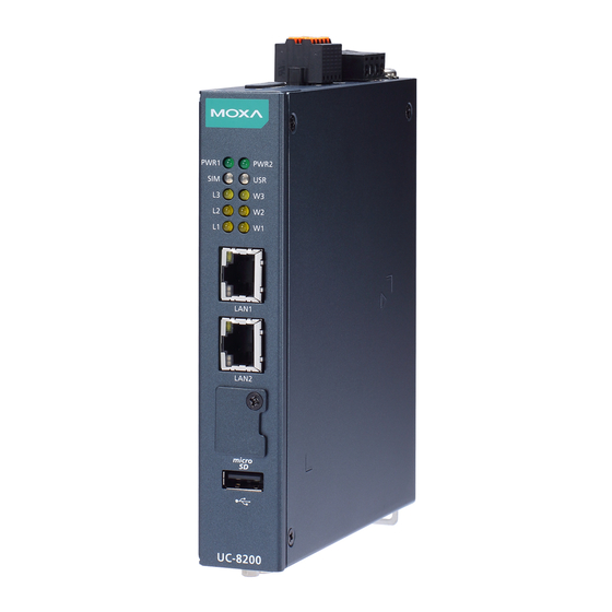
The LED indicators allow you to monitor device performance and quickly identify issues, and the multiple ports can be used to connect a variety of devices. The UC-8200 Series comes with a reliable and stable hardware platform that lets you devote the bulk of your time to application development. In this chapter, we provide basic information about the embedded computer’s hardware and its various components. -
Page 7: Appearance
UC-8200 Series Hardware Hardware Introduction Appearance UC-8210 Series Top Panel View Front Panel View... - Page 8 UC-8200 Series Hardware Hardware Introduction Bottom Panel View...
-
Page 9: Uc-8220 Series
UC-8200 Series Hardware Hardware Introduction UC-8220 Series Front Panel View... -
Page 10: Dimensions
UC-8200 Series Hardware Hardware Introduction Bottom Panel View Dimensions Unit: mm (in) UC-8210 Series... - Page 11 UC-8200 Series Hardware Hardware Introduction UC-8220 Series...
-
Page 12: Led Indicators
UC-8200 Series Hardware Hardware Introduction LED Indicators The function of each LED is described in the table below: LED Name Color Function Green Steady On USB device is connected and working normally. USB device is not connected. micro SD Green Steady On SD Card inserted and working normally. -
Page 13: Installation Options
UC-8200 Series Hardware Hardware Introduction Installation Options DIN-rail Mounting The aluminum DIN-rail attachment plate is already attached to the product’s casing. To mount the UC-8200 on to a DIN rail, make sure that the stiff metal spring is facing upwards and follow these steps. -
Page 14: Optional Wall Mounting
UC-8200 Series Hardware Hardware Introduction Optional Wall Mounting The UC-8200 Series can be mounted on to a wall using a wall-mounting kit as shown in the following illustrations. Step 1 Step 2 Use four screws to fasten the wall-mounting Use another four screws to mount the computer on brackets on the left panel of the computer. -
Page 15: Hardware Connection Description
Hardware Connection Description In this chapter, we describe how to connect the UC-8200 to a network and various devices. The following topics are covered in this chapter: Wiring Requirements Connecting the Power Grounding the Unit Connecting to the Network ... -
Page 16: Wiring Requirements
Connecting the Power Terminal Block Connect the power jack (in the package) to the UC-8200 Series’ DC terminal block (located on the top panel), and then connect the power adapter. It takes about 30 seconds for the system to boot up. Once the system is ready, the Power LED will light up. -
Page 17: Connecting To The Network
Connecting to a USB Device The UC-8200 Series computers come with a USB port located at the lower part of the front panel, allowing users to connect to a device with an USB interface. The USB port uses a type A connector. By default, the USB storage is mounted at /mnt/usbstorage. -
Page 18: Connecting To The Console Port
UC-8200 Series Hardware Hardware Connection Description Connecting to the Console Port The console port is an RS-232 port located on the top panel, and can be connected to with a 4-pin pin header cable. You can use this port for debugging or firmware upgrade. -
Page 19: Inserting The Sim Card
Connecting the Antennas There are two cellular antenna connectors (C1 and C2) on the front panel of the UC-8200 Series. Also a GPS connector is for the GPS module. All three connectors are of SMA type. Connect the antennas on these connectors. -
Page 20: Regulatory Approval Statements
Regulatory Approval Statements This device complies with part 15 of the FCC Rules. Operation is subject to the following two conditions: (1) This device may not cause harmful interference, and (2) this device must accept any interference received, including interference that may cause undesired operation. - Page 21 Federal Communications Commission (FCC) Statement 15.21 You are cautioned that changes or modifications not expressly approved by the part responsible for compliance could void the user’s authority to operate the equipment. FCC RF Radiation Exposure Statement: This Transmitter must not be co-located or operating in conjunction with any other antenna or transmitter. This equipment complies with FCC RF radiation exposure limits set forth for an uncontrolled environment.
- Page 22 Taiwan NCC Support FDD LTE 850/900/1900/2100 MHz 減少電磁波影響,請妥適使用 『注意:行動電話業務(2G)於106年6月停止提供服務後,本設備2G功能在國內將無法使用。』...
Need help?
Do you have a question about the UC-8200 Series and is the answer not in the manual?
Questions and answers