Table of Contents
Advertisement
Quick Links
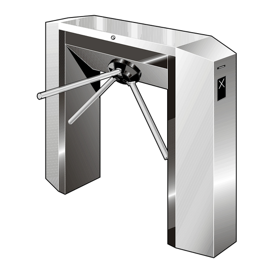
TR491 dropping-arm tripod turnstile
INSTALLATION MANUAL
Automatic Systems s.a.
Head office & factory:
Avenue Mercator 5, 1300 Wavre, Belgium
Tel.: 32-10-23.02.11 Fax: 32-10-23.02.02
Automatic Systems reserves the right to change the characteristics of its products without notice.
Automatic Systems TR491-TR6-GB-a YD-JMW
MQ-1302
20/01/00
Installation TR491
2-1106GB
Rev.: C
Advertisement
Table of Contents

Related Manuals for Automatic Systems TR491


Summary of Contents for Automatic Systems TR491
- Page 1 Automatic Systems s.a. Head office & factory: Avenue Mercator 5, 1300 Wavre, Belgium Tel.: 32-10-23.02.11 Fax: 32-10-23.02.02 Automatic Systems reserves the right to change the characteristics of its products without notice. Automatic Systems TR491-TR6-GB-a YD-JMW MQ-1302 20/01/00 Installation TR491 2-1106GB Rev.: C...
-
Page 2: Table Of Contents
Removing the unit ................... p. 12 3.7. Scrapping the equipment....................p. 12 ANNEX: ELECTRICAL DIAGRAMS (standard version: diagrams Automatic Systems STD 1TR6 04.001 and BT 1TR6 04.002) p. 2/12 Automatic Systems TR491-TR6-GB-a YD-JMW 20/01/00 Installation TR491 2-1106GB Rev.: C... -
Page 3: Introduction
INTRODUCTION We thank you for having chosen the TR491 dropping-arm tripod turnstile designed and manufactured by Automatic Systems. We are confident that your purchase will fully meet your requirements. However, in order to obtain maximum satisfaction from this equipment for a maximum period of time, we strongly advise you to read this manual carefully before installing the equipment. -
Page 4: General
Conventionally and as a general rule, the user will be considered in direction "A" when the turnstile is at his right-hand side, in direction "B" when the turnstile is at his left-hand side. p. 4/12 Automatic Systems TR491-TR6-GB-a YD-JMW 20/01/00 Installation TR491 2-1106GB Rev.: C... -
Page 5: Switching Off The Equipment
(2:2), located under the hood. 2.3. General conditions of use • Your TR491 dropping-arm tripod turnstile has been designed to operate in any climatic environments of -20°C to +60°C, with up to 90% of relative humidity. 2.4. In case of power failure •... -
Page 6: Overall Dimensions And Installation Plan
Cabling to be prepared: Power supply: 230V single-phase + earth (3G x 2.5) Control wiring according to specifications ° 15 EXPANSION BOLT B15/30 -/3413/000 (recommended model) min. 100 Fig. 3 p. 6/12 Automatic Systems TR491-TR6-GB-a YD-JMW 20/01/00 Installation TR491 2-1106GB Rev.: C... -
Page 7: Installation
Check the state of the material. Though it has been carefully packed, damage may have occurred during transport. Any transportation damage should be repaired, or components replaced. p. 7/12 Automatic Systems TR491-TR6-GB-a YD-JMW 20/01/00 Installation TR491 2-1106GB Rev.: C... -
Page 8: Preliminary Work On Site
When the turnstiles are fitted in banks (rows), of more than 1 unit, attention should be given to the linear, vertical and horizontal alignment. Packing shims can be used. p. 8/12 Automatic Systems TR491-TR6-GB-a YD-JMW 20/01/00 Installation TR491 2-1106GB Rev.: C... -
Page 9: Electrical Connections And Initial Power-Up
(2:1) to the ON position. Note: When the turnstile is connected to an IT power system, a 2A two pole circuit breaker must protect the 230V power supply. p. 9/12 Automatic Systems TR491-TR6-GB-a YD-JMW 20/01/00 Installation TR491 2-1106GB Rev.: C... - Page 10 9. "AS-LINK" connector for programming console 19. 230V power supply filter AS1026 board 6. I2C expansion connector 20. Dropping arm test button 21. Dropping arm connector Fig. 5 p. 10/12 Automatic Systems TR491-TR6-GB-a YD-JMW 20/01/00 Installation TR491 2-1106GB Rev.: C...
-
Page 11: Check-List
The dropping-arm tripod turnstile is now operational. Although all adjustments have been carried out in our factory, a final adjustment may be required, following transportation and installation of the equipment. In this case, refer to the Field manual. p. 11/12 Automatic Systems TR491-TR6-GB-a YD-JMW 20/01/00 Installation TR491 2-1106GB Rev.: C... -
Page 12: Temporary Dismantling
(metals, electrical components, plastics, etc.) are handled, recycled, or disposed of in the appropriate method, to comply with regulations and codes of practice in the country where the unit is to be scrapped. p. 12/12 Automatic Systems TR491-TR6-GB-a YD-JMW 20/01/00 Installation TR491 2-1106GB Rev.: C...
Need help?
Do you have a question about the TR491 and is the answer not in the manual?
Questions and answers