
Related Manuals for Automatic Systems SMARTLANE SL 90X


Summary of Contents for Automatic Systems SMARTLANE SL 90X
- Page 1 SMARTLANE Technical Manual NAM-SL 90X-91X-TM-02-EN-E SECURITY ENTRANCE LANES SL 90X – SL 91X SITE PREPARATION INSTALLATION USER MAINTENANCE TECHNICAL MANUAL www.automatic-systems.com...
-
Page 2: Document Revisions
• Sect 17: Wiring diagram updated 2016-06-02 • Sect 17: Wiring diagram updated 2018-09-27 • Updated template p. 2/37 With a constant view to adopting the latest technological developments, Automatic Systems reserves the right to amend the above information at any time www.automatic-systems.com... -
Page 3: Table Of Contents
18. INSTRUCTIONS: FIRST START-UP ..........................34 19. TROUBLESHOOTING..............................35 19.1. Installation troubleshooting ..................................35 19.2. Start-up troubleshooting ..................................35 p. 3/37 With a constant view to adopting the latest technological developments, Automatic Systems reserves the right to amend the above information at any time www.automatic-systems.com... -
Page 4: Safety Warnings
• Keep the circuit breaker turned off for any work that does not require the motor or the programmable logic controller to be turned on. p. 4/37 With a constant view to adopting the latest technological developments, Automatic Systems reserves the right to amend the above information at any time www.automatic-systems.com... - Page 5 SmartLane Security Entrance Lane is factory configured in “minimal risk” mode for its users.) p. 5/37 With a constant view to adopting the latest technological developments, Automatic Systems reserves the right to amend the above information at any time www.automatic-systems.com...
-
Page 6: About The Manuals
6/37 With a constant view to adopting the latest technological developments, Automatic Systems reserves the right to amend the above information at any time www.automatic-systems.com... -
Page 7: Product At A Glance
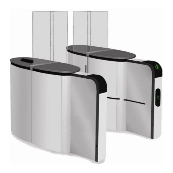
Fixed Glass obstacle Orientation pictogram Unit Extension Inner detection photocells Passageway Figure 1 Lane p. 7/37 With a constant view to adopting the latest technological developments, Automatic Systems reserves the right to amend the above information at any time www.automatic-systems.com... -
Page 8: Definitions
Composed of the housing, detection photocells and motor glass Unit obstacles and (optional) extensions. p. 8/37 With a constant view to adopting the latest technological developments, Automatic Systems reserves the right to amend the above information at any time www.automatic-systems.com... -
Page 9: Types Of Units
This means that the body of an SL 91X will be wider as well to accommodate the wider glass obstacle. p. 9/37 With a constant view to adopting the latest technological developments, Automatic Systems reserves the right to amend the above information at any time www.automatic-systems.com... -
Page 10: Configurations
Slave Unit: Unit located on the user’s left side when the user is moving in direction A. p. 10/37 With a constant view to adopting the latest technological developments, Automatic Systems reserves the right to amend the above information at any time www.automatic-systems.com... -
Page 11: Multiple Lane Configuration Of The Sl 90X Or Sl 91X Lane
It cannot be used as a transition between an array composed of an SL 90X unit and an SL 91X unit. p. 11/37 With a constant view to adopting the latest technological developments, Automatic Systems reserves the right to amend the above information at any time www.automatic-systems.com... -
Page 12: Hybrid Intermediate Unit
• For a right hybrid intermediate unit, the SL 90X glass obstacle (narrower) will be on the right. p. 12/37 With a constant view to adopting the latest technological developments, Automatic Systems reserves the right to amend the above information at any time www.automatic-systems.com... -
Page 13: Components
7. Function pictogram without optional extension – card reader system location 8. Orientation pictogram without optional extension p. 13/37 With a constant view to adopting the latest technological developments, Automatic Systems reserves the right to amend the above information at any time www.automatic-systems.com... -
Page 14: Internal Components
3. Locking mechanism (one per moving glass obstacle 4. Inductive position sensor (one per moving glass obstacle) 5. Electrical panel p. 14/37 With a constant view to adopting the latest technological developments, Automatic Systems reserves the right to amend the above information at any time www.automatic-systems.com... -
Page 15: Mechanical Assembly
6. Crankshaft 7. Release spring 8. Lower rod 9. Lower shaft 10. Higher rod p. 15/37 With a constant view to adopting the latest technological developments, Automatic Systems reserves the right to amend the above information at any time www.automatic-systems.com... -
Page 16: Logic Panels
5. TB3: Terminal block of the PLC 6. AS1162 CAN interface 7. Fuse 8. Programmable logic controller (PLC): Modicon M340 p. 16/37 With a constant view to adopting the latest technological developments, Automatic Systems reserves the right to amend the above information at any time www.automatic-systems.com... -
Page 17: Power Supply Panel
20. CB4: Master motor breaker 21. AS1145 analog signal to CAN interface (also used for the speed controller) p. 17/37 With a constant view to adopting the latest technological developments, Automatic Systems reserves the right to amend the above information at any time www.automatic-systems.com... -
Page 18: Checklist: Required Tools
Tape measure Terminal block screwdriver Vernier caliper Wire stripper Wrench set p. 18/37 With a constant view to adopting the latest technological developments, Automatic Systems reserves the right to amend the above information at any time www.automatic-systems.com... -
Page 19: Checklist: Site Preparation Work
Master/Slave: Low voltage interconnection cable Internal CAN Network cable Network cable for remote control lane (optional) p. 19/37 With a constant view to adopting the latest technological developments, Automatic Systems reserves the right to amend the above information at any time www.automatic-systems.com... -
Page 20: Instructions: Receiving The Unit
Immediately notify your insurance company or your distributor if any damage occurs during transport. p. 20/37 With a constant view to adopting the latest technological developments, Automatic Systems reserves the right to amend the above information at any time www.automatic-systems.com... - Page 21 Disconnect the ground wire and ground protection cable to remove the unit side panel. Figure 10 Removing the side panel p. 21/37 With a constant view to adopting the latest technological developments, Automatic Systems reserves the right to amend the above information at any time www.automatic-systems.com...
- Page 22 Do not twist the housing. The unit may require extensive realignment if the frame or housing is subject to excessive torsion. p. 22/37 With a constant view to adopting the latest technological developments, Automatic Systems reserves the right to amend the above information at any time www.automatic-systems.com...
-
Page 23: Instructions: Installing The Equipment
The base plates must lay flat on leveled ground. Figure 13 Base plates p. 23/37 With a constant view to adopting the latest technological developments, Automatic Systems reserves the right to amend the above information at any time www.automatic-systems.com... - Page 24 • The open face of the bracket should be facing downDrill the holes in the floor for the supplied anchors p. 24/37 With a constant view to adopting the latest technological developments, Automatic Systems reserves the right to amend the above information at any time www.automatic-systems.com...
- Page 25 Shims that are not properly positioned could cause the housing to twist, which could affect the required clearance space. p. 25/37 With a constant view to adopting the latest technological developments, Automatic Systems reserves the right to amend the above information at any time www.automatic-systems.com...
- Page 26 • This clearance space, as well as overall leveling, is critical to proper operation Figure 16 Adjusting the clearance space p. 26/37 With a constant view to adopting the latest technological developments, Automatic Systems reserves the right to amend the above information at any time www.automatic-systems.com...
-
Page 27: Electrical Connections
• To avoid interference, Automatic Systems recommends that the high voltage and low voltage cables be kept at least 4" apart. p. 27/37 With a constant view to adopting the latest technological developments, Automatic Systems reserves the right to amend the above information at any time www.automatic-systems.com... -
Page 28: Preliminary Connections
Note 1: If the installation requires longer cables, the customer will have to supply them. All indicated cable specifications must be met. p. 28/37 With a constant view to adopting the latest technological developments, Automatic Systems reserves the right to amend the above information at any time www.automatic-systems.com... -
Page 29: Fire Or Emergency Exit
SmartLane Security Entrance Lane is prohibited. Use only mechanical relays with quick transfer contacts. Refer to the interconnection wiring diagram for more details. p. 29/37 With a constant view to adopting the latest technological developments, Automatic Systems reserves the right to amend the above information at any time www.automatic-systems.com... -
Page 30: Ground Cable Connections
When mounting the removable panel back onto the frame, make sure the panel is firmly attached to its ground cable and metal wire. p. 30/37 With a constant view to adopting the latest technological developments, Automatic Systems reserves the right to amend the above information at any time www.automatic-systems.com... -
Page 31: Ground Cable Connection Diagram
Technical Manual NAM-SL 90X-91X-TM-02-EN-E 15.1. GROUND CABLE CONNECTION DIAGRAM Figure 18 Ground cable connection p. 31/37 With a constant view to adopting the latest technological developments, Automatic Systems reserves the right to amend the above information at any time www.automatic-systems.com... -
Page 32: Wiring Diagram
SL 90X-91X Technical Manual NAM-SL 90X-91X-TM-02-EN-E 16. Wiring Diagram p. 32/37 With a constant view to adopting the latest technological developments, Automatic Systems reserves the right to amend the above information at any time www.automatic-systems.com... -
Page 33: Checklist: Electrical Connections
Double check that all electrical connections are in accordance with the wiring diagram. p. 33/37 With a constant view to adopting the latest technological developments, Automatic Systems reserves the right to amend the above information at any time www.automatic-systems.com... -
Page 34: Instructions: First Start-Up
• Check that the moving glass obstacle opens completely in the event of a power cut (proper operation of the “anti-panic” system) 12. Switch the main circuit breaker back on p. 34/37 With a constant view to adopting the latest technological developments, Automatic Systems reserves the right to amend the above information at any time www.automatic-systems.com... -
Page 35: Troubleshooting
• Check if anything is obstructing the infrared beam of the detection photocells p. 35/37 With a constant view to adopting the latest technological developments, Automatic Systems reserves the right to amend the above information at any time www.automatic-systems.com... - Page 36 • Reverse 2 phases of the motor (by inverting the U and V cables near the connector) For further troubleshooting, please refer to the Maintenance Manual p. 36/37 With a constant view to adopting the latest technological developments, Automatic Systems reserves the right to amend the above information at any time www.automatic-systems.com...
- Page 37 Fax: +1 450 659 0966 Fax: +1 450 659 0966 Email: helpdesk.nam@automatic-systems.com Email: helpdesk.nam@automatic-systems.com p. 37/37 With a constant view to adopting the latest technological developments, Automatic Systems reserves the right to amend the above information at any time www.automatic-systems.com...
Need help?
Do you have a question about the SMARTLANE SL 90X and is the answer not in the manual?
Questions and answers