
Related Manuals for Automatic Systems SMARTLANE SL 90 Series


Summary of Contents for Automatic Systems SMARTLANE SL 90 Series
- Page 1 SMARTLANE Technical Manual NAM-SL 90X-91X-TM-04-EN-E SECURITY ENTRANCE LANE SL 90X – SL 91X SITE PREPARATION INSTALLATION USER MAINTENANCE TECHNICAL MANUAL www.automatic-systems.com...
-
Page 2: Document Revisions
• -Sect. 10.12: Information on BGF added 2016-02-16 • Sect. 9.3: Maintenance Schedule 2018-09-28 • Updated template p. 2/66 With a constant view to adopting the latest technological developments, Automatic Systems reserves the right to amend the above information at any time www.automatic-systems.com... -
Page 3: Table Of Contents
10.5. Instructions: Adjusting the balancing spring ............................45 10.6. Instructions: Replacing a moving glass obstacle ............................. 46 p. 3/66 With a constant view to adopting the latest technological developments, Automatic Systems reserves the right to amend the above information at any time www.automatic-systems.com... - Page 4 12.3. Gear motor ........................................ 63 12.4. Inductive position sensor ..................................64 12.5. 24-VDC circuit ......................................65 p. 4/66 With a constant view to adopting the latest technological developments, Automatic Systems reserves the right to amend the above information at any time www.automatic-systems.com...
-
Page 5: Safety Warnings
• KEEP YOUR SMARTLANE SECURITY ENTRANCE LANE PROPERLY MAINTAINED as per manufacturer recommendations. p. 5/66 With a constant view to adopting the latest technological developments, Automatic Systems reserves the right to amend the above information at any time www.automatic-systems.com... - Page 6 SmartLane Security Entrance Lane is factory configured in “minimal risk” mode for its users.) p. 6/66 With a constant view to adopting the latest technological developments, Automatic Systems reserves the right to amend the above information at any time www.automatic-systems.com...
-
Page 7: About The Manuals
SmartLane Security Entrance Lane. In it you will find step-by-step instructions on how to proceed along with troubleshooting charts. Save this manual for future reference. p. 7/66 With a constant view to adopting the latest technological developments, Automatic Systems reserves the right to amend the above information at any time www.automatic-systems.com... -
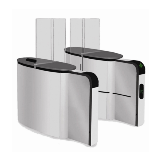
Page 8: Product At A Glance
Fixed Glass Obstacle Orientation pictogram Unit Extension Inner detection photocells Passageway Figure 1 Lane p. 8/66 With a constant view to adopting the latest technological developments, Automatic Systems reserves the right to amend the above information at any time www.automatic-systems.com... -
Page 9: Definitions
Indicates to the user whether the lane is free and the direction to Orientation pictogram follow. Passageway Corridor between 2 units. Programmable logic controller p. 9/66 With a constant view to adopting the latest technological developments, Automatic Systems reserves the right to amend the above information at any time www.automatic-systems.com... - Page 10 Composed of the housing, detection photocells and motors, glass Unit obstacles and (optional) extensions. p. 10/66 With a constant view to adopting the latest technological developments, Automatic Systems reserves the right to amend the above information at any time www.automatic-systems.com...
-
Page 11: Types Of Units
This means that the body of an SL 91X will be wider as well to accommodate the wider glass obstacle. p. 11/66 With a constant view to adopting the latest technological developments, Automatic Systems reserves the right to amend the above information at any time www.automatic-systems.com... -
Page 12: Configurations
Slave Unit: Unit located on the user’s left side when the user is moving in direction A. p. 12/66 With a constant view to adopting the latest technological developments, Automatic Systems reserves the right to amend the above information at any time www.automatic-systems.com... -
Page 13: Multiple Lane Configuration Of The Sl 90X Or Sl 91X Lane
It cannot be used as a transition between an array composed of an SL 90X unit and an SL 91X unit. p. 13/66 With a constant view to adopting the latest technological developments, Automatic Systems reserves the right to amend the above information at any time www.automatic-systems.com... -
Page 14: Hybrid Intermediate Unit
• For a right hybrid intermediate unit, the SL 90X glass obstacle (narrower) will be on the right. p. 14/66 With a constant view to adopting the latest technological developments, Automatic Systems reserves the right to amend the above information at any time www.automatic-systems.com... -
Page 15: Components
7. Function pictogram without optional extension – card reader system location 8. Orientation pictogram without optional extension p. 15/66 With a constant view to adopting the latest technological developments, Automatic Systems reserves the right to amend the above information at any time www.automatic-systems.com... -
Page 16: Internal Components
4. Inductive position sensor (one per moving glass obstacle) 5. Logic assembly 6. Power supply assembly p. 16/66 With a constant view to adopting the latest technological developments, Automatic Systems reserves the right to amend the above information at any time www.automatic-systems.com... -
Page 17: Mechanical Assembly
6. Crankshaft 7. Release spring 8. Lower rod 9. Lower shaft 10. Higher rod p. 17/66 With a constant view to adopting the latest technological developments, Automatic Systems reserves the right to amend the above information at any time www.automatic-systems.com... -
Page 18: Logic Panels
5. TB3: Terminal block of the PLC 6. AS1162 CAN interface 7. Fuse 8. Programmable logic controller (PLC): Modicon M340 p. 18/66 With a constant view to adopting the latest technological developments, Automatic Systems reserves the right to amend the above information at any time www.automatic-systems.com... -
Page 19: Power Supply Panel
20. CB4: Master motor breaker 21. AS1145 analog signal to CAN interface (also used for the speed controller) p. 19/66 With a constant view to adopting the latest technological developments, Automatic Systems reserves the right to amend the above information at any time www.automatic-systems.com... -
Page 20: Diras Assemblies
Detection zone B Receiver (slave) side Figure 10 Type of DIRAS board according to lane configuration p. 20/66 With a constant view to adopting the latest technological developments, Automatic Systems reserves the right to amend the above information at any time www.automatic-systems.com... -
Page 21: Maintenance Guidelines
(e.g., at the entrance of a swimming pool, near the sea or in an industrial environment). p. 21/66 With a constant view to adopting the latest technological developments, Automatic Systems reserves the right to amend the above information at any time www.automatic-systems.com... -
Page 22: Ordering Parts
*LOCATING THE INFORMATION OF YOUR SL ON THE IDENTIFICATION PLATE Model number Serial Number Figure 11 Identification plate p. 22/66 With a constant view to adopting the latest technological developments, Automatic Systems reserves the right to amend the above information at any time www.automatic-systems.com... -
Page 23: Required Tools
• Ratchet extension • 10 mm socket • 13 mm socket • 19mm socket p. 23/66 With a constant view to adopting the latest technological developments, Automatic Systems reserves the right to amend the above information at any time www.automatic-systems.com... -
Page 24: Maintenance Schedule
Stainless steel housing Stainless cleaner Sprayon #50050 • Test SL in entrance and exit p. 24/66 With a constant view to adopting the latest technological developments, Automatic Systems reserves the right to amend the above information at any time www.automatic-systems.com... - Page 25 Stainless steel housing Stainless cleaner Sprayon #50050 • Test SL in entrance and exit p. 25/66 With a constant view to adopting the latest technological developments, Automatic Systems reserves the right to amend the above information at any time www.automatic-systems.com...
- Page 26 Stainless steel housing Stainless cleaner Sprayon #50050 Test SL in entrance and exit p. 26/66 With a constant view to adopting the latest technological developments, Automatic Systems reserves the right to amend the above information at any time www.automatic-systems.com...
- Page 27 Inspect and clean all Plexiglas Test SL in entrance and exit High glass only Requires parts p. 27/66 With a constant view to adopting the latest technological developments, Automatic Systems reserves the right to amend the above information at any time www.automatic-systems.com...
-
Page 28: Recommended Spare Parts List (Recommended Quantities For Every Set Of 6 Sl Units)
ORIENTATION PICTO BOARD SL9X1 SL9X1 & 0/7140/294 ORIENTATION PICTO BOARD EXTENSION SL9X2 0/7140/295 FUNCTION PICTO BOARD p. 28/66 With a constant view to adopting the latest technological developments, Automatic Systems reserves the right to amend the above information at any time www.automatic-systems.com... - Page 29 RECOMMENDED LUBRICATION AND CLEANING SUPPLIES 0/6950/371 DOW CORNING LUBRICANT PASTE #111 0/7532/025 VAL-PLEX LITHIUM GREASE p. 29/66 With a constant view to adopting the latest technological developments, Automatic Systems reserves the right to amend the above information at any time www.automatic-systems.com...
-
Page 30: Inspection Guidelines
10.2 1.15 23.5 2.65 1053 47.8 1600 78.8 2200 128.3 14.5 3150 194.7 4250 p. 30/66 With a constant view to adopting the latest technological developments, Automatic Systems reserves the right to amend the above information at any time www.automatic-systems.com... -
Page 31: Motors
• TB9-4: 1 A, fast-acting • FU1: 3 A, fast-acting Figure 12 Fuses locations p. 31/66 With a constant view to adopting the latest technological developments, Automatic Systems reserves the right to amend the above information at any time www.automatic-systems.com... -
Page 32: Crankshaft Assembly
Grease bushing [1] on both sides (see Figure 13). Inspect rubber bumpers [2]. p. 32/66 With a constant view to adopting the latest technological developments, Automatic Systems reserves the right to amend the above information at any time www.automatic-systems.com... -
Page 33: Mechanical Release System: Lever And Spring
Verify the integrity of the power cables of the solenoid [2]. Make sure nuts are properly tightened. p. 33/66 With a constant view to adopting the latest technological developments, Automatic Systems reserves the right to amend the above information at any time www.automatic-systems.com... -
Page 34: Inductive Position Sensor
Look for premature damage, and plastic and metal grindings. Grease moving parts, bushings and bearings. p. 34/66 With a constant view to adopting the latest technological developments, Automatic Systems reserves the right to amend the above information at any time www.automatic-systems.com... -
Page 35: Plinth
17). Refer to Section 10.6. for more details on adjustment. Grease moving parts and bushings. p. 35/66 With a constant view to adopting the latest technological developments, Automatic Systems reserves the right to amend the above information at any time www.automatic-systems.com... -
Page 36: Balancing Springs And Adjustment
[11] and Figure 17 item [3]). The shutter guides are the gray channels p. 36/66 With a constant view to adopting the latest technological developments, Automatic Systems reserves the right to amend the above information at any time www.automatic-systems.com... -
Page 37: Diras
DIRAS. Verify connections. p. 37/66 With a constant view to adopting the latest technological developments, Automatic Systems reserves the right to amend the above information at any time www.automatic-systems.com... -
Page 38: Plexiglas Surfaces
Make sure all wires and cables are firmly connected. 9.17. NUTS AND BOLTS Verify and tighten all nuts and bolts. p. 38/66 With a constant view to adopting the latest technological developments, Automatic Systems reserves the right to amend the above information at any time www.automatic-systems.com... -
Page 39: Panel Locks
Inspect the housing for abnormal scratches, damages, or misalignment of housing components. Clean the housing with stainless steel cleaner Sprayon (No. 50050), or equivalent. p. 39/66 With a constant view to adopting the latest technological developments, Automatic Systems reserves the right to amend the above information at any time www.automatic-systems.com... -
Page 40: Instructions: Mechanical Adjustements And Operations
To avoid modifying the alignment of the DIRAS, do not tighten the thumbscrews too much when putting the cover plate back on. p. 40/66 With a constant view to adopting the latest technological developments, Automatic Systems reserves the right to amend the above information at any time www.automatic-systems.com... -
Page 41: Instructions: Removing The Cover Plate
2. Remove the 3 thumbscrews fastening the cover plate to the frame. Figure 25 Cover plate thumbscrews p. 41/66 With a constant view to adopting the latest technological developments, Automatic Systems reserves the right to amend the above information at any time www.automatic-systems.com... -
Page 42: Instructions: Adjusting The Obstacle Clearance Space
25 mm ± 0.5 mm = 0.98 in ± 0.02 in B = Shims (3/8" max) Figure 26 Adjusting the gap p. 42/66 With a constant view to adopting the latest technological developments, Automatic Systems reserves the right to amend the above information at any time www.automatic-systems.com... -
Page 43: Instructions: Replacing The Balancing Spring
9. To reinstall the balancing spring assembly, proceed in the reverse order. 10. To adjust the balancing spring assembly, see Section 10.5. p. 43/66 With a constant view to adopting the latest technological developments, Automatic Systems reserves the right to amend the above information at any time www.automatic-systems.com... - Page 44 5, 6 or 7 to compress the springs more or less. Figure 27 Balancing spring assembly p. 44/66 With a constant view to adopting the latest technological developments, Automatic Systems reserves the right to amend the above information at any time www.automatic-systems.com...
-
Page 45: Instructions: Adjusting The Balancing Spring
Double spring adjustment Table 2 Adjusting the balancing spring of model SL 91x p. 45/66 With a constant view to adopting the latest technological developments, Automatic Systems reserves the right to amend the above information at any time www.automatic-systems.com... -
Page 46: Instructions: Replacing A Moving Glass Obstacle
10. Verify that the obstacle is leveled and then tighten all bolts ([4] and [5]). 11. To prevent the moving obstacle from striking the shutter during normal operation: p. 46/66 With a constant view to adopting the latest technological developments, Automatic Systems reserves the right to amend the above information at any time www.automatic-systems.com... - Page 47 29) to obtain the proper clearance. 12. Remove the shim. Figure 29 Plinth assembly Figure 28 Shim location p. 47/66 With a constant view to adopting the latest technological developments, Automatic Systems reserves the right to amend the above information at any time www.automatic-systems.com...
-
Page 48: Instructions: Replacing A Fixed Glass Obstacle
7. Fit the new fixed glass obstacle in its bracket and tighten the mounting bolts [6]. Figure 30 Fixed obstacle mounting bolts p. 48/66 With a constant view to adopting the latest technological developments, Automatic Systems reserves the right to amend the above information at any time www.automatic-systems.com... -
Page 49: Instructions: Replacing The Shutter, Shutter Guides, Shutter Protectors And Sliding Bands
8. To separate the shutter [11] from the shutter rod [12], remove the screw [10]. 9. To replace the shutter [11]: • Clean the shutter guide grooves. p. 49/66 With a constant view to adopting the latest technological developments, Automatic Systems reserves the right to amend the above information at any time www.automatic-systems.com... - Page 50 • Remove the 2 M4x16mm bolts, nylon spacers and M4 washers located near the ground cable [8] (see Figure Figure 32 Figure 33). Figure 31 Shutter assembly p. 50/66 With a constant view to adopting the latest technological developments, Automatic Systems reserves the right to amend the above information at any time www.automatic-systems.com...
- Page 51 Figure 32 Shutter protector bolt assembly for both types of (intermediate unit model shown) SmartLane units p. 51/66 With a constant view to adopting the latest technological developments, Automatic Systems reserves the right to amend the above information at any time www.automatic-systems.com...
-
Page 52: Instructions: Replacing The Release Spring
3. Replace the release spring located between positions [15] and [16] (see Figure 34). Solenoid Figure 34 Release spring p. 52/66 With a constant view to adopting the latest technological developments, Automatic Systems reserves the right to amend the above information at any time www.automatic-systems.com... -
Page 53: Instructions: Replacing The Inductive Position Sensor
6. Initialize the inductive position sensor using the Maintenance panel (refer to Sensor initialization in Maintenance mode in the Maintenance Panel Manual). Solenoid Figure 35 Inductive position sensor p. 53/66 With a constant view to adopting the latest technological developments, Automatic Systems reserves the right to amend the above information at any time www.automatic-systems.com... -
Page 54: Instructions: Replacing The Locking Mechanism
4. To replace the conical spring [2] only, complete steps 1 and 2 and simply pull out the solenoid shaft to access the conical spring. Replace it. Figure 36 Locking mechanism p. 54/66 With a constant view to adopting the latest technological developments, Automatic Systems reserves the right to amend the above information at any time www.automatic-systems.com... -
Page 55: Instructions: Removing The Gear Motor
4. Remove the motor (a pry bar may be inserted into the upper part of the mounting plate [B] to act as a lever arm). Figure 37 Gear motor p. 55/66 With a constant view to adopting the latest technological developments, Automatic Systems reserves the right to amend the above information at any time www.automatic-systems.com... -
Page 56: Instructions: Removing The Mechanical Assembly
7. Take the mechanical assembly (see Figure 7) out of the housing. Figure 38 Mechanical assembly mounting bolts p. 56/66 With a constant view to adopting the latest technological developments, Automatic Systems reserves the right to amend the above information at any time www.automatic-systems.com... -
Page 57: Instructions: Removing The Orientation Pictogram Board From The Housing
Figure 39 Orientation pictogram board in units Left: Without extension Right: With extension p. 57/66 With a constant view to adopting the latest technological developments, Automatic Systems reserves the right to amend the above information at any time www.automatic-systems.com... -
Page 58: Instructions: Removing The Function Pictogram Board From The Housing
Figure 40 Function pictogram assembly in unit Left: Without extension Right: With extension p. 58/66 With a constant view to adopting the latest technological developments, Automatic Systems reserves the right to amend the above information at any time www.automatic-systems.com... -
Page 59: Wiring Diagram
SL 90X-91X Technical Manual NAM-SL 90X-91X-TM-04-EN-E 11. Wiring diagram p. 59/66 With a constant view to adopting the latest technological developments, Automatic Systems reserves the right to amend the above information at any time www.automatic-systems.com... -
Page 60: Troubleshooting
SL 90X-91X Technical Manual NAM-SL 90X-91X-TM-04-EN-E 12. Troubleshooting p. 60/66 With a constant view to adopting the latest technological developments, Automatic Systems reserves the right to amend the above information at any time www.automatic-systems.com... -
Page 61: Release Mechanism - Power Outage Situation
Replace motor Does Motor crank Release spring mechanism turns with rod damaged? unlock? disconected? p. 61/66 With a constant view to adopting the latest technological developments, Automatic Systems reserves the right to amend the above information at any time www.automatic-systems.com... -
Page 62: Safety Shutter
Shim gate to have an obstacle clearance space of 25mm wide p. 62/66 With a constant view to adopting the latest technological developments, Automatic Systems reserves the right to amend the above information at any time www.automatic-systems.com... -
Page 63: Gear Motor
Cable between electrical box Connect cable and VSC connected?? Replace Refer to VFD gearmotor troubleshooting p. 63/66 With a constant view to adopting the latest technological developments, Automatic Systems reserves the right to amend the above information at any time www.automatic-systems.com... -
Page 64: Inductive Position Sensor
PS1 output = open/close 24VDC? correctly? Done Replace Inductive position sensor Call Automatic Systems p. 64/66 With a constant view to adopting the latest technological developments, Automatic Systems reserves the right to amend the above information at any time www.automatic-systems.com... -
Page 65: 24-Vdc Circuit
PLC from TB2. 24VDC? OUTPUT Fixed? from TB2. Fixed? Fixed? Power at TB6 = Done 24VDC? p. 65/66 With a constant view to adopting the latest technological developments, Automatic Systems reserves the right to amend the above information at any time www.automatic-systems.com... - Page 66 Fax: +1 450 659 0966 Fax: +1 450 659 0966 Email: helpdesk.nam@automatic-systems.com Email: helpdesk.nam@automatic-systems.com p. 66/66 With a constant view to adopting the latest technological developments, Automatic Systems reserves the right to amend the above information at any time www.automatic-systems.com...
Need help?
Do you have a question about the SMARTLANE SL 90 Series and is the answer not in the manual?
Questions and answers