Table of Contents
Advertisement
Quick Links
QuickStart Instructions
KEIL-Kit
nanoMODUL-STM32F103
Using Keil's ULINK and the Keil Microcontroller
Development Tool Chain
Note: The PHYTEC Kit CD includes the electronic version of
the English nanoMODUL-STM32F103 Hardware Manual
Edition: August 2009
A product of a PHYTEC Technology Holding company
Advertisement
Table of Contents

Related Manuals for Phytec KEIL nanoMODUL-STM32F103


Summary of Contents for Phytec KEIL nanoMODUL-STM32F103
- Page 1 QuickStart Instructions KEIL-Kit nanoMODUL-STM32F103 Using Keil's ULINK and the Keil Microcontroller Development Tool Chain Note: The PHYTEC Kit CD includes the electronic version of the English nanoMODUL-STM32F103 Hardware Manual Edition: August 2009 A product of a PHYTEC Technology Holding company...
- Page 2 Additionally, PHYTEC Messtechnik GmbH offers no guarantee nor accepts any liability for damages arising from the improper usage or improper installation of the hardware or software. PHYTEC Messtechnik GmbH further reserves the right to alter the layout and/or design of the hardware without prior notification and accepts no liability for doing so.
-
Page 3: Table Of Contents
2.4 Keil RealView Microcontroller Development Kit ....... 3 Getting Started ..................4 3.1 Installing Rapid Development Kit Software ........4 3.1.1 Installing Documentation from PHYTEC Kit CD ....4 3.1.2 Installing Keil Microcontroller Development Tools....5 3.2 Interfacing the nanoMODUL-STM32F103 to a Host-PC....6 3.3 Downloading Blinky Example Code with μVision3 ...... -
Page 5: Introduction To The Rapid Development Kit
The nanoMODUL-STM32F103 module is designed to be plugged into a PHYTEC Carrier Board. The PHYTEC Carrier Board contains the I/O connectors as well as any other interface circuitry not provided on the nanoMODUL module itself. The nanoMODUL module, combined with the PHYTEC Carrier Board, provides a platform to jump start embedded designs and propel concept to prototype and finished product. -
Page 6: System Description
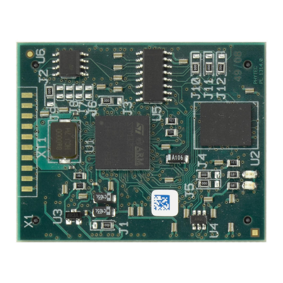
QuickStart Instructions 2 System Description 2.1 Hardware Description The following PHYTEC hardware components are included in the nanoMODUL-STM32F103 Keil Rapid Development Kit (part number KNM-103-KEIL) and are necessary for completing the instructions in this QuickStart instruction: • the PHYTEC nanoMODUL-STM32F103 (NM-103) •... -
Page 7: The Phytec Nanomodul-Stm32F103
µVision3 features. For more information on Keil ARM/µVision3 tools visit their website at: http://www.keil.com/arm/ For more information and example updates, please refer to the following sources: http://www.phytec.com - or - http://www.phytec.de support@phytec.com - or - support@phytec.de http://www.keil.com support@keil.com © PHYTEC Messtechnik GmbH, Germany 2009 L-739e_2... -
Page 8: Getting Started
The PHYTEC Kit CD installs documentation, datasheets, and demo files for the nanoMODUL- STM32F103. When you insert the PHYTEC Kit CD into the CD-ROM drive of your host-PC, the CD should automatically launch a setup program. Otherwise the setup program (setup.exe) can be manually executed from the root of the CD. -
Page 9: Installing Keil Microcontroller Development Tools
Install the Keil ARM Evaluation tools, from the enclosed Keil Microcontroller Development Tools CD, following the steps indicated in the install procedure. • Alternately, the Keil ARM Evaluation tools can be installed from: https://www.keil.com/demo/eval/arm.htm © PHYTEC Messtechnik GmbH, Germany 2009 L-739e_2... -
Page 10: Interfacing The Nanomodul-Stm32F103 To A Host-Pc
The nanoMODUL and Carrier Board should now be properly connected to a host PC via the Keil ULINK. You are now ready to use the Keil Development Tools to establish communication between the host-PC and target hardware. © PHYTEC Messtechnik GmbH, Germany 2009 L-739e_2... -
Page 11: Downloading Blinky Example Code With Μvision3
The Blinky project, when executed, manipulates a user LED on the nanoMODUL. The Blinky example contains one target: − nanoModul-STM32F103: configured for on-chip flash Open Blinky project by selecing Project / Open Project from the μVision3 menu and browse to C:\PHYTEC\nanoMODUL-STM32F103\Keil-Kit\Quickstart\Demos\Blinky © PHYTEC Messtechnik GmbH, Germany 2009 L-739e_2... - Page 12 Select the Blinky.Uv2 projectfile and click Open. If the Blinky.c source file is not already visible in the editor window you can open it by double-clicking on its file name in the project workspace: © PHYTEC Messtechnik GmbH, Germany 2009 L-739e_2...
-
Page 13: Build The Project
If the data transfer was successful, a screen similar to the one shown below will appear. The Project Workspace window changes to the Register page. The debug toolbar is also displayed. In the lower part of the debug screen you will see the Command window. © PHYTEC Messtechnik GmbH, Germany 2009 L-739e_2... - Page 14 Window – Register page showing the start address of the 'main' function. • Click on the Run icon and the program will run. Successful execution of the program will blink LED D1 on the nanoMODUL. © PHYTEC Messtechnik GmbH, Germany 2009 L-739e_2...
-
Page 15: Debugging
Run button is pushed. • The next button on the debugger toolbar is the Stop button. The Stop button interrupts and stops the running program at an undetermined location. © PHYTEC Messtechnik GmbH, Germany 2009 L-739e_2... - Page 16 The last button on the debugger toolbar performs the Run to Cursor line command. The Run to Cursor line command executes the program to the current cursor position within the code window. This allows use of the cursor line as a temporary breakpoint. © PHYTEC Messtechnik GmbH, Germany 2009 L-739e_2...
-
Page 17: Debugging Modes
The Simulator allows PC-based simulation of most features of the STM32F103 microcontroller without actually having target hardware. You can test and debug your embedded application before the hardware is ready. µVision3 simulates a wide variety of peripherals, including external © PHYTEC Messtechnik GmbH, Germany 2009 L-739e_2... - Page 18 Debugging on the target hardware also enables the testing of peripheral components of the application and real-time program execution. The Blinky demo in this section utilizes the ULINK Cortex Debugger environment. • The ULINK Cortex Debugger settings can be viewed by selecting the Settings button: © PHYTEC Messtechnik GmbH, Germany 2009 L-739e_2...
-
Page 19: Starting The Debugger
To start the ARM/µVision3 debug environment, click on the debugger icon toolbar. • Click on the Run icon and the program will run. Successful execution of the program will blink LED D1 on the nanoMODUL. © PHYTEC Messtechnik GmbH, Germany 2009 L-739e_2... -
Page 20: Internal Flash Programming
Wait until the programming is complete. This is indicated by the "Verify OK" message. The download utility will perform a reset and code will execute without further user interaction. Successful execution of the program will blink LED D1 on nanoMODUL. © PHYTEC Messtechnik GmbH, Germany 2009 L-739e_2... -
Page 21: Getting More Involved
Advanced users can modify the target, compiler and linker settings from the Options for Target area by selecting the Options for Target icon on the build toolbar or from the main toolbar menu select Project / Options for the Target 'nanoMODUL-STM32F103'. © PHYTEC Messtechnik GmbH, Germany 2009 L-739e_2... - Page 22 QuickStart Instructions © PHYTEC Messtechnik GmbH, Germany 2009 L-739e_2...
- Page 23 How would you improve this manual? Did you find any mistakes in this manual? page Submitted by: Customer number: Name: Company: Address: Return to: PHYTEC Technologie Holding AG Robert-Koch-Str. 39 55129 Mainz Fax: +49 (6131) 9221-26 support@phytec.de © PHYTEC Messtechnik GmbH, Germany 2009 L-739e_2...
- Page 24 Published by © PHYTEC Messtechnik GmbH, Germany 2009 Document Number: L-739e_2 Printed in Germany...
Need help?
Do you have a question about the KEIL nanoMODUL-STM32F103 and is the answer not in the manual?
Questions and answers