Table of Contents
Advertisement
Quick Links
Advertisement
Table of Contents

Related Manuals for Phytec phyCORE-AM335 Series


Summary of Contents for Phytec phyCORE-AM335 Series
- Page 1 Hardware Manual Document No: L-771e_0 SOM Product No:PCM-051 SOM PCB No:1358.1 Carrier Board Product No:PCM-953 Carrier Board PCB No:1359.1 GPIO Expansion Board Product No: PCM-957 Edition June 2012 A product of a PHYTEC Technology Holding company...
- Page 2 PHYTEC Messtechnik GmbH reserves the right to alter the information contained herein without prior notification and accepts no responsibility for any damages which might result.
-
Page 3: Table Of Contents
1.9.1Universal Asynchronous Receiver/Transmitter Interfaces (UARTs)..30 1.9.2USB-OTG interfaces ..............31 1.9.3Ethernet1 with PHY (U3)............32 1.9.4Ethernet 2 ................33 1.9.5Profibus ................33 1.9.6I²C Interface .................33 1.9.7SPI Interfaces ...............34 1.9.8Controller Area Network (CAN) Interfaces ........35 1.9.9Multichannel Audio Serial Ports (McASP) ........35 © 2012 L-771e_0 PHYTEC Messtechnik GmbH... - Page 4 2.1.2.15JTAG (X21)..............70 2.1.2.16Display / Touch (X4)............ 72 2.1.2.16.1Parallel Display Interface Connector (X4) ....73 2.1.2.16.2PDI Power Connector (X31) ........75 2.1.2.17MMC/SD (X20) ............76 2.1.2.18McASP (X14, X15, X16, X17).......... 77 2.1.2.19WiFi (X27)..............79 © 2012 PHYTEC Messtechnik GmbH L-771e_0...
- Page 5 3.3 GPIO Expansion Board GPIO Signals ..........82 3.4 GPIO Expansion Board GPMC Signals ..........82 3.5 GPIO Expansion Board Power Signals ..........83 3.6 GPIO Expansion Board Serial Interfaces ..........83 3.7 Signals Not Connected to the GPIO Expansion Board ......85 © 2012 L-771e_0 PHYTEC Messtechnik GmbH...
- Page 6 © 2012 PHYTEC Messtechnik GmbH L-771e_0...
- Page 7 USB Connectors for Different Operating Modes ............68 Table 29: Carrier Board JTAG Connector X21..............71 Table 30: Table 31: PDI Connector X4 Signal Description ..............73 Table 32: Auxiliary Interfaces at LVDS Display Connector X4 ..........75 © 2012 L-771e_0 PHYTEC Messtechnik GmbH...
- Page 8 GPIO Expansion Board Power Signal Map ............83 Table 41: GPIO Expansion Board Serial Interfaces Signal Map ..........83 AM335x SOM Signals Not Routed to the GPIO Expansion Connector X5 ..... 85 Table 42: © 2012 PHYTEC Messtechnik GmbH L-771e_0...
- Page 9 Figure 25: USB Connectors and Jumpers................67 Figure 26: X5 GPIO Expansion Board Connectors ..............69 Figure 27: JTAG Connector.....................70 Figure 28: Display Connectors ..................72 Figure 29: MMC/SD Connector ..................76 Figure 30: Audio Connectors ..................77 Figure 31: WiFi Connector....................79 © 2012 L-771e_0 PHYTEC Messtechnik GmbH...
- Page 10 © 2012 PHYTEC Messtechnik GmbH L-771e_0...
-
Page 11: Conventions, Abbreviations And Acronyms
5V_PD LVDS Differential line pairs 100 Ohm LVDS Pegel LVDS Differential 90 Ohm Differential line pairs 90 Ohm DIFF90 Differential 100 Ohm Differential line pairs 100 Ohm DIFF100 Analog Analog input or output Analog L-771e_0 © PHYTEC Messtechnik GmbH 2012... - Page 12 Solder jumper; these types of jumpers require solder equipment to remove and place. Solderless jumper; these types of jumpers can be removed and placed by hand with no special tools. Printed circuit board PHYTEC Display Interface; defined to connect PHYTEC display adapter boards, or custom adapters. PHYTEC Extension Board PMIC...
- Page 13 For this reason, this manual contains no detailed description of the controller's registers, or information relevant for software development. Please refer to the AM335x Technical Reference Manual, if such information is needed to connect customer designed applications. L-771e_0 © PHYTEC Messtechnik GmbH 2012...
-
Page 14: Preface
This phyCORE-AM335x Hardware Manual has three sections. The first section describes the System on Module's design and functions. The second section describes the PHYTEC Carrier Board for the SOM. And the third section describes the GPIO Expansion Board that can connect to the Carrier Board. -
Page 15: Part I: Pcm-051/Phycore-Am335X System On Module
1358.1 PCB revision of the phyCORE-AM335x SOM. 1.1 Introduction The phyCORE-AM335x is one of a series of PHYTEC System on Modules (SOMs) that can be populated with differ- ent controllers and, hence, offers various functions and configurations. PHYTEC supports a variety of 8-/16- and 32-bit controllers in two ways: 1. -
Page 16: 1Block Diagram
Support of standard 20 pin debug interface through JTAG connector • 3x I²C interfaces • 2x SPI interfaces • 3x SD/MMC card interfaces • Real-Time Clock • 2x Multi-channel audio serial interfaces (McASP) 1.1.1 Block Diagram Figure 1: Block Diagram of the phyCORE-AM335x © 2012 PHYTEC Messtechnik GmbH L-771e_0... -
Page 17: 2View Of The Phycore-Am335X
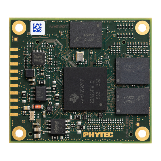
Part I: PCM-051/phyCORE-AM335x System on Module 1.1.2 View of the phyCORE-AM335x Figure 2: Top View of the phyCORE-AM335x (controller side) L-771e_0 © PHYTEC Messtechnik GmbH 2012... -
Page 18: Figure 3: Bottom View Of The Phycore-Am335X (Connector Side)
Part I: PCM-051/phyCORE-AM335x System on Module phyCORE-AM335x Figure 3: Bottom View of the phyCORE-AM335x (connector side) © 2012 PHYTEC Messtechnik GmbH L-771e_0... -
Page 19: 3Minimum Requirements To Operate The Phycore-Am335X
In addition, proper implementation of the phyCORE-AM335x module into a target application also requires connecting all GND pins neighboring signals that are being used in the application circuitry. Please refer to Section 1.4 for more information. L-771e_0 © PHYTEC Messtechnik GmbH 2012... -
Page 20: Phycore Connectors And Pins
Since most of the controller pins are multiplexed with multiple functions, the table relates only to the pin functions as they are used with PHYTEC's carrier board. This means that you can use any of the other pin multi- ©... - Page 21 Please refer to the Texas Instruments AM335x Technical Reference Manual for details on its functions and features. Note SL is short for Signal Level (V) and is the applicable logic level to interface a given pin.Those pins marked as “N/A” have a range of acceptable values. L-771e_0 © PHYTEC Messtechnik GmbH 2012...
-
Page 22: Table 1: Pinout Of The Phycore-Connector X1, Row A
X1.21A - Reserved, no-connect X1.22A GND Ground X1.23A GPMC_AD0 VMMC_3P3V General Purpose Memory Controller interface Address/Data X1.24A GPMC_AD2 VMMC_3P3V General Purpose Memory Controller interface Address/Data Table 1: Pinout of the phyCORE-Connector X1, Row A © 2012 PHYTEC Messtechnik GmbH L-771e_0... - Page 23 7 or PRU Ethernet1 Rx clock X1.45A RGMII2_RD1 / P_MII1_RXDV IO VAUX2_3P3V Ethernet 2 RGMII Rx data 1 or PRU Ethernet1 Rx data valid Table 1: Pinout of the phyCORE-Connector X1, Row A L-771e_0 © PHYTEC Messtechnik GmbH 2012...
-
Page 24: Table 2: Pinout Of The Phycore-Connector X1, Row B
VBAT_4I2C_RTC (3 V) External RTC interrupt (low-true) X1.17B GPMC_WEn VMMC_3P3V General Purpose Memory Controller write enable X1.18B GPIO_3_8 VMMC_3P3V AM335x GPIO_3_8 X1.19B GND Ground X1.20B GPIO_3_7 VMMC_3P3V AM335x GPIO_3_7 Table 2: Pinout of the phyCORE-Connector X1, Row B © 2012 PHYTEC Messtechnik GmbH L-771e_0... - Page 25 X1.42B RGMII2_TCTL / VAUX2_3P3V Ethernet2 Tx control or PRU Ethernet1 P_MII1_MT_CLK Tx clock X1.43B - Reserved, no-connect X1.44B GND Ground X1.45B CLKOUT1 VMMC_3P3V AM335x CLKOUT1, 25 MHz Table 2: Pinout of the phyCORE-Connector X1, Row B L-771e_0 © PHYTEC Messtechnik GmbH 2012...
- Page 26 X1.46B MMC2_CMD / P_MDIO_DATA VAUX2_3P3V MMC/SDIO2 command or PRU MDIO data X1.47B GPIO_1_30 VMMC_3P3V AM335x GPIO_1_30 X1.48B GPIO_1_31 VMMC_3P3V AM335x GPIO_1_31 X1.49B GND Ground X1.50B - Reserved, no-connect Table 2: Pinout of the phyCORE-Connector X1, Row B © 2012 PHYTEC Messtechnik GmbH L-771e_0...
-
Page 27: Table 3: Pinout Of The Phycore-Connector X3, Row A
I²C bus 0 data. X3.A21 Ground X3.A22 MCASP0_AXR0 VMMC_3P3V Multi-channel Audio Serial Port 0 data 0 X3.A23 GPIO_3_17 VMMC_3P3V AM335x GPIO3_17 X3.A24 DCAN0_RX VMMC_3P3V CAN0 Rx data Table 3: Pinout of the phyCORE-Connector X3, Row A L-771e_0 © PHYTEC Messtechnik GmbH 2012... - Page 28 VMMC_3P3V LCD data 8 or PRU Ethernet 0 Rx data 3 X3.A53 LCD_D14 / P_MII0_MR_CLK VMMC_3P3V LCD data 14 or PRU Ethernet 0 Rx clock Table 3: Pinout of the phyCORE-Connector X3, Row A © 2012 PHYTEC Messtechnik GmbH L-771e_0...
- Page 29 LCD data 9 or PRU Ethernet 0 Rx data 2 X3.A59 LCD_D10 / P_MII0_RXD1 VMMC_3P3V LCD data 10 or PRU Ethernet 0 Rx data 1 X3.A60 UART2_RX VAUX2_3P3V UART 2 Rx data to AM335x Table 3: Pinout of the phyCORE-Connector X3, Row A L-771e_0 © PHYTEC Messtechnik GmbH 2012...
-
Page 30: Table 4: Pinout Of The Phycore-Connector X3, Row B
VPLL_1P8V AM335x analog input/output 6 X3.B30 GNDA_ADC Analog ground X3.B31 AIN5 analog VPLL_1P8V AM335x analog input/output 5 X3.B32 AIN4 analog VPLL_1P8V AM335x analog input/output 4 Table 4: Pinout of the phyCORE-Connector X3, Row B © 2012 PHYTEC Messtechnik GmbH L-771e_0... - Page 31 MMC / SDIO 0 data 2 X3.B59 MMC0_D3 VAUX2_3P3V MMC / SDIO 0 data 3 X3.B60 UART2_TX VAUX2_3P3V UART 2 Tx data to Carrier Board Table 4: Pinout of the phyCORE-Connector X3, Row B L-771e_0 © PHYTEC Messtechnik GmbH 2012...
-
Page 32: Jumpers
Please pay special attention to the "TYPE" column to ensure you are using the correct type of jumper (0 Ohms, 10k Ohms, etc…). The jumpers are either 0805 package or 0402 package with a 1/8W or larger power rating. © 2012 PHYTEC Messtechnik GmbH L-771e_0... -
Page 33: Figure 5: Jumper Locations (Top View)
Part I: PCM-051/phyCORE-AM335x System on Module Figure 5: Jumper Locations (Top View) L-771e_0 © PHYTEC Messtechnik GmbH 2012... -
Page 34: Table 5: Som Jumper Settings
Selects the COL/CRS PHY signal for ETH1 0R (0402) Section 1.9.3 Selects the COL/CRS PHY signal for ETH1 in RMII mode Selects the COL/CRS PHY signal for ETH1 in MII mode. Table 5: SOM Jumper Settings © 2012 PHYTEC Messtechnik GmbH L-771e_0... - Page 35 The RTC does not run when the system is off VBACKUP connects to the VBAT_IN_4RTC backup battery supply from the carrier board. The RTC runs when the system is off Table 5: SOM Jumper Settings L-771e_0 © PHYTEC Messtechnik GmbH 2012...
-
Page 36: Power
AM335x RTC when the primary system power is off. Carrier Boards for applications not requiring a backup mode should connect the VBAT pin to the VDD_5V_IN primary system power supply. © 2012 PHYTEC Messtechnik GmbH L-771e_0... -
Page 37: 3Power Management Ic (U4)
It is connected to the AM335x via the I2C0 interface. The I2C0 addresses of the TPS65910A3 PMIC are 0x2D and 0x412 (hexadecimal). Refer to the Texas Instruments TPS65910 datasheet for details about the PMIC's registers and operation. Figure 6: AM335x SOM Power Scheme L-771e_0 © PHYTEC Messtechnik GmbH 2012... -
Page 38: Backup Battery Management
VDD_5V_IN, through a charger integrated in the TPS65910A3. The backup battery charge voltage and enable are controlled through the BBCH_REG register. The contents of this register are maintained during the device backup state. © 2012 PHYTEC Messtechnik GmbH L-771e_0... -
Page 39: Real-Time Clock (Rtc)
The open-collector output signals X_INT_RTCn from the external RTC and X_MII1_RCTL/_GPIO3_4 from the PMIC are provided to drive an external power wake circuit not provided on the SOM allowing the system to wake from sleep at a specified time. L-771e_0 © PHYTEC Messtechnik GmbH 2012... -
Page 40: System Configuration And Booting
10111 MMC0 SPI0 UART0 USB0 11000 SPI0 MMC0 USB0 UART0 11001 SPI0 MMC0 EMAC1 UART0 11100 MMC1 MMC0 UART0 USB0 Table 6: Boot Device Order of AM335x Module Defaults are in bold blue text © 2012 PHYTEC Messtechnik GmbH L-771e_0... -
Page 41: System Memory
I²C port 0 on the AM335x. Two solder jumpers are provided to set two of the lower address bits: J7 and J8. Write protection to the device is accomplished with jumper J9. L-771e_0 © PHYTEC Messtechnik GmbH 2012... -
Page 42: Setting The Eeprom Lower Address Bits (J7, J8)
There is no special address decoding device on the phyCORE-AM335x, which means that the memory model is given according to the memory mapping of the AM335x. Please refer to the AM335x Technical Reference Manual for the memory map. © 2012 PHYTEC Messtechnik GmbH L-771e_0... -
Page 43: Sd / Mmc Card Interfaces
3.3 V SD/MMC0 data bit 2 X3.B59 X_MMC0_DAT3 3.3 V SD/MMC0 data bit 3 X3.A18 X_MMC0_SDCD 3.3 V SD/MMC0 card detect Table 9: Locations of Named SD/MMC0 Card Interface Signals on phyCORE Connector X3 L-771e_0 © PHYTEC Messtechnik GmbH 2012... -
Page 44: Serial Interfaces
Three of the UARTs, (UART0, UART1 and UART3), have pins identified on the phyCORE connectors. For all of the signal multiplexing options, see the phyCORE-AM335x datasheet. The following table shows the location of the UART signals which are identified by name on the phyCORE connectors. © 2012 PHYTEC Messtechnik GmbH L-771e_0... -
Page 45: 2Usb-Otg Interfaces
X3.B24 S_USB1_CE 3.3 V USB1 charger enable Table 11: Location of the USB-OTG signals on the phyCORE connectors The USB data plus and minus signals should be routed following standard differential pair routing practices. L-771e_0 © PHYTEC Messtechnik GmbH 2012... -
Page 46: 3Ethernet1 With Phy (U3)
Ethernet PHY on the SOM and to use these signals for other purposes. Caution Please refer to the datasheet of the Ethernet controller (mfg/part# SMSC LAN8710AI) when designing the Ethernet transformer circuitry. © 2012 PHYTEC Messtechnik GmbH L-771e_0... -
Page 47: 4Ethernet 2
Part I: PCM-051/phyCORE-AM335x System on Module 1.9.4 Ethernet 2 The AM335x Ethernet2 port signals route directly off of the SOM. The PHYTEC Carrier Board connects these to a RGMII PHY. These signals can alternately connect to any industry-standard Ethernet PHY or be used for other purposes. -
Page 48: 7Spi Interfaces
X3.A31 X_SPI0_D1 (MOSI) 3.3 V SPI0 master output / slave input X3.A33 X_SPI0_D0 (MISO) 3.3 V SPI0 master input / slave output X3.A15 X_SPI0_CLK 3.3 V SPI0 clock Table 15: SPI Interface Signal Locations © 2012 PHYTEC Messtechnik GmbH L-771e_0... -
Page 49: 8Controller Area Network (Can) Interfaces
The MCASP interfaces support many audio formats including SPDIF, IEC60958-1, AES-3, TDM, I2S and similar formats. The McASP signals which are used on the Phytec Carrier Board are listed in the following Table 16. -
Page 50: General Purpose I/Os
3.3 V supply which powers up and down with the IO reference voltage (VAUX2_3P3V) which is available at the phyCORE connector at pin X3.B6. . © 2012 PHYTEC Messtechnik GmbH L-771e_0... -
Page 51: Jtag / Debug Interface (X2)
X2 on the phyCORE-AM335x module. The JTAG connector X2 is installed on the phyCORE-AM335x as an ordering option. Figure 7: JTAG Interface at X2 (Top View) L-771e_0 © PHYTEC Messtechnik GmbH 2012... -
Page 52: Table 18: Jtag Connector X2 Signal Assignments
JTAG test mode select X1.B8 X_TCK 3.3 V JTAG test clock input X1.B11 X_nTRST 3.3 V JTAG test reset X1.B7 X_TDI 3.3 V JTAG test data input Table 19: Location of JTAG Pins on phyCORE Connector X1 © 2012 PHYTEC Messtechnik GmbH L-771e_0... -
Page 53: Display Interface
LCD data bit 2 X3.A35 X_LCD_DATA1 3.3 V LCD data bit 1 X3.A34 X_LCD_DATA0 3.3 V LCD data bit 0 X3.A45 X_LCD_HSYNC 3.3 V LCD horizontal synchronization Table 20: Parallel Display Interface Signal Locations L-771e_0 © PHYTEC Messtechnik GmbH 2012... -
Page 54: 2Touch Screen Controller
The AM335x’s eight analog input signals, AIN[7:0], are routed to the primary phyCORE connector, X3. Some or all of these can be connected to a resistive touch panel on the Carrier Board. The Phytec Carrier Board connects four of these signals to a touch controller for a LCD. These signals are mapped as follows:... -
Page 55: Technical Specifications
2.0 mm on the top (microcontroller) side. The board itself is approximately 1.5 mm thick. Figure 8: Physical Dimensions Note To facilitate the integration of the phyCORE-AM335x into your design, the footprint of the phyCORE-AM335x is available upon request. L-771e_0 © PHYTEC Messtechnik GmbH 2012... - Page 56 PCBs when the module is mounted on the corresponding carrier board. In order to get the exact spacing, the maximum component height (1.5 mm) on the bottom side of the phyCORE must be subtracted. Please refer to the corresponding datasheets and mechanical specifications provided by Samtec. (www.samtec.com). © 2012 PHYTEC Messtechnik GmbH L-771e_0...
-
Page 57: Handling The Phycore-Am335X
After a few alternations, components can be removed with the solder-iron tip. Alternatively, a hot air gun can be used to heat and loosen the bonds. Caution: If any modifications to the module are performed, regardless of their nature, the manufacturer guarantee is voided. L-771e_0 © PHYTEC Messtechnik GmbH 2012... -
Page 58: Component Placement Diagram
Part I: PCM-051/phyCORE-AM335x System on Module phyCORE-AM335x 1.15 Component Placement Diagram Figure 9: phyCORE-AM335x Component Placement (Top View) © 2012 PHYTEC Messtechnik GmbH L-771e_0... -
Page 59: Figure 10: Phycore-Am335X Component Placement (Bottom View)
Part I: PCM-051/phyCORE-AM335x System on Module Figure 10: phyCORE-AM335x Component Placement (Bottom View) L-771e_0 © PHYTEC Messtechnik GmbH 2012... - Page 60 Part I: PCM-051/phyCORE-AM335x System on Module phyCORE-AM335x © 2012 PHYTEC Messtechnik GmbH L-771e_0...
-
Page 61: Part Ii: Pcm-953 / Phycore-Am335X Carrier Board
2 Part II: PCM-953 / phyCORE-AM335x Carrier Board 2.1 The phyCORE-AM335x SOM on the phyCORE-AM335x Carrier Board PHYTEC phyCORE-AM335x Carrier Boards are equipped with all mechanical and electrical components necessary for the rapid start-up of the phyCORE-AM335x SOM. The phyCORE-AM335x Carrier Board is designed for evalua- tion, testing and prototyping of the phyCORE-AM335x in development environments prior to use in customer- designed applications. -
Page 62: 1Phycore-Am335X Carrier Board Power
The Carrier Board's 1.2 V and 3.3 V local power rails are enabled by the VAUX2_3P3V reference voltage from the SOM rather than powering up immediately with the VCC_5V0 input. This is so that the Carrier Board does not drive signals into the AM335x processor when the SOM's local power supplies are off. © 2012 PHYTEC Messtechnik GmbH L-771e_0... -
Page 63: 2Overview Of The Phycore-Am335X Carrier Board Peripherals
21. For a more detailed description of each peripheral, refer to the section listed in the table. Figure 12 highlights the location of each peripheral for easy identification. Figure 12: phyCORE-AM335x Carrier Board Overview of Connectors and Buttons (Top View) L-771e_0 © PHYTEC Messtechnik GmbH 2012... -
Page 64: Connectors And Pin Headers
Texas Instruments AM335x Datasheet. As damage from improper connec- tions varies according to use and application, it is the user‘s responsibility to take appropriate safety meas- ures to ensure that the module connections are protected from overloading through connected peripherals. © 2012 PHYTEC Messtechnik GmbH L-771e_0... -
Page 65: Buttons
The AM335x warm reset input does not provide adequate debounce time to stabilize an external push button circuit. And so without signal debouncing, the processor could potentially start running while external compo- nents are still in reset. L-771e_0 © PHYTEC Messtechnik GmbH 2012... -
Page 66: Leds
Table 22: phyCORE-AM335x Carrier Board Push Buttons Descriptions 2.1.2.3 LEDs The phyCORE-AM335x Carrier Board includes several LEDs. Figure 14 shows the location of the LEDs. Their functions are listed in Table Figure 14: Carrier Board LEDs © 2012 PHYTEC Messtechnik GmbH L-771e_0... -
Page 67: Jumpers
The beveled edge in the silkscreen around the jumper indicates the location of pin 1. Before making connections to peripheral connectors, consult the applicable sections in this manual for setting the associated jumpers. L-771e_0 © PHYTEC Messtechnik GmbH 2012... -
Page 68: Figure 15: Carrier Board Jumper Locations
The beveled edge in the silkscreen around the jumper indicates the location of pin 1. Figure 16: Jumper Numbering Scheme © 2012 PHYTEC Messtechnik GmbH L-771e_0... -
Page 69: Table 24: Phycore-Am335X Carrier Board Jumper Descriptions
U20 WM8974 Audio Codec's MCLK input connects to signal X_MCASP0_AHCLKX from the SOM open CAN differential termination at connector X13 is Section 2.1.2.12 disconnected closed CAN differential termination at connector X13 is connected Table 24: phyCORE-AM335x Carrier Board Jumper Descriptions L-771e_0 © PHYTEC Messtechnik GmbH 2012... - Page 70 Connect RTC interrupt output INT_RTCn to microcon- troller interrupt input XDMA_EVENT_INTR1 1+2 & 3+4 VCC_3V3 is supplied by VCC_3V3_800mA Section 2.1.1 5+6 & 7+8 VCC_3V3 is supplied by VCC_3V3_3000mA Table 24: phyCORE-AM335x Carrier Board Jumper Descriptions © 2012 PHYTEC Messtechnik GmbH L-771e_0...
-
Page 71: Carrier-Board Boot-Configuration Switch S5
The Carrier Board includes switch S5 as a way to override the AM335x default settings for the processor boot sequence. S5 on the Carrier Board is shown in Figure 17 Figure 17: Switch S5 Location The default boot sequence is defined by the AM335x SYSBOOT[4:0] signals as shown in Table L-771e_0 © PHYTEC Messtechnik GmbH 2012... -
Page 72: Carrier Board Bus Switches
There are five status LEDs to indicate which interfaces the jumpers are enabling. These jumper and LED locations are shown in Figure 18 . The jumper settings are explained in Table 26 Table © 2012 PHYTEC Messtechnik GmbH L-771e_0... -
Page 73: Table 26: How To Configure Bus Switch Enable Signals With Jp3 And Jp4
Table 26: How to Configure Bus Switch Enable Signals With JP3 and JP4 JP4 Signal (B) JP3 Signal (A) Enabled Interfaces EtherCAT, Ethernet1 LCD, WiFi Ethernet1, Ethernet2, LCD LCD, Ethernet1 Table 27: Which Interfaces are Enabled with Which JP3 and JP4 Signal Settings L-771e_0 © PHYTEC Messtechnik GmbH 2012... -
Page 74: Ethernet 1 (X12)
2.1.2.7 Ethernet 1 (X12) The connector for the Ethernet 1 port of the AM335x is at X12. This is an RJ-45 connector with integrated magnetics. Its location in shown in Figure 19 Figure 19: Ethernet1 Connector © 2012 PHYTEC Messtechnik GmbH L-771e_0... - Page 75 JP4. Force enable the Ethernet 1 interface by installing JP3 (2+3). NOTE: Customers designing their own Carrier Boards should make the routing distance between the phyCORE connectors and the Ethernet connector as short as possible. L-771e_0 © PHYTEC Messtechnik GmbH 2012...
-
Page 76: Ethernet 2 (X9)
It is strongly recommended to customers who make their own carrier board with a RGMII Ethernet port to keep the traces between the phyCORE connectors and the Ethernet PHY to 4 inches or shorter. © 2012 PHYTEC Messtechnik GmbH L-771e_0... -
Page 77: Ethercat 0 And 1 (X10 And X11)
The Carrier Board’s bus switches must be set to select the EtherCAT interface. These are set with jumpers JP3 and JP4. Force enable the EtherCAT interface by installing both JP3 and JP4 at pins (2+3). L-771e_0 © PHYTEC Messtechnik GmbH 2012... -
Page 78: 10Profibus (X19)
The Profibus interface shares some signals with the WiFi module, and installing the WiFi module disables the Profibus transceiver. When using Profibus, make sure the WiFi module is not installed on the Carrier Board. © 2012 PHYTEC Messtechnik GmbH L-771e_0... -
Page 79: 11Rs-232 (X18)
The Carrier Board uses the AM335x UART0_TXD/RXD pins for the RS-232 port. The signals route from the phyCORE connector, through a transceiver to the female DB9 connector at X18. The RS-232 connector is shown Figure 23 L-771e_0 © PHYTEC Messtechnik GmbH 2012... -
Page 80: 12Can (X13)
The CAN signals route from the male DB9 connector X13 on the Carrier Board through a transceiver, through the phyCORE connector to the AM335x. Jumper JP9 can be installed to add a 120 Ohm termination resistor across the CAN data lines. © 2012 PHYTEC Messtechnik GmbH L-771e_0... -
Page 81: 13Usb (X7 And X8)
Carrier Board to source power for the USB VBUS signals. In this configuration, the USB_DRVVBUS signals are connected to the active-high enables for these supplies. See the phyCORE-AM335x Carrier Board schematics for a reference circuit. L-771e_0 © PHYTEC Messtechnik GmbH 2012... -
Page 82: Table 29: Usb Connectors For Different Operating Modes
This can be increased to the typical 120uF minimum required by the USB specifications for dedicated host devices if OTG mode is not required. On the PHYTEC Carrier Board, by default the USB0 port is configured as OTG, including having under 6.5uF capacitance on VBUS. It can be configured as a dedicated host instead by installing jumper JP10, to add 150uF additional capacitance to VBUS, and installing jumper JP12, to pull the ID signal low. -
Page 83: 14Spi (X5)
On the PHYTEC Carrier Board, the SPI0 interface connects to the GPIO Expansion Module and also to the LCD connector. The LCD connector is also on the SPI0_CS0 signal. If the LCD on the Carrier Board requires SPI, then the SPI Flash on the SOM should be disabled using SOM jumper J3. -
Page 84: 15Jtag (X21)
, connects to the AM335x’s JTAG interface. This can be used for software debug. These JTAG signals are also accessible on the SOM at connector X2. Table 30 has the JTAG signal pin assignments. Figure 27: JTAG Connector © 2012 PHYTEC Messtechnik GmbH L-771e_0... -
Page 85: Table 30: Carrier Board Jtag Connector X21
Part II: PCM-953 / phyCORE-AM335x Carrier Board Signal X_TDI X_TDO X_TMS X_TCK X_TRSTn RTCK SRST VCC_3V3 1, 2 4, 6, 8, 10, 12, 14. 16. 18, 20 Table 30: Carrier Board JTAG Connector X21 L-771e_0 © PHYTEC Messtechnik GmbH 2012... -
Page 86: 16Display / Touch (X4)
The new concept intends the use of an adapter board (e.g. PHYTECs LCD display adapters LCD-014 and LCD-017) to attach a special display, or display family to the phyCORE. A new Phytec Display-Interface (PDI) was defined to connect the adapter board to the phyCORE-OMAP44xx Carrier Board. -
Page 87: 16.1Parallel Display Interface Connector (X4)
PWM brightness control VCC_3V3 3.3 V Logic supply voltage n.c. not connected CHOOSE_LCD_OEn 3.3 V Display enable signal n.c. not connected Ground n.c. not connected n.c. not connected Ground Table 31: PDI Connector X4 Signal Description L-771e_0 © PHYTEC Messtechnik GmbH 2012... - Page 88 3.3 V Touch TS_Y- Analog 3.3 V Touch n.c. not connected Ground n.c. not connected Table 31: PDI Connector X4 Signal Description Provided to supply any logic on the display adapter. Max. draw 100 mA © 2012 PHYTEC Messtechnik GmbH L-771e_0...
-
Page 89: 16.2Pdi Power Connector (X31)
5 V power supply display Ground X_ECAP0_IN_PWM0_OUT OUT 3.3 V PWM brightness output n.c. Not connected n.c. Not connected Table 33: PDI Power Connector X31 Signal Description (refer to Table 32 for detailed information) L-771e_0 © PHYTEC Messtechnik GmbH 2012... -
Page 90: 17Mmc/Sd (X20)
S5 on the Carrier Board. See section Section 2.1.2.5 for details on configuring the boot source with S5. The MMC/SD connector is shown in Figure 29 below. Figure 29: MMC/SD Connector © 2012 PHYTEC Messtechnik GmbH L-771e_0... -
Page 91: 18Mcasp (X14, X15, X16, X17)
0x1A. There are also some jumpers for hardware configuration. The jumpers are described in Table 35. The audio connectors are shown in Figure 30 and described in Table Figure 30: Audio Connectors Connector Audio Feature microphone in headphones out mono out speakers out Table 34: Audio Connectors L-771e_0 © PHYTEC Messtechnik GmbH 2012... -
Page 92: Table 35: Audio Hardware Configuration Jumpers
The audio CODEC's CSB pin, U20.12, connects to ground. Behavior depends on register settings open The audio CODEC's CSB pin, U20.12, is pulled high. Behavior depends on register settings Table 35: Audio Hardware Configuration Jumpers © 2012 PHYTEC Messtechnik GmbH L-771e_0... -
Page 93: 19Wifi (X27)
Part II: PCM-953 / phyCORE-AM335x Carrier Board 2.1.2.19 WiFi (X27) A WiFi/Bluetooth module, such as the PHYTEC PCM-958, can connect to the Carrier Board’s pin header at X27. The WiFi connector and jumpers are shown in Figure 31 Figure 31: WiFi Connector The Carrier Board’s bus switches must be set to enable the WiFi interface signals. - Page 94 Part II: PCM-953 / phyCORE-AM335x Carrier Board phyCORE-AM335x © 2012 PHYTEC Messtechnik GmbH L-771e_0...
-
Page 95: Part Iii: Pcm-957 Gpio Expansion Board
The GPIO Expansion Connectors at X5 on the Carrier Board provide access to many of the phyCORE-AM335x SOM signals. As an accessory, a GPIO Expansion Board (part # PCM-957) is made available through PHYTEC to connect to the X5 GPIO Expansion Connectors. This Expansion Board provides a patch field for easy access to all of the signals and additional board space for testing and prototyping. -
Page 96: Gpio Expansion Board Gpio Signals
X_GPMC_AD0 X1.A23 X_GPMC_AD1 X1.A16 X_GPMC_AD2 X1.A24 X_GPMC_AD3 X1.A28 X_GPMC_AD4 X1.A25 X_GPMC_AD5 X1.A26 X_GPMC_AD6 X1.A29 X_GPMC_AD7 X1.A30 X_GPMC_ADVn_ALE X1.A33 X_GPMC_BE0n_CLE X1.A34 X_GPMC_CS0n X1.B21 X_GPMC_OEn_REn X1.B22 X_GPMC_WEn X1.B17 Table 39: GPIO Expansion Board GPMC Signal Map © 2012 PHYTEC Messtechnik GmbH L-771e_0... -
Page 97: Gpio Expansion Board Power Signals
X3.B21 X_USB1_CE X3.B24 X_USB1_VBUS X3.B22 X_USB0_DRVVBUS X3.B42 X_USB0_CE X3.B44 X_I2C0_SCL X3.A19 X_I2C0_SDA X3.A20 X_SPI0_SCLK X3.A15 X_SPI0_CS0 X3.A17 X_SPI0_D0 X3.A34 X_SPI0_D1 X3.A35 X_DCAN0_RX X3.A24 X_DCAN0_TX X3.A25 Table 41: GPIO Expansion Board Serial Interfaces Signal Map L-771e_0 © PHYTEC Messtechnik GmbH 2012... - Page 98 X1.A8 X_UART2_TX X3.B60 X_UART2_RX X3.A60 X_UART1_CTS X3.B8 X_UART1_RTS X3.B9 X_UART1_TXD / P_UART0_TXD X3.B10 X_UART1_RXD / P_UART0_RXD X3.B11 X_UART0_TXD X3.A32 X_UART0_RXD X3.A33 X_MDIO_CLK X1.B3 X_MDIO_DATA X1.B2 Table 41: GPIO Expansion Board Serial Interfaces Signal Map © 2012 PHYTEC Messtechnik GmbH L-771e_0...
-
Page 99: Signals Not Connected To The Gpio Expansion Board
U7 USB connector Section 2.1.2.13 USB1 data direct connection U8 USB connector Section 2.1.2.13 USB1 ID direct connection JP11 Section 2.1.2.13 Table 42: AM335x SOM Signals Not Routed to the GPIO Expansion Connector X5 L-771e_0 © PHYTEC Messtechnik GmbH 2012... - Page 100 Revision History phyCORE-AM335x 4 Revision History Date Version numbers Changes in this manual 06-14-2012 Hardware Manual PCM-051 Preliminary documentation. Describes the phyCORE-AM335x with phyCORE-AM335x Carrier Board. © 2012 PHYTEC Messtechnik GmbH L-771e_0...
- Page 101 Revision History L-771e_0 © PHYTEC Messtechnik GmbH 2012...
Need help?
Do you have a question about the phyCORE-AM335 Series and is the answer not in the manual?
Questions and answers