Advertisement
Introduction
This guide covers the basic installation and configuration of an IP address for the IOLAN Device Server. It is intended for systems administrators familiar with UNIX and/or Windows 98/NT/ME/2000/2003/XP operating systems, and Ethernet TCP/IP networks. For more information, refer to the IOLAN DS Family User's Guide for your Device Server model.
- Advanced serial to Ethernet connectivity
- Universal, software selectable EIA-232/422/485 interface
- 15 KV ESD protection
- Next Generation IP support (IPV6)
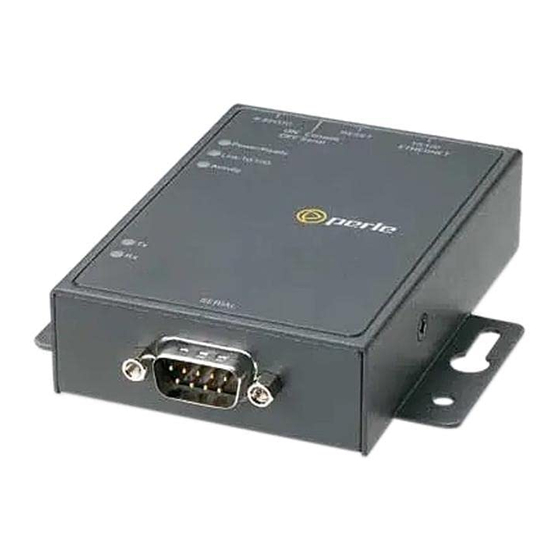
Components
What's Included
- The Device Server
- External power supply*
- A Quick Start Guide
- Warranty Card
- A CD-ROM containing documentation, firmware, DeviceManager, etc.
*NOTE: If the Device Server was purchased in bulk, you have to provide the power supply. See the User's Guide for power supply specifications.
What You Need to Supply
Before you can begin, you need to have the following:
- A serial cable
- An Ethernet 10/100BASE-T cable if you are connecting the Device Server to the network or are powering a P series model (power over Ethernet) through Ethernet
Registering the Device Server
You should register Device Server online at:
http://www.perle.com/support_services/warranty_reg.asp
Powering On the Device Server
Before you attach the Device Server to your network or try to configure it, we suggest that you power it up to verify that it works properly. To power up the Device Server, perform the following steps:
- Plug the external power supply into the Device Server and then into the electrical outlet.
If you have the Power over Ethernet model and want to power the Device Server through the Ethernet cable, attach the Ethernet cable to the Device Server and the Power Source Equipment (PSE). - If the Device Server is working correctly, you should see:
- The Power/Ready LED starts out red
- The Power/Ready LED flashes green while the Device Server boots up
- The Power/Ready LED stays solid green, indicating that it is ready to configure/use
If this test works correctly, you are now ready to begin communicating with your IOLAN Device Server. The last step of the quick installation process is to set an IP address for the Device Server; this is necessary before it can be configured and put into production.
LED Guide
The Device Server LEDs display the following information:
- Power/Ready—(Green/Red) Shows red at power up. If the LED remains red, there is a critical error (see the Troubleshooting chapter of the User's Guide for information on what to do if this happens). Next, the LED should flash green to indicate that the Device Server is booting. Lastly, the LED should stay a solid green to indicate that the Device Server is ready.
- Link/10/100
- Green—10 Mbits
- Yellow—100 Mbits
- Off—no LAN connection
- Activity—Flashes Green for TX or RX data
- Tx—Flashes with transmit serial activity
- Rx—Flashes with receive serial activity
Configuring the Device Server
There are several different methods that can be used to configure the Device Server. The Easy Config Wizard configuration method is described in this section; see the IOLAN DS Family User's Guide (included on the CD-ROM) for other configuration methods for your Device Server model.
Easy Config Wizard
When you insert the CD-ROM into your Windows-based computer, the Easy Config Wizard will launch automatically. You can use the Easy Config Wizard to assign an IP address and configure your Device Server's lines for any of the following:
- *Printers
- Raw TCP (Dir Raw)
- Terminal Management (Dir Telnet)
- Console Management (Rev Telnet)
- *Secure Console Management (Rev SSH)
- Virtual COM Port
*SDS models only
If you want to configure the Device Server for another purpose, install and run the DeviceManager, a complete configuration/management application.
Default admin Password
The first time you try to login to the Device Server, use the following values:
User: admin
Password: superuser.
You should change the admin password to restrict unauthorized access to the Device Server.
What's Next
Now that you have assigned the Device Server an IP address, you are ready to configure the server, lines, users, etc., for your production environment. You can configure the Device Server using any of the following methods:
- DeviceManager, a Windows-based configuration/management application.
- Menu, a windows-like configuration application.
- CLI, a command line interface configuration/management application.
- WebManager, a web browser configuration/management application.
- SNMP, configure/manage the Device Server.
- BOOTP/DHCP, specify configuration information.
About the DeviceManager
The DeviceManager is our flagship configuration application (it can be installed from the CD-ROM) that can be used to assign an IP address to a new Device Server, configure Device Server parameters, view Device Server statistics, and manage a Device Server.
Using IOLAN+ Mode
If you are an existing IOLAN+ user and want to configure the SDS model Device Server using the IOLAN+ interface, type iolan+ at the CLI command prompt. See the User's Guide for more information on this option.
Cabling Diagrams
See the User's Guide for cabling diagrams for each of the connection options.
DB25 Male Pinouts

In the following table, pin 9 (power out), is available in only the SDS1 model:
| Pinout | EIA-232 | EIA-422 | EIA-485 Full Duplex | EIA-485 Half Duplex |
| 1 | Shield | Shield | Shield | Shield |
| 2 (out) | TxD | |||
| 3 (in) | RxD | |||
| 4 (out) | RTS | |||
| 5 (in) | CTS | |||
| 6 (in) | DSR | |||
| 7 | GND | GND | GND | GND |
| 8 (in) | DCD | |||
| 9 | Power out | Power out | Power out | Power out |
| 12 | Power in | Power in | Power in | Power in |
| 13 | CTS- | |||
| 14 | TxD+ | TxD+ | DATA+ | |
| 15 | TxD- | TxD- | DATA- | |
| 18 | RTS+ | |||
| 19 | RTS- | |||
| 20 (out) | DTR | |||
| 21 | RxD+ | RxD+ | ||
| 22 | RxD- | RxD- | ||
| 25 | CTS+ |
The power in pin, pin 12, can be 9-30V DC.
DB25 Female Pinouts

In the following table, pin 9 (power out), is available in only the SDS1 model:
| Pinout | EIA-232 | EIA-422 | EIA-485 Full Duplex | EIA-485 Half Duplex |
| 1 | Shield | Shield | Shield | Shield |
| 2 (in) | RxD | |||
| 3 (out) | TxD | |||
| 4 (out) | CTS | |||
| 5 (in) | RTS | |||
| 6 (in) | DTR | |||
| 7 | GND | GND | GND | GND |
| 8 (in) | DCD | |||
| 9 | Power out | Power out | Power out | Power out |
| 12 | Power in | Power in | Power in | Power in |
| 13 | RTS- | |||
| 14 | RxD+ | RxD+ | DATA+ | |
| 15 | RxD- | RxD- | DATA- | |
| 18 | CTS+ | |||
| 19 | CTS- | |||
| 20 (out) | DSR | |||
| 21 | TxD+ | TxD+ | ||
| 22 | TxD- | TxD- | ||
| 25 | RTS+ |
The power in pin, pin 12, can be 9-30V DC.
RJ45 10-Pin Pinouts

The following table is for a 10-pin RJ45 connector. If you are using an 8-pin connector, then map Pin 1 in the 8-pin connector to Pin 2 in the 10-pin connector table.
| Pinout | EIA-232 | EIA-422 | EIA-485 Full Duplex | EIA-485 Half Duplex |
| 1 | Power In | Power In | Power In | Power In |
| 2 (in) | DCD | |||
| 3 (out) | RTS | TxD+ | TxD+ | TxD+/RxD+ |
| 4 (in) | DSR | |||
| 5 (out) | TxD | TxD- | TxD- | TxD-/RxD- |
| 6 (in) | RxD | RxD+ | RxD+ | |
| 7 | GND | GND | GND | GND |
| 8 (in) | CTS | RxD- | RxD- | |
| 9 (out) | DTR | |||
| 10 | Power Out | Power Out | Power Out | Power Out |
The power in pin, pin 1, can be 9-30V DC.
DB9 Male Pinouts

The following table is for a 9-pin DB9 male connector.
| Pinout | EIA-232 | EIA-422/485 Full Duplex | EIA-485 Half Duplex |
| 1 (in) | DCD | ||
| 2 (in) | RxD | RxD+ | |
| 3 (out) | TxD | TxD+ | TxD+/RxD+ |
| 4 (out) | DTR | ||
| 5 | GND | GND | GND |
| 6 (in) | DSR | RxD- | |
| 7 | RTS | ||
| 8 (in) | CTS | ||
| 9 | TxD- | TxD-/RxD- |
Perle offers free technical support to Perle Authorised Distributors and Registered Perle Resellers.
To access technical support, please visit the Perle website at www.perle.com/support.
Here you will find:
- latest drivers and firmware updates for download
- technical tips
- frequently asked questions
- documentation
- configuration support
- cabling information
- maintenance contract information
- and much more...
If you are unable to find the information you require, please feel free to contact our technical support teams by email at:
USA
Email: ptac@perle.com
Europe
Email: ptacemea@perle.com
Asia
Email: ptacasia@perle.com
Internet
www.perle.com/support_services
IOLAN DS Family
1-Port Quick Start Guide
Part No: 5500160-16
Copyright © Perle Systems Limited, 2005-2006

Documents / Resources
References
Perle | device networking, media conversion, & IoT connectivity
Perle | device networking, media conversion, & IoT connectivity
Perle | device networking, media conversion, & IoT connectivity
Download manual
Here you can download full pdf version of manual, it may contain additional safety instructions, warranty information, FCC rules, etc.
Advertisement


Need help?
Do you have a question about the IOLAN DS and is the answer not in the manual?
Questions and answers