Table of Contents
Advertisement
Quick Links
Advertisement
Table of Contents

Subscribe to Our Youtube Channel
Related Manuals for Perle IOAN DS1


Summary of Contents for Perle IOAN DS1
- Page 1 IOLAN DS Family DS1/TS2 User’s Guide Version 1.8 Part #5500162-18 November 2006...
- Page 2 Markham, ON Canada L3R 0E1 Perle reserves the right to make changes without further notice, to any products to improve reliability, function, or design. Perle, the Perle logo, and IOLAN are trademarks of Perle Systems Limited. Microsoft, Windows 98, Windows NT, Windows 2000, Windows Server 2003, Windows XP, and Internet Explorer are trademarks of Microsoft Corporation.
-
Page 3: Table Of Contents
Making a Technical Support Query ............21 Who To Contact ................. 21 Have Your Product Information Ready ..........21 Making a support query via the Perle web page ........ 21 Repair Procedure..................22 Feedback on this Manual............... 22 Chapter 1 Introduction............23 About the IOLAN Device Server .......... - Page 4 Table of Contents Typical Applications Summary ..........25 Managing the Device Server ..............25 Managing/Accessing devices attached to the Device Server..... 25 Network Security..................26 Chapter 2 Installation............27 Introduction.................27 IOLAN Device Server Components...........27 What’s Included ..................27 What You Need to Supply ..............27 Available Accessories ................
- Page 5 Table of Contents Wiring I/O Diagrams..............34 Digital I/O....................34 Digital Input Wet Contact ..............34 Digital Input Dry Contact ..............35 Digital Output Sink ................35 Digital Output Source ................. 35 Analog Input.................... 36 Current ....................36 Voltage ....................36 Temperature Input ..................
- Page 6 Table of Contents Chapter 3 Configuration Methods ........51 Introduction.................51 DeviceManager ................51 WebManager ................52 Using the WebManager ................52 CLI....................52 Menu ....................52 Accessing the Menu ................52 Menu Conventions.................. 53 DHCP/BOOTP................53 SNMP ...................54 Chapter 4 Configuring the Device Server .......55 Introduction.................55 Configuring the Device Server ..........55 General Device Server Configuration ...........
- Page 7 Table of Contents Machine To Machine Connections ........... 62 Users Connecting to Serial Devices ........62 Users Connecting to the LAN ........... 62 Connecting To the Device Server ............63 Connecting Through the Device Server ..........63 Setting Up Lines................. 63 DSLogin....................
- Page 8 Table of Contents Downloading Terminal Definitions ...........71 Creating Terminal Definition Files............71 TFTP Configuration ..............73 Resetting Configuration Parameters ........73 Lost Admin Password..............73 DHCP/BOOTP................73 DHCP/BOOTP Parameters ..............74 Creating Custom Applications ..........74 I/O Model Features ..............74 Failsafe Timer..................74 Alarms...................... 75 UDP ......................
- Page 9 Table of Contents Calibrating Analog Input................ 86 Calibrating Voltage................86 Calibrating Current ................86 Calibrating Temperature Input .............. 86 Calibrating Thermocouple ..............86 Calibrating RTD.................. 86 Chapter 5 Using the DeviceManager .......87 Introduction ................87 Starting a New Session ............. 87 Managing a Device Server ..............
- Page 10 Table of Contents Configuring Lines...............95 Advanced Line Settings ................. 97 Service Settings ..................99 DSLogin....................99 Raw Settings ..................100 Telnet Settings.................. 100 BIDIR Settings .................. 101 UDP Settings ..................102 VModem Settings ................103 Server Tunnel Settings ..............103 Client Tunnel Settings ..............
- Page 11 Table of Contents Configuring the Network ............125 Configuring Hosts ................125 Configuring SNMP................126 Configuring TFTP ................. 127 Configuring Gateways ................. 127 Configuring Syslog ................128 Configuring Administration Tasks ......... 129 Configuring Bootup Files ..............129 Configuring the MOTD File ..............129 I/O Status/Control ..............
- Page 12 Table of Contents Chapter 6 Command Line Interface.......137 Introduction................137 CLI Conventions ...............137 Command Syntax..................137 Command Shortcuts................138 Command Options................138 Server Commands..............139 Server Commands ................139 Set Custom-App ................139 Set Server..................139 Set Service ..................141 Show Custom-App................141 Show Modbus...................
- Page 13 Table of Contents Show Termtype ................147 Start....................148 Telnet ....................148 Version ..................... 149 Configuring Users ................149 Add User ..................149 Delete User ..................149 Set Default User................150 Set User ................... 152 Set User Session ................154 Show Default User ................
- Page 14 Table of Contents Network Commands..............169 SNMP Commands ................. 169 Add Community ................169 Add Trap................... 169 Delete Community ................170 Delete Trap..................170 Set SNMP..................170 Show SNMP ..................170 TFTP Commands ..................171 Set Server TFTP................171 Hosts Commands ................. 171 Add Host...................
- Page 15 Table of Contents TFTP File Transfer Commands ............176 Netload..................... 176 Netsave .................... 177 MOTD Commands ................177 Set MOTD ..................177 Show MOTD..................178 Statistic Commands ..............178 Configuration Statistics ............... 178 Show Netstat..................178 Show Modbus Statistics ..............178 Show Netstat Statistics ..............
- Page 16 Table of Contents I/O Channel Control Commands............192 Digital Output..................192 Digital Input..................192 Relay ....................192 Analog Input ..................192 Calibrating Analog Input (Analog/Temperature)........ 193 Calibrate Analog ................193 Reset Calibration ................193 Appendix A Troubleshooting .........195 Introduction................195 Hardware Problems..............195 Communication Issues ............195 DeviceManager Problems............196 Host Problems ................196...
- Page 17 Table of Contents Appendix B Utilities ............199 Introduction ................199 TruePort ..................199 API I/O Access Over TruePort ..........200 API Request Format ................200 API Response Format ................200 Error Codes..................201 Appendix C Accessories ..........203 Introduction ................203 Starter Kit (Adapters/Cable)............
- Page 18 Table of Contents IOLAN Device Server User’s Guide, Version 1.8...
-
Page 19: Preface
Preface About This Book This guide provides the information you need to: configure the Device Server incorporate the Device Server into your production environment Intended Audience This guide is for administrators who will be configuring the Device Server. Some prerequisite knowledge is needed to understand the concepts and examples in this guide: If you are using an external authentication application(s), working knowledge of the authentication application(s). -
Page 20: Typeface Conventions
Typeface Conventions Typeface Conventions Most text is presented in the typeface used in this paragraph. Other typefaces are used to help you identify certain types of information. The other typefaces are: Typeface Example Usage At the C: prompt, type: This typeface is used for code examples and system-generated output. -
Page 21: Contacting Technical Support
Perle offers free technical support to Perle Authorised Distributors and Registered Perle Resellers. If you bought your product from a registered Perle supplier, you must contact their Technical Support department; they are qualified to deal with your problem. Have Your Product Information Ready... -
Page 22: Repair Procedure
Contacting Technical Support Repair Procedure Before sending a Device Server for repair, you must contact your Perle supplier. If, however, you bought your product directly from Perle you can contact directly. Customers who are in Europe, Africa or Middle East can submit repair details via a website form. -
Page 23: Chapter 1 Introduction
Introduction Chapter 1 About the IOLAN Device Server The Device Server is an ethernet communications/terminal server that allows serial devices to be connected directly to LANs. The Device Server can connect to a wide range of devices including: Terminals for multi-user UNIX systems Data acquisition equipment (manufacturing, laboratory, scanners, etc.) Retail point-of-sale equipment (bar coding, registers, etc.) PCs using terminal emulation... -
Page 24: Device Server Features
SSH, SSL, port buffering, email alerts, RIP, DNS/WINS, plus much more. This model has an EIA-232 interface. Rack mount models have a dedicated Console port. This model comes equipped with PCI interface (supports the Perle PCI modem card), gigabit support, dual Ethernet, and can have dual AC power. -
Page 25: Security
Supported Products/Versions Security The Device Server security features include: Supervisory and port (line) password. Port locking. Per user access level assignment. Logging via Syslog. Idle port timers, which close a connection that has not been active for a specified period of time. Ability to individually disable daemons/services that won’t be used by the Device Server. -
Page 26: Network Security
Typical Applications Summary Network Security The Device Server provides a comprehensive suite of security features to allow an organization to implement robust security planning to prevent unauthorized access. These include trusted host filtering and the ability to disable individual services. IOLAN Device Server User’s Guide, Version 1.8... -
Page 27: Chapter 2 Installation
Installation Chapter 2 Introduction This chapter tells you what is packaged with your IOLAN Device Server, how to power up the Device Server to make sure it works correctly, and how to assign the Device Server an IP address through the LAN. IOLAN Device Server Components What’s Included When you open your IOLAN Device Server package, you should have the following components:... -
Page 28: Getting To Know Your Device Server
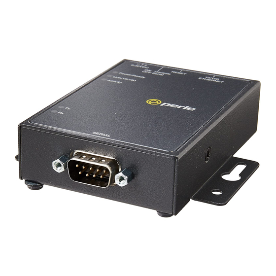
Getting to Know Your Device Server Getting to Know Your Device Server This section describes the components found on the Device Server. Console/Serial Reset to Factory Mode Switch Defaults Power Supply Ethernet Interface Power LAN Connection LAN Activity Serial Activity Serial Connection This section describes the components found on the TS2 Device Server model. -
Page 29: Led Guide
Powering Up the Device Server LED Guide The Device Server LEDs display the following information: Power/Ready—(Green/Red/Yellow) Shows red at power up. If this LED remains red, indicates that there is a critical error (return to factory). Flashes green to indicate that the Device Server is booting. -
Page 30: I/O Models
Powering Up the Device Server I/O Models If you are providing a power supply for a desktop Device Server I/O model, your power supply must meet the following requirements: Output between 9-30V DC and a minimum of 600mA current. Note: The maximum load for the Relay channel is 1A @ 30VDC or 0.5A @ 120VAC. -
Page 31: Setting Jumpers
Setting Jumpers Setting Jumpers The Device Server contains jumpers that you might need to set before you configure it and put it into production. You can set the power out pin (not on the DB9 model) to a fixed 5V DC output or to the external adapter output;... -
Page 32: Device Server Db9
Setting Jumpers Device Server DB9 To change the settings, do the following: Unplug the Device Server from the electrical outlet and disconnect everything from the box. Open the case by unscrewing the two side screws, one on each side, and lifting off the top of the case. -
Page 33: Digital I/O Module
Setting Jumpers Digital I/O Module Device Servers that have Digital I/O have an input/output jumper that must be set for each channel and must match the software configuration for each channel. Depending on the model, the placement of the Digital I/O board can change, so the diagram below shows how to set jumper for any Digital board.To change the settings, do the following: Detach the Device Server from the electrical power source and disconnect everything from the box. -
Page 34: Analog Input Module
Wiring I/O Diagrams Analog Input Module Device Servers that have Analog input have a voltage/current jumper that must be set for each channel and must match the software configuration for each channel. To change the settings, do the following: Detach the Device Server from the electrical power source and disconnect everything from the box. -
Page 35: Digital Input Dry Contact
Wiring I/O Diagrams Digital Input Dry Contact If you are using a dry contact for your Digital input, for channel D1 connect one wire to D1 and the other wire to COM. The power source is supplied by the COM (common) connector. Power Source Digital Output Sink... -
Page 36: Analog Input
Wiring I/O Diagrams Analog Input Make sure the Analog jumpers support the software setting; see Analog Input Module on page 34 jumper settings. Current To connect channel A1 with a 2-wire shielded cable, connect the positive wire to A1+, the negative wire to A1-, and optionally the shield to GND. -
Page 37: Rtd 2-Wire
Wiring I/O Diagrams RTD 2-Wire In a 2-wire RTD configuration, connect the excite wire to A1-, the return wire to A1+, and jumper the sense wire from A1s with a insulated wire going to A1+. sense RTD 3-Wire In a 3-wire RTD configuration, connect the return wire to A1+, the excite wire to A1-, and the sense wire to A1s. -
Page 38: Normally Closed Contact
Setting an Initial IP Address Normally Closed Contact To connect relay channel R1 for a circuit that is normally active, connect one wire to the COM (common) connector and one wire to the NC (normally closed) connector. Setting an Initial IP Address This section describes the different methods you can use to set the Device Server IP address. -
Page 39: Using Devicemanager
Setting an Initial IP Address Using DeviceManager To use the DeviceManager, you must first install it on a Windows 98/2000/NT/ME/Server 2003/XP operating system (Windows NT requires Service Pack 4 or later) that resides in the same network as the Device Server. The DeviceManager installation wizard can be found on the CD-ROM included in the Device Server package. -
Page 40: Using A Direct Connection
Setting an Initial IP Address Using a Direct Connection You can connect to the Device Server using a PC with a terminal emulation package, such as HyperTerminal or a terminal. Connect the Device Server to your PC or dumb terminal. Make sure the dip switch is in Console mode (this sets the Device Server serial port to EIA-232). -
Page 41: Using Arp-Ping
Setting an Initial IP Address Type the following command: save The the following command: reboot When the Device Server reboots, it will automatically poll for an IP address from the DHCP/BOOTP server. If you have a Device Server with dual Ethernet, each Ethernet connection will automatically be assigned an IP address, you can access the Device Server through either IP address. -
Page 42: Pinouts
Pinouts Pinouts DB25 Male This section defines the pinouts for the DB25 male connection used on the 1-port Device Server. Pin 1 Pin 13 Pin 14 Pin 25 The following table provides pinout information: EIA-232 EIA-422 EIA-485 EIA-485 Pinout Full Duplex Half Duplex Shield Shield... -
Page 43: Db25 Female
Pinouts DB25 Female This section defines the pinouts for the DB25 female connection used on the 1-port Device Server. Pin 13 Pin 1 Pin 25 Pin 14 The following table provides pinout information: EIA-232 EIA-422 EIA-485 EIA-485 Pinout Full Duplex Half Duplex Shield Shield... -
Page 44: Rj45
Pinouts RJ45 This section defines the pinouts for the RJ45 connection used on the DS and TS Device Server. The TS Device Server does not support power in, so use the 8-pin mappings for this model. These pinouts do not apply to I/O models. Pin 1 Pin 10 The following table provides pinout information:... -
Page 45: Db9 Male I/O
Pinouts DB9 Male I/O This section defines the pinouts for the DB9 male connection used on the 1-port Device Server I/O models. The following table provides pinout information: Pinout EIA-422/485 EIA-485 9-pin EIA-232 Full Duplex Half Duplex 1(in) 2 (in) RxD+ 3 (out) TxD-... -
Page 46: Eia-232 Cabling Diagrams
EIA-232 Cabling Diagrams EIA-232 Cabling Diagrams This section shows how to create EIA-232 cables that are compatible with the Device Server. Terminal DB25 Connector The following diagrams show how the null modem cable should be configured when connecting to a terminal DB25. -
Page 47: Rj45
EIA-232 Cabling Diagrams RJ45 Terminal DB25 IOLAN RJ45 (DTE) 10-pin 8-pin (DSR) 20 (DTR) (RTS) 5 (CTS) (TxD) 3 (RxD) (RxD) 2 (TxD) (GND) 7 (GND) (CTS) 4 (RTS) (DTR) 6 (DSR) DB9 Male IOLAN DS1 Terminal DB25 DB9 Male (DTE) 3 (TxD) 3 (RxD) -
Page 48: Modem Db25 Connector
EIA-232 Cabling Diagrams Modem DB25 Connector The following diagrams show how a standard straight through cable should be configured when connecting to a DB25 modem. DB25 Male IOLAN DS1 Modem DB25 DB25 (DTE) (DCE) 2 (TxD) 2 (RxD) 3 (RxD) 3 (TxD) 4 (RTS) 4 (CTS) -
Page 49: Db9 Male
EIA-232 Cabling Diagrams DB9 Male IOLAN DS1 Modem DB25 DB9 Male (DCE) 1 (DCD) 8 (DCD) 2 (RxD) 3 (TxD) 3 (TxD) 2 (RxD) 4 (DTR) 20 (DTR) 5 (GND) 7 (GND) 6 (DSR) 6 (DSR) 7 (RTS) 4 (CTS) 8 (CTS) 5 (RTS) - Page 50 EIA-232 Cabling Diagrams IOLAN Device Server User’s Guide, Version 1.8...
-
Page 51: Chapter 3 Configuration Methods
Configuration Methods Chapter 3 Introduction This chapter provides information about the different methods you can use to configure the Device Server. Before you can configure the Device Server, you must assign an IP address to the Device Server. You can assign an IP address to the Device Server using one of the following methods: Using the DeviceManager as described in Using DeviceManager on page Using ARP-Ping as described in... -
Page 52: Webmanager
WebManager WebManager The WebManager is a web-browser based method of configuring/managing a Device Server. To access a Device Server through the WebManager, open up your web browser and type in the IP address of the Device Server that you want to manage/configure. A login screen will appear.ype in the Admin password. -
Page 53: Menu Conventions
DHCP/BOOTP Menu Conventions You select an option from the Menu by using the keyboard up and down arrows to navigate the list. When the menu item you want to access is highlighted, press the key to either get to the next Enter list of options or to get the configuration screen, depending on what you select. -
Page 54: Snmp
CD-ROM into your SNMP manager. Connect to the Device Server through your SNMP manager using its IP address to configure/manage the Device Server. Expand the PERLE-IOLAN-DS1-MIB folder to see the Device Server’s parameter folders. Below is an example of the configurable parameters under the ServicesInfo folder. -
Page 55: Chapter 4 Configuring The Device Server
Configuring the Device Server Chapter 4 Introduction This chapter provides general information about configuring the Device Server for your production environment. Although this chapter is not specific to any configuration method, there should be enough information that you can apply the information to any of the configuration methods. When you are configuring the Device Server, remember that none of your configuration changes will be permanent until you submit/apply your changes, save to FLASH, and reboot the Device Server. -
Page 56: Trueport
Configuring the Device Server TruePort The TruePort utility acts as a com port redirector that allows applications to talk to serial devices across a network as though the serial devices were directly attached to the server. For Device Server I/O models, you can also monitor and control I/O through the TruePort client. You can map the baud rate of the host COM port to a higher baud rate for the serial line that connects the serial device and the Device Server. -
Page 57: Modbus Configuration
Modbus Configuration Modbus Configuration This sections provides a brief overview of the steps required to configure a Device Server for your Modbus environment. You can read the Modbus Gateway Settings on page 58 Modbus Line Settings on page 59 sections for more specific information about the Modbus settings. Overview Configuring a Master Gateway To configure a Master Gateway (Modbus Master resides on the serial side of the Device Server), do... -
Page 58: Modbus Gateway Settings
Modbus Configuration Modbus Gateway Settings The scenarios in this section are used to illustrate how the Modbus Gateway settings are incorporated into a Modbus device environment. Depending on how your Modbus Master or Slave devices are distributed, the Device Server can act as both a Slave and Master Gateway(s) on a multiport Device Server or as either a Slave or Master Gateway on a single port Device Server. -
Page 59: Modbus Line Settings
Modbus Configuration Modbus Line Settings Modbus Master Settings When you have Modbus Masters on the serial side of the Device Server, configure the Line as a Modbus Master. If you also have a Modbus serial Slave on the same serial network as the serial Modbus Master that communicates with that serial Master, do not define its UID in the Remote Slave IP Mappings settings, or the Modbus serial Slave may not function properly. -
Page 60: Example Scenario
Modbus Configuration Example Scenario The following example describes the settings that you would configure to set up a Modbus environment on a multiport Device Server, where the Modbus Master resides on a serial port/line connected to the Device Server. This scenario assumes two things, that the (the Service ModbusD Modbus daemon) is enabled and that the default... - Page 61 Modbus Configuration The Device Server will send a request and expect a response from a Modbus Slave with an IP Address of 10.10.10.11 on Port 502 with UID 22 and from Modbus Slave with and IP Address of 10.10.10.12 on Port 502 with UID 23 (remember when is set to , the Device Range Mode...
-
Page 62: Machine To Machine Connections
Machine To Machine Connections Machine To Machine Connections If you are using the Device Server to connect two hosts, allowing data to flow freely between them, you just need to configure the Server and the Line User required). In the following example, the serial device is a security Card Reader that needs to transmit and receive information to/from a host on the network that maintains the Card Reader’s application every time an employee uses an access card to attempt to gain entry to the company. -
Page 63: Connecting To The Device Server
Setting Up Lines Connecting To the Device Server When a user connects to the Device Server, that user is authenticated and is usually set up with predefined sessions or given the opportunity to configure a to access any host using Free Session any protocol (must have a Level... -
Page 64: Direct/Silent/Reverse Connections
Setting Up Lines Direct/Silent/Reverse Connections Direct connections bypass the Device Server, enabling the user to log straight into a specific host. A direct connection is recommended where a user logging in to the Device Server is not required. It is also recommended where multiple sessions are not a requirement. -
Page 65: Udp
Setting Up Lines When you configure , you are setting up a range of IP addresses and a port number that you will use to send UDP data to or receive UDP data from. For example: The UDP configuration window, taken from the DeviceManager, is configured to: UDP Entry 1 All hosts that have an IP address that falls within the range of 172.16.1.1... -
Page 66: Serial Tunnel Settings
Setting Up Users Serial Tunnel Settings The purpose of the serial Line Service Client/Server Tunnel is to allow two Device Servers that are connected back-to-back over Ethernet to virtually link two serial ports, based on RFC 2217. The serial device that initiates the connection is the and the recipient is the Client Tunnel Server Tunnel... -
Page 67: User Levels
Setting Up Users User Levels There are four , and . Setting up users is only User Levels Admin Normal Restricted Menu necessary when the users are actually connecting to the Device Server. Oftentimes, the Device Server is used as a gateway to a network and the user never actually logs into the Device Server itself. Users who do log into the Device Server ( set to set to... -
Page 68: Reverse Sessions And Multisessions
Setting Up Users Reverse Sessions and Multisessions (2 Port+ only) The interaction between reverse sessions and multisessions is somewhat complex, so the definition of each parameter is provided to give you a context for their interaction. Reverse Session—The definition of a Reverse Session is a TCP connection to a TCP port (defined in the Line configuration as the DS Port ) on a line that is configured for... -
Page 69: Configuring Network Options
Device Server; this can be done in the DeviceManager, WebManager, CLI, or Menu. You must then load the perle-ds1.MIB (found on the CD-ROM packaged with the Device Server) file into your SNMP manager before you connect to the Device Server. -
Page 70: Loading A Supplied Language
Language support Loading a Supplied Language This section describes how to download a language file using the CLI, since it is the least intuitive method. French and German language files are provided on the supplemental CD. To load one of the supplied languages into the Device Server, so the Menu, CLI and WebManager fields appear in another language, do the following: Open the supplemental CD and identify the language file, either Iolan_ds_French.txt... -
Page 71: Software Upgrades And Language Files
Downloading Terminal Definitions Software Upgrades and Language Files If you receive a software upgrade for the Device Server, the language files supplied on the supplemental diskette/CD might also have been updated. We will endeavour to provide a list of those changes in another text file on the same supplemental CD. - Page 72 Downloading Terminal Definitions Rename and copy the file to the directory specified at step 4. using the command where is greater than or equal to 1; (for example, infocmp termfile > termn ). Make sure the file has global read and execute permission for its infocmp wy50 >...
-
Page 73: Tftp Configuration
TFTP Configuration TFTP Configuration TFTP can be configured for two unique transfer operations: Between the DeviceManager and a Device Server. This configuration is accessed by selecting Tools, Options from the DeviceManager’s tool bar. You can specify the number of times the DeviceManager’s TFTP server retries a file transfer to a Device Server, how long the TFTP process will wait (timeout) before retrying to transfer a file, and the UPD port that will be used for the file transfer between the DeviceManager and the Device Server. -
Page 74: Dhcp/Bootp Parameters
(IPv4 or IPv6), and file name of a termcap file for a specific terminal type. Creating Custom Applications You can create custom applications for the Device Server by using the Perle SDK. See the SDK Programmer’s Guide (the SDK and guide are found on the Perle website at ) for information about the functions that are www.perle.com/downloads/index.shtml... -
Page 75: Alarms
I/O Model Features Alarms Analog and Temperature input models support an Alarm mechanism in which you can specify up to five severity levels of alarm triggers and clear levels; the alarm triggers/clear levels can activate in either increasing or decreasing severity levels. The Digital input supports an Alarm mechanism based on a trigger of either active input or inactive input and can be cleared either manually or automatically (when the trigger condition goes inactive or active, respectively). -
Page 76: Udp Unicast Example
I/O Model Features Digital/Relay Data The digital data is in bit format, 1 meaning On and 0 (zero) meaning Off. Each channel has its own bit, in least significant bit order. Length *Data Data (1 Byte, one bit for each channel) Exists 2 Bytes 1 Byte... -
Page 77: Modbus Serial Application Connected To The Network
I/O Model Features Modbus Serial Application Connected to the Network If you want to access the I/O from a LAN connection, you can install TruePort on the PC running the Modbus serial application as described in TruePort on page 80 and connect to the Device Server over the network. -
Page 78: A4/T4 Registers
I/O Model Features A4/T4 Registers The following registers are supported by the Device Server A4 and T4 input models: Data Model A1/T1 A2/T2 A3/T3 A4/T4 Holding Registers: MB_REG_HR_AI_CLEAR_ALARM_LATCH 2049 2050 2051 2052 MB_REG_HR_AI_CLEAR_MAX 2113 2114 2115 2116 MB_REG_HR_AI_CLEAR_MIX 2177 2178 2179 2180 Input Registers:... -
Page 79: D4/D2R2 Registers
I/O Model Features Data Model D1/R1 D2/R2 R/W MB_REG_IR_MIN_RAW 2087 2119 2151 2183 ----- ----- MB_REG_IR_MAX_RAW 2088 2120 2152 2184 ----- ----- MB_REG_IR_ALARM_LEVEL 2089 2121 2153 2185 ----- ----- *For DI alarm state read will get state, write will clear alarm. D4/D2R2 Registers The following coils and registers are supported by the Device Server D4 and D2R2 I/O models: Data Model... -
Page 80: Trueport
If you have a custom application that talks to a serial port, you can use TruePort as a virtual serial port to communicate with the Device Server over the network to access I/O data using the Perle API. You also have the option of enabling SSL as a security option to encrypt the data that is communicated between the Device Server and the host machine (SSL/TLS must be configured in the Server settings and on the TruePort host). -
Page 81: Digital Channels
I/O Model Features Digital Channels You can configure the Digital I/O channels for either input or output, making the Device Server flexible in your production environment. Jumpers must be set to correspond with the software setting of either Input or Output; see Digital I/O Module on page 33 for jumper settings. -
Page 82: Digital Output
When one of the industrial freezer doors are left open for more than five minutes, the Monitoring Application (using the Perle API) starts the Digital output sink, causing the strobe light on top of the offending freezer to activate. -
Page 83: Temperature Channels
I/O Model Features Temperature Channels Temperature input channels monitor RTD or thermocouple temperature sensors. You can also configure severity alarms that can send an email, a syslog message, and/or an SNMP when an alarm is triggered or cleared; See Alarms on page 75 for more information about the alarms. -
Page 84: Analog Channels
(monitored by an Analog channel) a syslog message is sent to the Monitoring Application. The Monitoring Application then sends a command to the Device Server via the Perle API that causes the Relay channel to activate an internal freezer dehumidifier. The relay is turned off when the Analog channel sends a clear syslog message to the Monitoring Application and the Relay channel is deactivated. -
Page 85: Relay Channels
I/O Model Features Relay Channels Relay output channels work as a physical on/off switch, and are used to drive higher voltage devices with a lower controlling voltage. You can configure the following Relay output channel options: You can choose to manually activate/deactivate the Relay output. You can choose to manually activate/deactivate the Relay output and then specify that the Relay output will either pulse (you get to specify the active and inactive pulse times) continuously or for a specified number of pulse counts. -
Page 86: Calibrating Analog Input
I/O Model Features Calibrating Analog Input To calibrate an Analog input channel, read the section that applies to the type of input you are calibrating. Note that calibration will be done for the active channel configuration; for example, if Channel A1 is set to voltage, you cannot calibrate it for current. The voltage range configured for this channel will also dictate what is being calibrated. -
Page 87: Chapter 5 Using The Devicemanager
Using the DeviceManager Chapter 5 Introduction This chapter provides information about configuring/managing the Device Server using the DeviceManager. It is assumed that the DeviceManager has already been installed; if you still need to install the DeviceManager, see Using DeviceManager on page Starting a New Session When you start the DeviceManager application, the New Session window is displayed. -
Page 88: Managing A Device Server
Starting a New Session Managing a Device Server You can connect to Device Servers or assign a temporary IP address to a new Device Server. Whenever you connect to a Device Server through the DeviceManager, you connect as the Admin user and must supply the password for the Admin user. -
Page 89: Assigning A Temporary Ip Address To A New Device Server
Starting a New Session Assigning a Temporary IP Address to a New Device Server If your network does not use DHCP/BOOTP, you can temporarily assign an IP address to a Device Server that is connected to your local network segment, for the purpose of connecting to it and downloading a configuration file (containing a permanent IP address). -
Page 90: Creating A New Device Server Configuration
Connecting to a Device Server Creating a New Device Server Configuration If you selected the New Configuration radio button, the New Configuration window is displayed. Select the Device Server model for which you want to create a new configuration file. Opening an Existing Configuration File If you selected the radio button, a browse window is opened so you can select... -
Page 91: Managing A Device Server
Managing a Device Server Managing a Device Server Once you are connected to a Device Server, you can edit its configuration, download a new configuration, save the configuration to file, perform administrative tasks, and view statistics about the Device Server and its network environment. DeviceManager Work Flow When you connect to a Device Server, the Device Server’s configuration is automatically uploaded to the Device Server. -
Page 92: Configuring The Server
Configuring the Server Configuring the Server The following sections describe how to configure the Device Server’s server parameters. Configuring the Main Server Window When you select from the navigation panel, the following Server Server Configuration Server window is displayed. Enter values in the Device Server parameters that you need for your production environment. Server Server Name You must supply a name for the Device Server. -
Page 93: Configuring Advanced Server Settings
Configuring the Server Syslog Syslog client process in the Device Server. DHCP/BOOTP DHCP/BOOTP client process in the Device Server. By default, this is disabled/off. If this is enabled, the server IP address parameter is disabled. Configuring Advanced Server Settings In the Server window, the following window is displayed when you click the Advanced button. Configure the appropriate parameters: OEM Login When set, and a custom language file is in use, the login prompt will use the... -
Page 94: Configuring Trueport Baud
100 Mbps Half Duplex 100 Mbps Full Duplex Custom App You can create a custom application that can run on the Device Server using the Perle SDK. Configure the following parameter: Program The name of the SDK program executable that has been already been... -
Page 95: Configuring Lines
Configuring Lines Configuring Lines When you configure the Device Server Line , you are specifying how the port will be used and accessed. You can always make changes to parameters, click the button, and then select Line Apply to test your changes. However, you still must select Tools Kill Line Tools... - Page 96 Configuring Lines Stop Bits Specifies the number of stop bits that follow a byte. Flow Control Defines whether the data flow is handled by the software ( Soft ), hardware Hard Both , or None Single Character When enabled, causes the Device Server to process every character as it comes Interrupt in, as opposed to buffering the characters before processing;...
-
Page 97: Advanced Line Settings
Configuring Lines Advanced Line Settings You can configure these advanced settings for a line. Configure the appropriate parameters: Pages line service, this is the number of video pages the terminal DSLogin supports. Valid values are 1-7. The default is pages. User line service, makes this a line that is dedicated to the specified DSLogin... - Page 98 Configuring Lines Break Specifies how a break is interpreted: None—The Device Server ignores the break key completely and it is not passed through to the host. This is the default setting. Local—The Device Server deals with the break locally. If the user is in a session, the break key has the same effect as a hot key.
-
Page 99: Service Settings
Configuring Lines Hotkey Prefix The prefix that a user types to lock a line or redraw the Menu. The default value is , which corresponds to ) (hex value 02 would be hex 01 Ctrl-a Ctrl-b (^b), etc.): —(Lowercase L) Locks the line until the user unlocks it. The user is ^a l prompted for a password (any password, excluding spaces) and locks the line. -
Page 100: Raw Settings
Configuring Lines Raw Settings When the is set to , data is sent through the connection in its Line Service Direct Silent Raw original format. This raw TCP/IP connection is initiated from the Device Server to the configured host. Configure the following parameters: Host Name The name of the target host. -
Page 101: Bidir Settings
Configuring Lines Interrupt Defines the interrupt character. Typing the interrupt character interrupts the current process. This value is in hexadecimal with a default value of (ASCII value Quit Defines the quit character. Typing the quit character closes and exits the current telnet session. -
Page 102: Udp Settings
Configuring Lines UDP Settings When the is set to , the Device Server processes UDP packets according to the Line Service UDP settings. Configure the following parameters: Start IP Address The first host IP address in the range of IP addresses (for IPV4 or IPV6) that the Device Server will listen for messages from and/or send messages to. -
Page 103: Vmodem Settings
Configuring Lines VModem Settings When the is set to , the Device Server acts as a virtual modem. After a virtual Line Service VModem modem connection is established, data will flow in both directions in its original format. Configure the following parameters: Host Name The target host name. -
Page 104: Client Tunnel Settings
Configuring Lines Client Tunnel Settings The purpose of the serial is to allow two Device Servers that are Line Service Client/Server Tunnel connected back-to-back over Ethernet to virtually link two serial ports. The serial device that initiates the connection is the Client Tunnel and the recipient is the Server Tunnel... -
Page 105: Modbus Master Settings
Configuring Lines Modbus Master Settings This window configures the parameters for Modbus Masters on the serial side of the Device Server. You can also choose to transmit the Modbus Master data encrypted via SSL/TLS. See Modbus Configuration on page 57 for more information about how to configure the Device Server for a Modbus environment. -
Page 106: Remote Ip Slave Mappings
Configuring Lines Remote IP Slave Mappings This window allows you to configure all the Modbus Slaves, which reside on the Ethernet/TCP side of the Device Server, that will be receiving messages from the Modbus Master. See Modbus Configuration on page 57 for more information about how to configure the Device Server for a Modbus environment. -
Page 107: Custom App Settings
Configuring Lines Custom App Settings You can create a custom application that can run on a specific serial line in Device Server using the Perle SDK. Configure the following parameter: Program The name of the SDK program executable that has been already been... -
Page 108: Trueport Settings
Configuring Lines TruePort Settings When the is set to , data is sent through the connection in its original format. Line Service TruePort This raw TCP/IP connection can be initiated from the Device Server to the configured host or from the host to the Device Server, depending on the settings. -
Page 109: Packet Forwarding
Configuring Lines Packet Forwarding The Packet Forwarding feature allows you to control how the data coming from a serial device is packetized before forwarding the packet onto the LAN network. Configure the following parameters: Packet Definition This section allows you to set a variety of packet definition options. The first criteria that is met causes the packet to be transmitted. - Page 110 Configuring Lines Frame Definition This section allows you to control the frame that is transmitted by defining the start and end of frame character(s). If the internal buffer (1024 bytes) is full before the EOF character(s) are received, the packet will be transmitted and the EOF character(s) search will continue.
-
Page 111: Configuring Modems
Configuring Lines Configuring Modems You need to configure a modem if there is a modem connected to the Device Server. Configure the following parameters: Modem Name The name of the modem. Do not use spaces. Modem The initialisation string of the modem; see your modem’s documentation. Initialisation String... -
Page 112: Configuring I/O
Configuring I/O Configuring I/O This configuration entry will appear in the DeviceManager only when connected to a Device Server that supports I/O or when an I/O model configuration is selected. Global Settings The I/O Global Settings enable/disable options that support all I/O channels on your Device Server. Temperature Settings Temperature Scale Select the temperature scale that will be used to display temperature data, either Fahrenheit or Celsius. -
Page 113: Modbus Settings
These TruePort settings pertain specifically to using TruePort to allow serial Modbus Masters to access Device Server I/O data over the network or allowing a serial application to access the Device Server I/O data over the network using the Perle API (see API I/O Access Over TruePort on page for more information). - Page 114 Configuring I/O The I/O UDP settings window allows you to configure the UDP broadcast recipients. Configure the following parameters: UDP Entry When enabled, broadcasts I/O status (data) to the specified range of IP addresses. Start IP Address The first host IP address in the range of IP addresses (for IPV4 or IPV6) that the Device Server will listen for messages from and/or send messages to.
-
Page 115: Channels
Configuring I/O Channels Digital Output When the channel is set for Digital output, either voltage is applied to the channel or the channel is grounded. Note that the internal jumpers must match the software setting and must be set to Output (by default, they are set to Input);... -
Page 116: Digital Input
Configuring I/O Pulse Mode When the , you can have it pulse in a manner or Output Pulse Continuous specify a pulse (each count consists of an active/inactive sequence). The Count default is Continuous Pulse Count The channel output will pulse for the specified number of times; each count consists of an active/inactive sequence. - Page 117 Configuring I/O Invert Signal Inverts the actual condition of the I/O signal in the status; therefore, an inactive status will be displayed as active. Trigger When the trigger condition is met, triggers the specified alarm action. Triggers can be: Disabled—No alarm settings. This is the default. Inactive—When the expected Digital input is active, going inactive will trigger an alarm.
-
Page 118: Relay
Configuring I/O Relay Relay channels can open or close a contact for a higher voltage circuit using a lower level control voltage. Configure the following parameters: Enable Channel Enables the channel, allowing the settings to become active. Description Provide a description of the channel, making it easier to identify. The channel description can be up to 20 characters. -
Page 119: Analog
Configuring I/O Analog Analog channels monitor current/voltage input. Note that the internal jumpers must match the software setting (by default, they are set to Current); see Analog Input Module on page 34 to find out how to set the internal jumpers. Configure the following parameters: Enable Channel Enables the channel, allowing the settings to become active. -
Page 120: Basic Alarm Settings
Configuring I/O Basic Alarm Settings The basic Analog Alarm Settings window allows you to configure one severity alarm level, whereas the advanced window allows you to configure up to five severity alarm levels. Configure the following parameters: Trigger alarm Specify the value that will trigger an alarm, the measurement is based on the when input value is that you specify. -
Page 121: Advanced Alarm Settings
Configuring I/O Advanced Alarm Settings The advanced Analog Alarm Settings window expands the basic alarm settings options to up to five severity levels. Configure the following parameters: Trigger Type If the , an alarm is triggered when the input drops below Trigger Type the specified Trigger... -
Page 122: Temperature
Configuring Users Temperature Temperature channels monitor either RTD or thermocouple inputs for the most common ranges. Configure the following parameters: Enable Channel Enables the channel, allowing the settings to become active. Description Provide a description of the channel, making it easier to identify. The channel description can be up to 20 characters. - Page 123 Configuring Users Confirm Password Enter the user’s password again to verify it is entered correctly. Level The access that a user is allowed: Admin—The admin level user has total access to the Device Server. You can create more than one admin user account but we recommend that you only have one.
-
Page 124: Configuring Line Access
Configuring Users Language You can specify whether a user will use as the English Customlang language that appears in the Menu, CLI, or WebManager. The Device Server supports one custom language that must be downloaded to the Device Server; otherwise, defaults to English. -
Page 125: Configuring The Default User
Configuring the Network Configuring the Default User When you add new users to the Device Server, they will initially inherit any parameters set in the (the parameters can be changed on a per user basis). Default User For information on the configuration parameters, see Configuring Users on page 122. -
Page 126: Configuring Snmp
Configuring the Network Configuring SNMP If you are using the Device Server SNMP MIB-based configuration/management option, you can use the DeviceManager to easily set up SNMP users, traps, and communities. The Device Server supports the SNMP traps for restart and SNMP community authentication error. For more information on SNMP, see SNMP on page Configure the appropriate parameters:... -
Page 127: Configuring Tftp
Configuring the Network Configuring TFTP These parameters configure the TFTP settings for the Device Server’s connections to hosts (as opposed to the TFTP settings under , which configure the TFTP settings for the Tools Options DeviceManager’s connection to a Device Server). Configure the following parameters: Retry The number of times the Device Server will attempt to transfer (using TFTP) a... -
Page 128: Configuring Syslog
Configuring the Network Configuring Syslog You can configure where the system log messages are going to be sent and specify the lowest level message that the Device Server will send syslog messages for. Configure the following options: Primary Host The first preconfigured host that the Device Server will attempt to send system log messages to;... -
Page 129: Configuring Administration Tasks
Configuring Administration Tasks Configuring Administration Tasks You can specify new configuration and firmware files that will go into effect the next time the Device Server is rebooted and a message of the day (MOTD) file, whose contents will be displayed when User’s log into the Device Server. -
Page 130: I/O Status/Control
I/O Status/Control I/O Status/Control The I/O Status/Control window allow you to view I/O status and manually control I/O data. A brief description of the control buttons follows: Kill Channel Resets the highlighted channel (click on a channel to highlight it). Clear Alarm Clears the alarm. -
Page 131: Tools
Tools Tools Saving a Configuration To File When you connect to a Device Server, the Device Server’s configuration is automatically uploaded to the DeviceManager. We suggest that you save the configuration to a file at this point, in case you need to revert to a working configuration in the future, by selecting Tools Save Configuration to... -
Page 132: Downloading Device Server Firmware
Tools Enter the following information for each Device Server that you want to configure with the same configuration file: IP Address Enter the IP address of the Device Server that you want to download the configuration to. Server Name The name of the Device Server. The Device Server name that you put in this field is passed into the configuration before it is downloaded to the Device Server and cannot be left blank. -
Page 133: Setting The Device Server's Date And Time
Tools Setting the Device Server’s Date and Time To set the Device Server’s system clock, select . The Set Date/Time Tools Set Unit Time/Date window is displayed. Configure the following parameters: Date The Device Server’s date. The format of the Device Server’s date is dependent on the Windows operating system and regional settings. -
Page 134: Custom Files
Language support on page 69 for information on creating custom language files. Downloading a Custom App File You can download each custom application file, created with the Perle SDK, to the Device Server using this option. I/O Channels Calibrating Analog Channels Analog Input can be calibrated for Analog and Temperature Device Server models. -
Page 135: Resetting Calibration Data
Tools Click to proceed with calibration. You are now prompted to apply 0 mA to the positive (+) and negative (-) terminals. Once that is done, click to proceed. You are now prompted to apply 20 mA to the positive (+) and negative (-) terminals. Once that is done, click to proceed. -
Page 136: Setting Devicemanager Options
Tools Setting DeviceManager Options When you select Tools Options , you can set the following: Confirmation Messages—Specify whether you want to receive confirmation messages for all of the following selections: Tools Download Configuration to Unit Tools Reboot Server Tools Reset to Factory Defaults Tools Reset SecurID Node Secret Tools... -
Page 137: Chapter 6 Command Line Interface
Command Line Interface Chapter 6 Introduction This chapter provides the command line interface (CLI) options available for the Device Server. The commands are grouped by function. CLI Conventions This section explains how to interpret the CLI syntax. Command Syntax Each command is broken down into several categories: Description—Provides a brief explanation of how the command is used. -
Page 138: Command Shortcuts
CLI Conventions Command Shortcuts When you type a command, you can specify the shortest unique version of that command or you can press the key to complete the command. For example, the following command: set telnet-client map-to-crlf off can be typed as: set tel map off or, you can use the key to complete the lines as you go along:... -
Page 139: Server Commands
This section defines all the CLI commands associated with configuring the Device Server’s server parameters. Server Commands Set Custom-App Description You can create a custom application that can run on the Device Server using the Perle SDK. User Level Admin Syntax set custom-app server program-command-line <command>... - Page 140 Server Commands internet The Device Server’s unique IPv4 network IP address. If you are using the Device Server in an IPv6 network, this field can be left blank. oem-login When set, and a custom language file is in use, the login prompt will use the string defined in the language file as the login prompt instead of the default prompt, login: password-limit...
-
Page 141: Set Service
Server Commands Set Service Description Sets server service parameters. User Level Admin Syntax set service [dhcp/bootp on|off] [telnetd on|off] [httpd on|off] [snmpd on|off] [spcd on|off] [syslog on|off] [dmgrd on|off] [modbusd on|off] Options dhcp/bootp DHCP/BOOTP client process in the Device Server. By default, this is disabled/off. If this is enabled, the server IP address parameter is disabled. -
Page 142: Hardware Commands
Server Commands Hardware Commands Set Ethernet Description Sets the serial line speed and duplex. User Level Admin Syntax set ethernet speed-and-duplex auto|10-half|10-full|100-half|100-full Options auto|10-half|10-full|100-half|100-full Define the ethernet connection speed at one of the following: auto —automatically detects the ethernet interface speed and duplex 10 Mbps Half Duplex 10 Mbps Full Duplex 100 Mbps Half Duplex... -
Page 143: Show Modbus
Server Commands exceptions When enabled, an exception message is generated and sent to the initiating Modbus device when any of the following conditions are encountered: there is an invalid UID, the UID is not configured in the Gateway, there is no free network connection, there is an invalid message, or the target device is not answering the connection attempt. -
Page 144: Trueport Baud Commands
User Commands TruePort Baud Commands Set TruePort Remap-Baud Description Sets the TruePort baud remapping values. User Level Admin Syntax set trueport remap-baud 50|75|110|134|150|200|300|600|1200|1800|2400|4800|9600|19200| 38400 50|75|110|134|150|200|300|600|1200|1800|2400|4800|9600|19200| 38400|57600|115200|230400|28800|[custom <baud_rate] Options 50|75|110|134|150|200|300|600|1200|1800|2400|4800|9600|19200|38400 The configured baud rate of the TruePort client. 50|75|110|134|150|200|300|600|1200|1800|2400|4800|9600|19200|38400| 57600|115200|230400|28800|[custom <baud_rate>] The actual baud rate that runs between the Device Server and the connected serial device. -
Page 145: Logout
User Commands Logout Description Logs the user out from the Device Server. User Level Restricted, Normal, Admin Syntax logout Menu Description Switches from the CLI mode to the Menu. User Level Restricted, Normal, Admin Syntax menu Ping Description Pings the specified host/IP address. User Level Normal, Admin Syntax ping <hostname/IP_address>... -
Page 146: Set Termtype
User Commands Set Termtype Description Sets the type of terminal being used for the current session. User Level Normal, Admin Syntax set termtype wyse60|vt100|ansi|dumb|tvi925|ibm3151te|vt320|hp700|term1|term2| term3 Option wyse60|vt100|ansi|dumb|tvi925|ibm3151te|vt320|hp700|term1|term2|term3 Specifies the type of terminal connected to the line: Dumb WYSE60 VT100 ANSI TVI925 IBM3151TE VT320 (specifically supporting VT320-7) -
Page 147: Set User Session
User Commands Set User Session Description Sets the current user’s session settings. User Level Normal, Admin Syntax set user . session 1|2|3|4|* [auto on|off] [type off|telnet] set user . session 1|2|3|4|* telnet-options [host <config_host>] [port <TCP_port>] [termtype <terminal_name>] [line-mode on|off] [map-cr-crlf on|off] [local-echo on|off] [echo <00-7f>] [eof <00-7f>] [erase <00-7f>] [intr <00-7f>] [quit <00-7f>] Options... -
Page 148: Start
User Commands Start Description Starts a predefined session. Only inactive sessions are displayed. User Level Restricted, Normal, Admin Syntax start 1|2|3|4 Options 1|2|3|4 The number of the session that you want to start. Telnet Description Starts a telnet session to the specified host/IP address. User Level Normal, Admin Syntax telnet <hostname/IP_address>... -
Page 149: Version
User Commands quit Defines the quit character. Typing the quit character closes and exits the current telnet session. This value is in hexadecimal with a default value of (ASCII value escape Defines the escape character. Returns you to the command line mode. This value is in hexadecimal with a default value of (ASCII value Version... -
Page 150: Set Default User
User Commands Set Default User Description Configures the Default User. User Level Admin Syntax set default user [hotkey-prefix <00-7f>] [idle-timer <0-4294967>] [ip-host <ip_address>] [language english|customlang] [level admin|normal|restricted|menu] [line-access readin|readwrite on|off] [service dsprompt|telnet|tcp-clear] [sess-timer <0-4294967>] [port tcp-clear|telnet <tcp_port>] Options hotkey-prefix The prefix that a user types to control the current session. The default value is hex 01 which corresponds to ) (hex value 02 would be Ctrl-b (^b), etc.):... - Page 151 User Commands level The access that a user is allowed: Admin—The admin level user has total access to the Device Server. You can create more than one admin user account but we recommend that you only have one. They can monitor and configure the Device Server. Normal—The Normal level user has limited access to the Device Server.
-
Page 152: Set User
User Commands Set User Description Sets user’s settings. Normal-level users can configure only their own settings. Admin-level users can configure any user’s settings, including their own (with the exception of their User Level, which must stay at Admin). User Level Normal, Admin Syntax set user . - Page 153 User Commands level The access that a user is allowed: Admin—The admin level user has total access to the Device Server. You can create more than one admin user account but we recommend that you only have one. They can monitor and configure the Device Server. Normal—The Normal level user has limited access to the Device Server.
-
Page 154: Set User Session
User Commands Set User Session Description Configures a user’s session settings. See Set User Session on page 147 for the options descriptions. User Level Admin Syntax set user .|<username> session 1|2|3|4|* [auto on|off] [type off|telnet] set user .|<username> session 1|2|3|4|* telnet-options [host <config_host>] [port <TCP_port>] [termtype <terminal_name>] [line-mode on|off] [map-cr-crlf on|off] [local-echo on|off]... -
Page 155: Line Commands
Line Commands Line Commands Line Commands Set Line Description Configures line parameters. User Level Normal, Admin Syntax set line [data-bits 5|6|7|8] [dial none|in|out|both] [idle-timer <0-4294967>] [line-name <name>] [modem-name <config_modem>] [pages 1|2|3|4|5|6|7] [parity none|even|odd|mark|space] [phone-number <phone_number>] [rev-sess-security on|off] [sess-timer <0-4294967>] [stop-bits 1|2|1.5] [termtype wyse60|vt100|ansi|dumb|tvi925| ibm3151te|vt320|hp700|term1|term2|term3] Admin set line ... - Page 156 Line Commands rev-sess-security Enables/disables login/password authentication, locally or externally, on reverse Telnet connections. The default is sess-time Enter a time, in seconds, for which the will run. Use this timer to Session Timer forcibly close the session (connection). When the expires, the Device Session Timer Server will end the connection.
- Page 157 Line Commands keepalive Enables a per-connection TCP keepalive feature; after approximately 3 minutes of network connection idle time, the connection will send a gratuitous ACK to the network peer, either ensuring the connection stays active OR causing a dropped connection condition to be recognised by the reverse raw service.
-
Page 158: Set Line Interface
Line Commands term-type Specifies the type of terminal connected to the line: Dumb WYSE60 VT100 ANSI TVI925 IBM3151TE VT320 (specifically supporting VT320-7) HP700 (specifically supporting HP700/44) Term1, Term2, Term3 (user defined terminals) Set Line Interface Description Configures line interface (hardware) parameters. User Level Admin Syntax set line interface eia-232 [monitor-dcd on|off]... -
Page 159: Set Line Service
Line Commands tx-driver-control Used with a EIA-485 serial interface, if your application supports (Request To Send), select this option. Otherwise, select Auto . Default is Auto duplex Specify whether the line is (communication both ways at the same time) or Full Duplex (communication in one direction at a time). - Page 160 Line Commands direct Direct connections bypass the Device Server, enabling the user to log straight into a specific host. A direct connection is recommended where a user logging in to the Device Server is not required. It is also recommended where multiple sessions are not a requirement.
-
Page 161: Set Modem
Line Commands Set Modem Description Sets the modem initialization strings. User Level Admin Syntax set modem <modem_name> <init_string> Options <modem_name> Predefined modem name. <init_string> Specify the initialization string for the internal modem. This can be up to 60 characters long, but cannot include spaces. Set Termtype Description Sets the terminal type for the current terminal session. -
Page 162: Line Service Commands
Line Commands Line Service Commands Set Custom-App Description You can create a custom application that can run on a specific serial line in Device Server using the Perle SDK. User Level Admin Syntax set custom-app line .|<number>|* program-command-line <command> Options... -
Page 163: Set Udp
Line Commands intr Defines the interrupt character. Typing the interrupt character interrupts the current process. This value is in hexadecimal with a default value of (ASCII value quit Defines the quit character. Typing the quit character closes and exits the current telnet session. -
Page 164: Set Modbus-Slave Line
Line Commands host The target host name. port The port number the target host is listening on for messages. style One of the following: Verbose—Return codes (strings) are sent to the connected device. Numeric—The following characters can be sent to the connected device: 1 Successfully Connected 2 Failed to Connect 4 Error... -
Page 165: Set Modbus-Master Line
Line Commands Set Modbus-Master Line Description Sets the Modbus master parameters for the line. SSL/TLS can be enabled and configured for this Line Service. User Level Admin Syntax set modbus-master line .|<number>|* [crlf on|off] [protocol rtu|ascii] [[entry <number> [port <port>] [protocol udp|tcp] [range-mode gateway|host] [slave-ip <IP_address>] [uid-range <start_uid>... -
Page 166: Show Interface
Line Commands Show Interface Description Shows the network interface information. User Level Admin Syntax show interface [brief|ethernet] Show Modbus Description Shows the Modbus settings for a line. User Level Admin Syntax show modbus master|slave <number> Show Telnet-Client Description Shows the telnet client settings for a line. User Level Admin Syntax show telnet-client... -
Page 167: Packet Forwarding Commands
Line Commands Packet Forwarding Commands Set Packet-Forwarding Line Description The Packet Forwarding feature allows you to control how the data coming from a serial device is packetized before forwarding the packet onto the LAN network. This command configures packet forwarding options for serial devices attached to the serial line. - Page 168 Line Commands eof1 Specifies the End of Frame character, which defines when the frame is ready to be transmitted. The actual transmission of the frame is based on the Trigger Forwarding Rule. Valid values are in hex 0-FF. The default is 0. eof2 When enabled, creates a sequence of characters that must be received to define the end of the frame (if the EOF1 character is not immediately followed by the EOF2 character,...
-
Page 169: Show Packet-Forwarding Line
Network Commands Show Packet-Forwarding Line Description Shows the packet-forwarding settings for the line. User Level Admin Syntax show packet-forwarding line <number> Network Commands SNMP Commands The Device Server supports SNMP traps restart and SNMP community authentication error. Add Community Description Adds an SNMP community (version 1 and version 2). User Level Admin Syntax add community <community_name>... -
Page 170: Delete Community
Network Commands Delete Community Description Deletes an SNMP community (version 1 and version 2). User Level Admin Syntax delete community <config_community_number> Option <config_community_number> When you add an SNMP community, it gets assigned to a number. To delete the SNMP community, you need to specify the number of the community that you want to delete. To see which community is assigned to what number, type the command. -
Page 171: Tftp Commands
Network Commands TFTP Commands Set Server TFTP Description Configures the Device Server’s TFTP client settings. User Level Admin Syntax set server tftp [retry <integer>] [timeout <integer>] Options retry The number of times the Device Server will attempt to transfer (using TFTP) a file to/from a host. -
Page 172: Gateway Commands
Network Commands Gateway Commands Add Gateway Description Adds a gateway. You can configure up to twenty gateways. User Level Admin Syntax add gateway <config_host> default add gateway <config_host> host <dest_IP_addr> add gateway <config_host> network <dest_IPv4_addr>|<dest_IPv6_addr> [<subnet_bits_0-32>|<subnet_bits_0-128>] Options <config_host> You can specify up to twenty hosts to act as gateways in your network. Each gateway host must be defined in the Device Server host table. -
Page 173: Set Gateway
Network Commands Set Gateway Description Configures the gateway. User Level Admin Syntax set gateway <config_gateway_host> default set gateway <config_gateway_host> host <destination_ip> set gateway <config_gateway_host> network <dest_IPv4_addr>|<dest_IPv6_address> <prefixbits_mask>| Options <config_gateway_host> You can view the configured gateways that can be deleted by typing delete gateway ? default|host|network Specify the type of gateway:... -
Page 174: Logging Commands
Time Commands Logging Commands Set Syslog Description Configures the system log. User Level Admin Syntax set syslog [level emergency|alert|critical|error|warning|notice|info|debug] [primary-host <config_host>] [secondary-host <config_host>] Options level Choose the event level that triggers a syslog entry: Emergency Alert Critical Error Warning Notice Info Debug When you select a... -
Page 175: Time/Date Setting Commands
Administration Commands Time/Date Setting Commands Set Date Description Sets the Device Server’s system clock. User Level Admin Syntax set date <dd/mm/yyyy> Set Time Description Sets the Device Server’s system clock. User Level Admin Syntax set time <hh:mm[:ss]> Option <hh:mm[:ss]> Sets the Device Server’s system time, using military time format. Show Date Description Shows the date, according to the Device Server system clock. -
Page 176: Set Bootup
Administration Commands Set Bootup Description Specifies remote the TFTP host and pathname for files to be loaded after a Device Server reboot. User Level Admin Syntax set bootup firmware host <hostname> [file <path_filename>] set bootup configuration host <hostname> [file <path_filename>] Options firmware file The path and file name (do not use a drive letter), relative to the default path of your... -
Page 177: Netsave
Administration Commands customapp-file You can download multiple SDK program executables and ancillary files using this command by running the command multiple times to download multiple files. Use the CLI command as described in the SDK Programmer’s Guide to manage the files shell that you download. -
Page 178: Show Motd
Statistic Commands Show MOTD Description Show the Message of the Day (MOTD) settings. User Level Admin Syntax show motd Statistic Commands Configuration Statistics Show Netstat Description Shows currently used TCP/UDP sockets/ports. User Level Admin Syntax show netstat [all] [listening] [tcp] [udp] [tcpv6] [updv6] Options Displays all ports, including server (listening) ports;... -
Page 179: Run-Time Statistics
I/O Commands Run-Time Statistics Delete Arp Description Delete entries from the Device Server's ARP cache. Takes effect immediately; not related to configuration. User Level Admin Syntax delete arp Show Arp Description Shows the current contents of the ARP cache. User Level Admin Syntax show arp Show Serial... -
Page 180: Set Io Failsafe
I/O Commands start_ip The first host IP address in the range of IP addresses (for IPV4 or IPV6) that the Device Server will listen for messages from and/or send messages to. end_ip The last host IP address in the range of IP addresses (for IPV4, not required for IPV6) that the Device Server will listen for messages from and/or send messages to. -
Page 181: Set Line
I/O Commands Set Line Set Line Service Description Sets the settings to signal I/O. Line Service User Level Admin Syntax set line <number> service signal-io Option signal-io Sets the line to use signal I/O. You still need to define the serial pins for digital input (CTS, DSR, or DCD) or digital output (RTS or DTR). -
Page 182: Set Iochannel Digital Input
I/O Commands Set IOChannel Digital Input Description Sets the Digital input settings for the channel. User Level Admin Syntax set iochannel <digital_channel> [alarm [trigger disabled|inactive-input|active-input] [clear auto|manual] [syslog on|off] [snmp on|off]] [description <string>] [invert-signal on|off] [latch disabled|inactive-to-active|active-to-inactive] Options digital_channel Specify the Digital channel number, for example, d2. alarm Configures alarm settings when the Digital input trigger is activated. -
Page 183: Set Iochannel Digital Input (Serial Pins)
I/O Commands Set IOChannel Digital Input (Serial Pins) Description Sets the Digital input settings for serial pins CTS, DSR, and DCD. This option is only available when the is set to Line Service Signal I/O User Level Admin Syntax set iochannel cts|dsr|dcd [alarm [trigger disabled|inactive-input|active-input] [clear auto|manual] [syslog on|off] [snmp on|off]] [description <string>] [invert-signal on|off]... -
Page 184: Set Iochannel Digital Output
I/O Commands Set IOChannel Digital Output Description Sets the Digital output channel settings. User Level Admin Syntax set iochannel <digital_channel> [type sink|source|sink-and-source] [active-signal-width <width>] [inactive-signal-width <width>] [failsafe-action none|activate-output|deactivate-output] set iochannel <digital_channel> output [pulse continuous|counted <pulse_count>] [active-to-inactive-delay <delay>] [inactive-to-active-delay <delay>] Options digital_channel Specify the Digital channel number, for example, d2. -
Page 185: Set Iochannel Digital Output (Serial Pins)
I/O Commands active-to-inactive-delay How long to delay an active-to-inactive or inactive-to-active setting after it is manually started. Valid values are 1-9999 x 100 ms. The default is 100 ms. inactive-to-active-delay How long to delay an active-to-inactive or inactive-to-active setting after it is manually started. -
Page 186: Set Iochannel Relay
I/O Commands Set IOChannel Relay Description Sets the Relay output channel settings. User Level Admin Syntax set iochannel <relay_number> output [pulse continuous|counted <pulse_count>] [active-to-inactive-delay <delay>] [inactive-to-active-delay <delay>] set iochannel <relay_number> [active-signal-width <width>] [inactive-signal-width <width>] [failsafe-action none|activate|deactivate] Options relay_number Specify the Relay channel number, for example, r2. output Specify how the channel Digital output will be handled: Manual—You must manually activate and deactivate the output. -
Page 187: Set Iochannel Analog (True Analog)
I/O Commands Set IOChannel Analog (True Analog) Description Sets the Analog input channel settings. User Level Admin Syntax set iochannel <analog_channel> type current|voltage range <range_specifier> set iochannel <analog_channel> alarm [level 1|2|3|4|5 [mode on|off] [trigger-type disabled|low|high] [trigger-level <decimal_value>] [clear-mode auto|manual] [clear-level <decimal_value>] [snmp on|off] [syslog on|off]] Options analog_channel Specify the Analog channel number, for example, a2 or a4 (this also applies to... - Page 188 I/O Commands trigger-level Specify the value that will trigger an alarm, the measurement is based on the Type Range that you specify. This value must not fall within the scope of the value used to clear an alarm. clear-mode Specifies whether an activated alarm must be cleared, or can be cleared when Manually the input drops below the specified value (when...
-
Page 189: Set Iochannel Analog (Temperature)
I/O Commands Set IOChannel Analog (Temperature) Description Sets the Analog input channel settings for Temperature models. User Level Admin Syntax set iochannel <analog_channel> type rtd|thermocouple range <range_specifier> set iochannel <analog_channel> alarm [level 1|2|3|4|5 [mode on|off] [trigger-type disabled|low|high] [trigger-level <decimal_value>] [clear-mode auto|manual] [clear-level <decimal_value>] [snmp on|off] [syslog on|off]] Options analog_channel... - Page 190 I/O Commands level You can specify up to five alarm trigger/clear severity levels. If the Trigger Type , an alarm is triggered when the input drops below the specified Trigger value; other severity level trigger values must decrease in value with each subsequent level. If Trigger Type High , an alarm is triggered when the input is higher than the...
-
Page 191: Kill Iochannel
I/O Commands Kill IOChannel Description Kills the I/O channel. User Level Admin Syntax kill iochannel <i/o_channel> kill iochannel line <number> rts|cts|dtr|dsr|dcd Options i/o_channel Specify the channel number, for example, d2 or a4. Temperature models use Analog input, so the channel numbers are a1-a4. rts|cts|dtr|dsr|dcd Specify the Digital output pins (RTS or DTR) or Digital input pins (CTS, DSR, or DCD). -
Page 192: I/O Channel Control Commands
I/O Commands I/O Channel Control Commands The I/O commands in this section are used to manually manage the I/O channels. Digital Output Description Manages the Digital output channel status. Not all models have four digital channels, most have just two. User Level Admin Syntax iochannel d1|d2|d3|d4|cts|dsr|dcd clear alarm|input-latch... -
Page 193: Calibrating Analog Input (Analog/Temperature)
I/O Commands Calibrating Analog Input (Analog/Temperature) Calibrate Analog Description Calibrates the Analog input channel. When this command is issued, a script will automatically start, requesting that the minimum and maximum calibration values be applied to the requested Analog channel. See Calibrating Analog Input on page 86 Calibrating Temperature Input on page 86 for more information. - Page 194 I/O Commands IOLAN Device Server User’s Guide, Version 1.8...
-
Page 195: Appendix A Troubleshooting
Power the Device Server on. If there is a problem with the Device Server firmware, you will need to reload the firmware, which can be found either on the CD-ROM that came with the Device Server or on the Perle website, www.perle.com/downloads/serial.shtml... -
Page 196: Devicemanager Problems
DeviceManager Problems DeviceManager Problems Error Message: 16 bit Windows Subsystem - C:\WINDOWS\SYSTEM32\AUTOEXEC.NT. The system file is not suitable for running MS-DOS and Microsoft Windows applications. Choose 'Close' to terminate the application. The error message can be misleading, because it is displayed even if the file is AUTOEXEC.NT actually missing. -
Page 197: Problems With Terminals
Problems with Terminals Problems with Terminals The following section concerns problems with the appearance of data on your terminal screen. The Device Server logs me out after a few minutes: Check the value set for the user. The default setting for the for all users is Idle Timer Idle Timer... -
Page 198: Dhcp/Bootp Problems
DHCP/BOOTP Problems DHCP/BOOTP Problems Messages: host name too long filename too long. The Device Server can only accept host names of 14 characters or file names of 64 characters, so verify that you are not attempting to pass a string that is longer than those maximums. DHCP or BOOTP have been set up to configure my Device Server, but does not seem to have done anything. -
Page 199: Appendix B Utilities
Utilities Appendix B Introduction This chapter provides information on the TruePort utility. TruePort TruePort is a com port redirector utility for the Device Server. It can be run in two modes: TruePort Full mode—This mode allows complete device control and operates exactly like a directly connected serial port. -
Page 200: Api I/O Access Over Trueport
Guide for Windows NT on the CD-ROM. API I/O Access Over TruePort You can access Device Server I/O data through TruePort using the Perle API. The API uses the command/response format. See the sample program, found on the product CD-ROM, ioapiotp.c... -
Page 201: Error Codes
API I/O Access Over TruePort Error Codes Code Name Description Illegal Function The function code received in the query is not an allowable action for the server (or slave). Illegal Data The data address received in the query is not an allowable address for Address the server (or slave). - Page 202 API I/O Access Over TruePort IOLAN Device Server User’s Guide, Version 1.8...
-
Page 203: Appendix C Accessories
Accessories Appendix C Introduction This chapter provides information about peripheral Device Server options that can be ordered separately from the product. Contact your sales representative to find out how to order the products listed in this appendix. Starter Kit (Adapters/Cable) The IOLAN Starter Kit includes the following: RJ45F to DB25M DTE Crossover Adapter RJ45F to DB25M DCE Modem Adapter... -
Page 204: Rj45F To Db25M Dte Crossover Adapter
Starter Kit (Adapters/Cable) RJ45F to DB25M DTE Crossover Adapter The following diagram shows the IOLAN Device Server RJ45F-->DB25M DTE crossover adapter pinouts. This is model number DBA0011. RJ45F DB25M DTE (TxD) 4 3 (RxD) (RxD) 5 2 (TxD) (GND) 6 7 (GND) (DTR) 8 6 (DSR) -
Page 205: Rj45F To Db25M Dce Modem Adapter
Starter Kit (Adapters/Cable) RJ45F to DB25M DCE Modem Adapter The following diagram shows the IOLAN Device Server RJ45F DB25M DCE modem adapter pinouts. This is model number DBA0013. RJ45F DB25M (TxD) 4 3 (RxD) (RxD) 5 2 (TxD) (GND) 6 7 (GND) (DTR) 8 20 (DTR) -
Page 206: Rj45F To Db25F Dte Crossover Adapter
Starter Kit (Adapters/Cable) RJ45F to DB25F DTE Crossover Adapter The following diagram shows the IOLAN Device Server RJ45 DB25F DTE crossover adapter pinouts. This is model number DBA0010. RJ45F DB25F (TxD) 4 3 (RxD) (RxD) 5 2 (TxD) (GND) 6 7 (GND) (DTR) 8 6 (DSR) -
Page 207: Rj45F To Db9M Dte Crossover Adapter
Starter Kit (Adapters/Cable) RJ45F to DB9M DTE Crossover Adapter The following diagram shows the IOLAN Device Server RJ45 DB9M crossover adapter pinouts. This is model number DBA0021. RJ45F DB9M (TxD) 4 2 (RxD) (RxD) 5 3 (TxD) (GND) 6 5 (GND) (DTR) 8 1 (DCD) 6 (DSR) -
Page 208: Rj45F To Db9F Dte Crossover Adapter
Starter Kit (Adapters/Cable) RJ45F to DB9F DTE Crossover Adapter The following diagram shows the IOLAN Device Server RJ45F DB9F crossover adapter pinouts. This is model number DBA0020. RJ45F DB9F (TxD) 4 2 (RxD) (RxD) 5 3 (TxD) (GND) 6 5 (GND) (DTR) 8 1 (DCD) 6 (DSR) -
Page 209: Glossary
Glossary This chapter provides definitions for Device Server terms. BOOTP (BOOTstrap An Internet protocol that enables a diskless workstation to discover its own IP address, the IP Protocol) address of a BOOTP server on the network, and a file to be loaded into memory to boot the machine. - Page 210 Glossary IOLAN Device Server User’s Guide, Version 1.8...
-
Page 211: Index
Index configuring hardware configuring multiple Device Servers admin connecting to Device Server default password setting IP address level connecting to the Device Server lost password console mode alarms, I/O serial mode analog connections calibrating direct/silent/reverse input dslogin console mode I/O commands custom app TruePort creating... - Page 212 Index mode console factory defaults, resetting to serial files, downloading models, Device Server modem parameters MOTD parameters multisessions gateway parameters normal level hardware configuration host parameters online help, using alarms analog parameters digital bidir Modbus BOOTP/DHCP relay bootup files temperature gateways hardware IPv6, setting an IP address...
- Page 213 Index text configuration file TFTP raw parameters TFTP parameters relay I/O traps, SNMP resetting to factory defaults TruePort restricted level reverse connections general reverse sessions Modbus reverse, sessions TruePort parameters RJ45 TruePort utility serial pinouts RJ45 serial power in pin configuring SDK, custom application parameters...
- Page 214 Index IOLAN Device Server User’s Guide, Version 1.8...
Need help?
Do you have a question about the IOAN DS1 and is the answer not in the manual?
Questions and answers