Perle IOLAN SDS User Manual
Device server
Hide thumbs
Also See for IOLAN SDS:
- User manual (491 pages) ,
- Cli reference manual (187 pages) ,
- Reference manual (162 pages)
Table of Contents
Advertisement
Quick Links
Advertisement
Table of Contents

Related Manuals for Perle IOLAN SDS


Summary of Contents for Perle IOLAN SDS
- Page 1 IOLAN SDS/SCS/STS User’s Guide Version 3.5 Part #5500161-35 June 2008...
- Page 2 Markham, ON Canada L3R 0E1 Perle reserves the right to make changes without further notice, to any products to improve reliability, function, or design. Perle, the Perle logo, and IOLAN are trademarks of Perle Systems Limited. Microsoft, Windows 98, Windows NT, Windows 2000, Windows Server 2003, Windows XP, and Internet Explorer are trademarks of Microsoft Corporation.
-
Page 3: Table Of Contents
General Features ................29 Advanced Features ................30 Security ....................30 Chapter 2 Hardware and Connectivity ......31 Introduction ................31 IOLAN Components..............31 What’s Included ..................31 What You Need to Supply..............31 Available Accessories................32 IOLAN SDS/SCS/STS User’s Guide, Version 3.5... - Page 4 DC Power Models..................40 Disconnecting 48V Power Supplies from the IOLAN......41 Chapter 3 Configuration Methods ........43 Introduction.................43 Configuration Methods Overview ..........44 Configures an IP Address ..............44 Requires a Configured IP Address............44 Easy Config Wizard ..............45 IOLAN SDS/SCS/STS User’s Guide, Version 3.5...
- Page 5 Table of Contents DeviceManager................46 Overview....................46 Access Platforms ................... 46 Unique Features ..................46 Connecting to the IOLAN Using DeviceManager ........ 46 Using DeviceManager ................48 WebManager................49 Overview....................49 Access Platforms .................. 49 Unique Features ..................49 Connecting to the IOLAN Using WebManager ........50 Using WebManager ................
- Page 6 Using ARP-Ping ..................69 For an IPv6 Network ................69 Setting Up the Serial Port(s)............70 Setting Up Users.................72 Chapter 5 Using DeviceManager and WebManager..73 Introduction.................73 Navigating DeviceManager/WebManager ........74 DeviceManager..................74 WebManager.................... 75 EasyPort Web..................75 IOLAN SDS/SCS/STS User’s Guide, Version 3.5...
- Page 7 Table of Contents Using DeviceManager to Connect to the IOLAN..... 76 Starting a New Session................76 Assigning a Temporary IP Address to a New IOLAN......77 Adding/Deleting Manual IOLANs ............78 Logging in to the IOLAN ................ 78 Using WebManager to Connect to the IOLAN......79 Logging into the IOLAN .................
- Page 8 Email Alert Tab Field Descriptions ........... 109 Packet Forwarding Tab Field Descriptions........110 SSL/TLS Setting Tab Field Descriptions .......... 113 Cipher Suite Field Descriptions ............114 Adding/Editing a Cipher Suite............115 Validation Criteria Field Descriptions..........116 IOLAN SDS/SCS/STS User’s Guide, Version 3.5...
- Page 9 Table of Contents Console Management Profile .............. 117 Overview ..................117 Functionality ..................117 General Tab Field Descriptions............117 Advanced Tab Field Descriptions ............ 118 TruePort Profile ..................120 Overview ..................120 Functionality ..................120 General Tab Field Descriptions............121 Adding/Editing Additional TruePort Hosts ........
- Page 10 Advanced Tab Field Descriptions............. 176 Remote Access (SLIP) Profile.............. 178 Overview................... 178 General Tab Field Descriptions ............179 Advanced Tab Field Descriptions............. 180 Custom Application Profile..............181 Overview................... 181 Functionality ..................181 General Tab Field Description............182 IOLAN SDS/SCS/STS User’s Guide, Version 3.5...
- Page 11 Table of Contents Port Buffering................182 Overview....................182 Functionality ..................182 Local Port Buffering................182 Remote Port Buffers................. 183 Field Definitions..................184 Advanced.................. 185 Advanced Serial Settings Tab ............. 185 Overview ..................185 Field Descriptions................185 Modems Tab..................187 Overview ..................187 Functionality ..................
- Page 12 NIS ......................209 Field Descriptions ................209 SSH ....................210 Overview ....................210 Functionality..................210 Users Logging into the IOLAN Using SSH ........210 Users Passing Through the IOLAN Using SSH (Dir/Sil)....211 Field Descriptions................. 212 IOLAN SDS/SCS/STS User’s Guide, Version 3.5...
- Page 13 Table of Contents SSL/TLS ..................213 Overview....................213 Functionality ..................213 Field Descriptions ................214 Cipher Suite Field Descriptions............215 Adding/Editing a Cipher ..............216 Validation Criteria Field Descriptions ..........217 VPN.................... 218 Overview....................218 Functionality ..................218 IKE Phase 1 Proposals ..............219 ESP Phase 2 Proposals..............
- Page 14 Field Descriptions ................245 Relay ...................... 247 Overview................... 247 Field Descriptions ................248 Temperature ..................250 Field Descriptions ................251 Alarm Settings..................252 Basic Analog Alarm Settings ............252 Advanced Analog Alarm Settings ............. 253 IOLAN SDS/SCS/STS User’s Guide, Version 3.5...
- Page 15 Table of Contents I/O UDP..................255 UDP Unicast Format................255 UDP Broadcast Packet ..............255 Analog Section ................256 Digital/Relay Section..............257 Serial Pin Signal Section ............... 257 UDP Unicast Example ................258 I/O Modbus Slave ..............258 Modbus Serial Application Connected to the Serial Port ....258 Modbus Serial Application Connected to the Network.....
- Page 16 Field Descriptions................. 276 Chapter 13 Configuring the System ......279 Introduction................279 Alerts ..................279 Email Alerts ................... 279 Overview................... 279 Functionality ..................279 Field Descriptions ................280 Syslog ....................281 Overview................... 281 Field Descriptions ................281 IOLAN SDS/SCS/STS User’s Guide, Version 3.5...
- Page 17 Table of Contents Management ................282 SNMP ..................... 282 Overview ..................282 Field Descriptions................282 Time ....................... 284 Overview ..................284 Functionality ..................284 Network Time Tab Field Descriptions ..........285 Time Zone/Summer Time Tab Field Descriptions......286 Custom App/Plugin ................287 Overview ..................
- Page 18 Resetting the SecurID Node Secret ........305 Language Support..............305 Loading a Supplied Language.............305 Translation Guidance ................306 Software Upgrades and Language Files..........306 Downloading Terminal Definitions .........307 Creating Terminal Definition Files............307 Resetting Configuration Parameters ........308 Lost Admin Password..............309 IOLAN SDS/SCS/STS User’s Guide, Version 3.5...
- Page 19 Network-to-Network ................320 Host-to-Host..................321 VPN Client-to-Network ................. 323 Appendix A RADIUS and TACACS+ ......325 Introduction ................325 RADIUS ..................325 Supported RADIUS Parameters ............325 Accounting Message................328 Mapped RADIUS Parameters to IOLAN Parameters ......329 Perle RADIUS Dictionary Example............330...
- Page 20 Power Over Ethernet Pinouts..........345 EIA-232 Cabling Diagrams............346 Terminal DB25 Connector..............346 DB25 Male..................346 DB25 Female..................346 RJ45 ....................347 DB9 Male..................347 Modem DB25 Connector ..............348 DB25 Male..................348 RJ45 ....................348 DB9 Male..................349 IOLAN SDS/SCS/STS User’s Guide, Version 3.5...
- Page 21 Table of Contents Appendix E Setting Jumpers .........351 Introduction ................351 1-Port IOLAN DB25 Male/Female ............351 1-Port IOLAN RJ45 ................352 1-Port IOLAN RJ45 P (Power Over Ethernet) ........352 1-Port IOLAN DB9................. 353 2-Port IOLAN SDS1M (Modem)............353 2-Port IOLAN ..................
- Page 22 RJ45F to DB25M DCE Modem Adapter..........378 RJ45F to DB25F DTE Crossover Adapter........... 379 RJ45F to DB9M DTE Crossover Adapter ..........380 RJ45F to DB9F DTE Crossover Adapter..........381 Sun/Cisco Roll-Over Adapter for Rack Mount Models ...... 381 IOLAN SDS/SCS/STS User’s Guide, Version 3.5...
- Page 23 Table of Contents Appendix I Troubleshooting...........383 Introduction ................383 Hardware Troubleshooting ............. 383 Communication Issues............384 DeviceManager Problems ............384 Host Problems................385 RADIUS Authentication Problems.......... 385 Login Problems................ 386 Problems with Terminals ............386 Unknown IP Address ............... 387 DHCP/BOOTP Problems............
- Page 24 Contacting Technical Support ..........391 Making a Technical Support Query............. 391 Who To Contact................391 Have Your Product Information Ready..........391 Making a support query via the Perle web page ......391 Repair Procedure ..................392 Feedback on this Manual ..............392 Glossary ................393 Index .................395...
-
Page 25: Preface
IOLAN Rack Mount Quick Start Guide IOLAN I/O Quick Start Guide IOLAN SDS/SCS/STS User’s Guide IOLAN SDS/SCS/STS Command Line Reference Guide TruePort User’s Guide TruePort Installation and Configuration Guide for Windows NT Online Help in the DeviceManager (automatically installed with the DeviceManager application) Link to knowledge base IOLAN SDS/SCS/STS User’s Guide, Version 3.5... -
Page 26: Typeface Conventions
Online help is provided in the DeviceManager. You can click on the What’s This button ( and then click on a field to get field-level help. Or, you can press the key to get window-level help. You can also get the User’s Guide online by selecting Help Help Topics IOLAN SDS/SCS/STS User’s Guide, Version 3.5... -
Page 27: Chapter 1 Introduction
IOLAN functionality. Hardware on page 28 for information about the hardware specifications for your IOLAN model. Software on page 29 for a list of the basic and advanced software features. IOLAN SDS/SCS/STS User’s Guide, Version 3.5... -
Page 28: Iolan Features
Serial Power In Pin RJ45 DB25F DB25M Serial Power Out Pin RJ45 Auto Sensing 10/100 Ethernet Interface 10/100/1000 PCI Interface I/O Interface Power over Ethernet External AC Power Supply Internal AC Dedicated Console Port IOLAN SDS/SCS/STS User’s Guide, Version 3.5... -
Page 29: Software
Support for TCP/IP and UDP protocols including telnet and raw connections. Printer support via LPD and RCP. Virtual modem emulation. ‘Fixed tty’ support for several operating systems using Perle’s TruePort utility. DHCP/BOOTP for automated network-based setup. Dynamic statistics and line status information for fast problem diagnosis. -
Page 30: Advanced Features
WINS support for Windows environments. Remote access support including PPP, SLIP, and SLIP with VJ Compression. Ability to remotely manage the Perle Remote Power Switch (RPS). Ability to cluster several IOLANs. Email alert notification. PPP authentication via PAP or CHAP. -
Page 31: Chapter 2 Hardware And Connectivity
Before you can begin, you need to have the following: A serial cable(s) to connect serial devices to your IOLAN unit An Ethernet CAT5 10/100/1000BASE-T cable to connect the IOLAN unit to the network IOLAN SDS/SCS/STS User’s Guide, Version 3.5... -
Page 32: Available Accessories
PoE or both. The 2-port SDS P does not accommodate an external power supply and can be powered only through PoE. The IOLAN SDS P model is considered a Powered Device (PD) and can only accept power from an IEEE 802.3AF compliant Power Source Equipment (PSE) device. The IOLAN PoE can receive up to 13W of power using one of the following methods to connect to a PSE: Using the two unused twisted pair wires (10/100Mb only). -
Page 33: Rack Mount Models
Getting to Know Your IOLAN Rack Mount Models DC Power Requirements The IOLAN DC is supplied with an integral Terminal Connections block to facilitate connection to a DC source(s). The DC supply(s) should have adequate over-current protection within the closed rack system and comply with local or national standards applicable to the installation territory. -
Page 34: 1-Port
External Power Supply Ethernet Power/Ready Link/10/100 Activity (LAN) Serial Activity Serial Port The 1-port IOLAN has one serial connection that is one of the following connectors: DB25 male, DB25 female, RJ45, or DB9 male. IOLAN SDS/SCS/STS User’s Guide, Version 3.5... -
Page 35: 2-Port
Getting to Know Your IOLAN 2-Port This section describes the components found on the IOLAN 2-port models. Console/Serial Reset Switch External Power Supply Ethernet Power/Ready Link/10/100 Activity (LAN) Serial Activity Serial Ports The 2-port IOLAN has two RJ45 serial connections. The 2-port IOLAN can support an 8-pin connector if there is no requirement for power in (pin 1) or power out (pin 10) pins. -
Page 36: I/O
The IOLAN I/O model shown is an A4D2. Different IOLAN I/O models have different I/O connector configurations. I/O connectors I/O connectors External Power Supply Reset Console/Serial Serial Port Ethernet Switch All IOLAN I/O models have a DB9M serial connector. IOLAN SDS/SCS/STS User’s Guide, Version 3.5... -
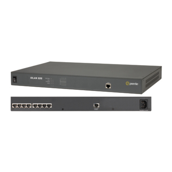
Page 37: Rack Mount
Getting to Know Your IOLAN Rack Mount This section describes the basic components of all rack mount IOLAN models. This example uses the IOLAN SCS with dual Ethernet and dual AC power. Console Port/LED View Server LEDs Serial Activity Console Port Power ON/OFF Serial/Ethernet View Serial Ports... -
Page 38: Console/Serial Switch
Console/Admin port to view diagnostic information and/or configure the IOLAN using the Menu or Command Line Interface (CLI). You can configure the baud rate and flow control of the dedicated Console port. IOLAN SDS/SCS/STS User’s Guide, Version 3.5... -
Page 39: Powering Up The Iolan
Powering Up the IOLAN Powering Up the IOLAN Desktop/Rack Mount Models To power up the IOLAN, perform the following steps: Rack Mount Models only: Using the rack mount brackets included with your IOLAN, you can rack mount the IOLAN from the front or the back of the chassis, depending on your environment. -
Page 40: Dc Power Models
Switch On the IOLAN. (The power LEDS 1 and 2 will indicate the status of the power source at the respective input. If both the primary and secondary power source are available, both LED 1 and LED 2 will be luminated indicated power detected from each input.) IOLAN SDS/SCS/STS User’s Guide, Version 3.5... -
Page 41: Disconnecting 48V Power Supplies From The Iolan
Powering Up the IOLAN Disconnecting 48V Power Supplies from the IOLAN To disconnect the power supply(s) from the IOLAN, do the following: Switch off the IOLAN. Switch off the power source(s). Disconnect all DC power input cables from the IOLAN terminal connector block. Remove any attached devices to the serial or Ethernet port(s). - Page 42 Powering Up the IOLAN IOLAN SDS/SCS/STS User’s Guide, Version 3.5...
-
Page 43: Chapter 3 Configuration Methods
Configure IOLAN server parameters. Configure serial port parameters. Configure network parameters. Configure time parameters. Reboot the IOLAN. Manage the Perle Remote Power Switch (when applicable). Manage I/O channels (when applicable). View statistics while connected to the IOLAN. IOLAN SDS/SCS/STS User’s Guide, Version 3.5... -
Page 44: Configuration Methods Overview
IOLAN+ Interface—The IOLAN+ interface is available on IOLAN models that are 1-16 ports (this is not supported on DS1 and TS2 models) and uses the interface that is available on the IOLAN+ product line. IOLAN SDS/SCS/STS User’s Guide, Version 3.5... -
Page 45: Easy Config Wizard
Printer (not supported on DS1/TS2 models) Serial Tunneling You can launch the Easy Config Wizard from the Perle website or from the installation CD-ROM. The Easy Config Wizard has been designed to walk you through the configuration process for any of the available configuration options shown on the Welcome window. -
Page 46: Devicemanager
Connecting to the IOLAN Using DeviceManager Before you can use DeviceManager, you need to install it on your Windows operating system from the IOLAN CD-ROM or you can download it from the Perle website. After the DeviceManager application is installed, click... - Page 47 DeviceManager All discovered IOLANs will be displayed on the list along with their name and IP address. When a new IOLAN is discovered on the network, that has not yet been assigned an IP address, it will be displayed with an IP Address of Not Configured. To configure the IP address, click on the IOLAN and then click the Assign IP button.
-
Page 48: Using Devicemanager
Settings Advanced When you have completed all your configuration changes, click the Download Changes button to download the configuration to the IOLAN. You must reboot the IOLAN to make those configuration changes take effect. IOLAN SDS/SCS/STS User’s Guide, Version 3.5... -
Page 49: Webmanager
From WebManager, you can launch EasyPort Web, which can be used to: access clustered IOLANs access ports configured with the Console Server profile and launch an SSH or Telnet session to those console ports exercise power management capability (when using the Perle Remote Power Switch) Configuration Methods 49... -
Page 50: Connecting To The Iolan Using Webmanager
SSL Passphrase is already defined in the IOLAN configuration and the SSL/TLS certificate/private key and CA list must have already be downloaded to the IOLAN; see Keys and Certificates on page 229 more information. IOLAN SDS/SCS/STS User’s Guide, Version 3.5... -
Page 51: Using Webmanager
WebManager Using WebManager After you have successfully logged into WebManager, you will see the following: Navigation Tree System Information You navigate through the different configuration windows by selecting an option in the left-hand navigation tree. If click on option that is next to a folder, more navigation are displayed when you click on it: Navigation Tabs folder contains two configuration options,... -
Page 52: Command Line Interface
If the login is successful, you will get a prompt that displays the IOLAN model and number of ports: Login: admin Password: SDS2# You will see a prompt that displays the model and number of the IOLAN. You are now ready to start configuring/managing your IOLAN using the CLI. IOLAN SDS/SCS/STS User’s Guide, Version 3.5... -
Page 53: Through The Serial Port
Menu Through the Serial Port To connect to the IOLAN through the serial port to configure/manage it using the CLI (or Menu), see Using a Direct Serial Connection to Specify an IP Address on page After you have established a connection to the IOLAN, you will get a Login: prompt. -
Page 54: Using The Menu
(lowercase L) to get a list of options, use the Space Bar up/down arrows to highlight the option you want, and then press to select it. Enter IOLAN SDS/SCS/STS User’s Guide, Version 3.5... -
Page 55: Dhcp/Bootp
DHCP/BOOTP DHCP/BOOTP Overview Several IOLAN parameters can be configured through a DHCP/BOOTP server during the IOLAN bootup. This is particularly useful for configuring multiple IOLANs. Not all configuration parameters are supported in the DHCP/BOOTP configuration (see DHCP/BOOTP Parameters on page 56 for supported configuration parameters), so you will need to use another configuration method, such as DeviceManager, WebManager or CLI, to complete the configuration. -
Page 56: Dhcp/Bootp Parameters
For example, 192.101.34.211 /accounting/Iolan_ds_german.txt. EXTRA_TERM1—(EXTRA_TERM2, EXTRA_TERM3) The full path, pre-fixed by a hostname/IP address (IPv4 or IPv6), and file name of a termcap file for a specific terminal type. IOLAN SDS/SCS/STS User’s Guide, Version 3.5... -
Page 57: Snmp
To connect to the IOLAN through an SNMP Management tool or MIB browser, do the following: Load the file from the IOLAN CD-ROM or Perle website into your SNMP perle-sds.MIB manager (this MIB works for all SDS, SCS, and STS models). -
Page 58: Using The Snmp Mib
If you want to save all the changes that have been submitted to the IOLAN, you need to expand the container folder and to write to FLASH. To make the adminInfo adminFunction configuration changes take effect, adminFunction to reboot the IOLAN. IOLAN SDS/SCS/STS User’s Guide, Version 3.5... -
Page 59: Iolan+ Interface
For environments that have both IOLAN and IOLAN+ models or for users who prefer to configure using the IOLAN+ Menu or CLI, the IOLAN+ user interface is available. The IOLAN+ interface is supported on all IOLAN SDS, SCS, and STS models up to and including 16 serial ports. Access Platforms The Menu is accessed by any application that supports a Telnet or SSH session to the IOLAN’s... -
Page 60: Changes To The Iolan+ Interface
User, Name—only when using LPD/LPR, Name no longer is used as the queue name Options, Rlogin/Telnet Options, Debug options Options, Hex data Options, Secure Keys, Sess Access, UDP Retries Access, Retry Interval Access, Authentication IOLAN SDS/SCS/STS User’s Guide, Version 3.5... - Page 61 IOLAN+ Interface When you select line Access , the following fields are not available on the Access Menu: ** Administrator ** ACCESS MENU REMOTE-ADMIN TTY Name Access Authentication Mode UDP Retries Interval [abcd ] [Local ] N/A [Raw [abcdef ] [Local ] N/A [Raw ________________________________________________________________________________...
- Page 62 PPP Configuration Dialer Configuration Restart timer [3 ] Dial Timeout [45] Max Retries [10] Dial Retries [2 ] Inactivity ________________________________________________________________________________ IP Address, Src Address IP Address, Dst Address Modem, Dial Comm Modem, Hang Up IOLAN SDS/SCS/STS User’s Guide, Version 3.5...
- Page 63 IOLAN+ Interface When you select server , the following fields are not available on the Server Configuration menu: ** Administrator ** SERVER CONFIGURATION REMOTE-ADMIN Name [wchiewsds2 Debug mode IP address [172.16.22.7 Subnet mask [255.255.0.0 Ethernet address (00:80:d4:88:88:88) Ethernet speed [AUTO Language [English Identification...
- Page 64 IOLAN+ Interface IOLAN SDS/SCS/STS User’s Guide, Version 3.5...
-
Page 65: Chapter 4 Getting Started
The Easy Config Wizard quickly sets up the IOLAN’s network configuration and all serial ports to one of the following: Console Management—Allows users on the network to connect to a serial device that is connected to a serial port on the IOLAN. IOLAN SDS/SCS/STS User’s Guide, Version 3.5... -
Page 66: Setting Up The Network
Setting Up the Network TruePort (Virtual COM Port)—Allows a networked system to communicate with your serial device through a virtual COM or TTY port, using the Perle TruePort software. TCP Sockets (Raw TCP)—Allows hosts on the network to communicate with a serial device that requires raw data throughput (such as a printer or card reader) connected to the IOLAN serial port. -
Page 67: Using Webmanager
Setting Up the Network Expand the Server Configuration folder and select Server . Verify the IP address configuration. You should also enter a name in the field to make the IOLAN easily identifiable. Server Name To make your edits take effect, you need to download the new configuration file and then reboot the IOLAN. -
Page 68: Using A Direct Serial Connection To Enable Bootp/Dhcp
IOLAN on the console port and reboot it or push the Reset to Factory button to access the IOLAN. You are now ready to configure the IOLAN. See Chapter 3, Configuration Methods on page 43 information on the different IOLAN configuration methods. IOLAN SDS/SCS/STS User’s Guide, Version 3.5... -
Page 69: Using Arp-Ping
Setting Up the Network Using ARP-Ping You can use the ARP-Ping (Address Resolution Protocol) method to temporarily assign an IP address and connect to your IOLAN to assign a permanent IP address. To use ARP-Ping to temporarily assign an IP address: From a local UNIX/Linux host, type the following at the system command shell prompt: arp -s a.b.c.d aa:bb:cc:dd:ee:ff ®... -
Page 70: Setting Up The Serial Port(S)
IOLAN. Both IOLAN serial ports must be configured for Serial Tunneling (typically one serial port is configured as a Tunnel Server and the other serial port as a Tunnel Client). IOLAN SDS/SCS/STS User’s Guide, Version 3.5... - Page 71 Setting Up the Serial Port(s) Virtual Modem—The Virtual Modem (Vmodem) profile configures a serial port to simulate a modem. When the serial device connected to the IOLAN initiates a modem connection, the IOLAN starts up a TCP connection to another IOLAN configured with a Virtual Modem serial port or to a host running a TCP application.
-
Page 72: Setting Up Users
To quickly add a user, fill out the field in the General tab and click Chapter 8, Configuring Users on page 189 for more information about the other user parameters you can configure. IOLAN SDS/SCS/STS User’s Guide, Version 3.5... -
Page 73: Chapter 5 Using Devicemanager And Webmanager
In DeviceManager, you must download your configuration changes to the IOLAN either periodically or after you are done with the configuration changes. From both managers you must reboot the IOLAN in order for you configuration changes to take effect. IOLAN SDS/SCS/STS User’s Guide, Version 3.5... -
Page 74: Navigating Devicemanager/Webmanager
The DeviceManager uses a folder/page navigation tree. You can expand the folders to see the available configuration pages. When you access a configuration page, you can often navigate the tabs in the configuration area to access all of the configuration options. Menu/Quick Access Buttons Navigation Tree Configuration Area IOLAN SDS/SCS/STS User’s Guide, Version 3.5... -
Page 75: Webmanager
Navigating DeviceManager/WebManager WebManager The WebManager uses a expandable/collapsible buttons with folders and pages for the navigation tree. You can expand the buttons to view the folders and pages to see the available configuration options. When you access a configuration page, you can often navigate the tabs in the configuration area to access all of the configuration options. -
Page 76: Using Devicemanager To Connect To The Iolan
IOLAN’s IP address; this field supports IPv4 and IPv6 addresses. Click the button when you have completed adding all the manual entries. Select Close the manually added server to connect to it. IOLAN SDS/SCS/STS User’s Guide, Version 3.5... -
Page 77: Assigning A Temporary Ip Address To A New Iolan
Using DeviceManager to Connect to the IOLAN Assigning a Temporary IP Address to a New IOLAN You can temporarily assign an IP address to the IOLAN that is connected to your local network segment, for the purpose of connecting to it and downloading a configuration file (containing a permanent IP address). -
Page 78: Adding/Deleting Manual Iolans
DeviceManager can communicate with the IOLAN’s IP Address. If the ping times out, then you might need to set up a Gateway in your IOLAN or verify that your network is communicating correctly. IOLAN SDS/SCS/STS User’s Guide, Version 3.5... -
Page 79: Using Webmanager To Connect To The Iolan
A user who does not Login have admin privileges can access EasyPort Web to access clustered serial ports, Perle Remote Power Switches (RPS), and/or RPS plugs (must already be configured on this IOLAN) by typing their user name and password on the login screen. -
Page 80: Opening An Existing Configuration File
Most of the management tasks, such as setting the time/date, downloading keys/certificates, downloading firmware, downloading custom files, resetting serial ports, etc., are found under the menu option in the DeviceManager and under in WebManager. Tools Administration IOLAN SDS/SCS/STS User’s Guide, Version 3.5... -
Page 81: Chapter 6 Network Settings
Advanced—This window configures hosts that the IOLAN will be communicating with, routes, DNS/WINS servers, RIP, Dynamic DNS, and IPv6 Tunnels. See Advanced on page 89 for more information on these options. IOLAN SDS/SCS/STS User’s Guide, Version 3.5... -
Page 82: Ip Settings
Use the following Assign a specific IP address to the IOLAN. IP Address IP Address The IOLAN’s unique IPv4 network IP address. Field Format: IPv4 address Subnet Mask The network subnet mask. For example, 255.255.0.0. IOLAN SDS/SCS/STS User’s Guide, Version 3.5... - Page 83 IP Settings Default Gateway Specify the gateway IP address that will provide general access beyond the local network. Field Format: IPv4 address Default Gateway When DHCP/BOOTP is enabled, you can enable this option to have the Obtain IOLAN receive the Default Gateway IP address from the DHCP/BOOTP Automatically server.
-
Page 84: Ipv6 Settings
Edits an existing IPv6 address. Delete Button Deletes an IPv6 address from the Custom IPv6 address list. Default Gateway Specify the gateway IP address that will provide general access beyond the local network. Field Format: IPv6 address IOLAN SDS/SCS/STS User’s Guide, Version 3.5... -
Page 85: Adding/Editing A Custom Ipv6 Address
IP Settings DSN Server Specify the IPv6 address of a DNS host in your network for host name resolution. Field Format: IPv6 address DNS Server Obtain When DHCPv6 is enabled, you can enable this option to have the IOLAN Automatically receive the DNS IP address from the DHCPv6 server. -
Page 86: Advanced
DNS will be one of the following formats, depending on what is configured in the System Settings section on the tab: IPv4 Settings <Server Name>.<Domain Prefix>.<Domain Name> <Server Name>.<Domain Prefix> Field Format: Maximum 8 alphanumeric characters IOLAN SDS/SCS/STS User’s Guide, Version 3.5... - Page 87 IP Settings Enable Active (SCS models only) permits the grouping of Ethernet LAN Active Standby Standby connections to provide for link failover. Both Ethernet connections will have the same Ethernet MAC address. Active standby refers to the process by which a failure of one interface can be automatically overcome by having its traffic routed to the other interface.
- Page 88 Data Options: and Duplex Auto —automatically detects the Ethernet interface speed and duplex 10 Mbps Half Duplex 10 Mbps Full Duplex 100 Mbps Half Duplex 100 Mbps Full Duplex 1000 Mbps Full Duplex Default: Auto IOLAN SDS/SCS/STS User’s Guide, Version 3.5...
-
Page 89: Advanced
Advanced Advanced Host Table Overview The Host table contains the list of hosts that will be accessed by an IP address or Fully Qualified Domain Name (FQDN) from the IOLAN. This table will contain a symbolic name for the host as well as its IP address or FQDN. -
Page 90: Adding/Editing A Host
Fully Qualified When you have DNS defined in the IOLAN, you can enter a DNS resolvable Domain Name fully qualified domain name (note: FQDN’s are excluded as accessible hosts when is enabled). IP Filtering IOLAN SDS/SCS/STS User’s Guide, Version 3.5... -
Page 91: Route List
Advanced Route List Overview Entering routes in the routing list enables the identification of gateways to be used for accessing specific hosts or external networks from the IOLAN's local network. Functionality There are three types of routes: Default—A route that provides general access beyond your local network. Host—A route defined for accessing a specific host external to your local network. -
Page 92: Adding/Editing Routes
IPv6 Prefix Bits If the IP address is IPv6, then you must specify the network’s prefix bits. Range: 0-128 Host Select this option when a host is being used at the route gateway. Default: Enabled, None IOLAN SDS/SCS/STS User’s Guide, Version 3.5... -
Page 93: Dns/Wins
Advanced Interface The Interface list is comprised of configured IPv6 tunnels and serial ports defined for Remote Access (PPP) and Remote Access (SLIP) profiles. Select this option when you want to use the specified interface as the gateway to the destination. -
Page 94: Editing/Adding Dns/Wins Servers
Listen—Routing information is only received from the remote user. Send and Listen—Routing information is transmitted to and received from the remote user. The local parameter or RADIUS parameter, if set, override the serial User Routing Framed-Routing port parameter for a connection. Routing IOLAN SDS/SCS/STS User’s Guide, Version 3.5... -
Page 95: Field Descriptions
Advanced Field Descriptions Configure the appropriate parameters: Ethernet Mode Enable/disable RIP (Routing Information Protocol) mode for the Ethernet interface. Data Options: None—Disables RIP over the Ethernet interface. Send—Sends RIP over the Ethernet interface. Listen—Listens for RIP over the Ethernet interface. Send and Listen—Sends RIP and listens for RIP over the Ethernet interface. -
Page 96: Dynamic Dns
IOLAN will automatically update its IP address with DynDNS.org if it changes. Default: Disabled Host Specify the registered hostname with DynDNS.org that will be updated with the IOLAN’s IP address should it change. Put in the full name; for example, mydeviceserver.dyndns.org IOLAN SDS/SCS/STS User’s Guide, Version 3.5... -
Page 97: Account Settings
Advanced User Name Specify the user name used to access the account set up on the DynDNS.org server. Password Specify the password used to access the account set up on the DynDNS.org server. Account Settings Click this button to configure the Dynamic DNS DynDNS.org account Button information. -
Page 98: Cipher Suite Field Descriptions
Delete Button Deletes a cipher to the cipher list. Move Up Button Moves a cipher up in preference in the cipher list. Move Down Button Moves a cipher down in preference in the cipher list. IOLAN SDS/SCS/STS User’s Guide, Version 3.5... -
Page 99: Adding/Editing A Cipher Suite
Advanced Adding/Editing a Cipher Suite To see a list of valid cipher suite combinations, see Appendix B, SSL/TLS Ciphers on page 337. Configure the following parameters: Encryption Select the type of encryption that will be used for the SSL connection. Data Options: Any—Will use the first encryption format that can be negotiated. -
Page 100: Validation Criteria Field Descriptions
Organization Unit An entry for the unit in the organization; for example, Payroll. This field is case sensitive in order to successfully match the information in the peer SSL/TLS certificate. Data Options: Maximum 64 characters IOLAN SDS/SCS/STS User’s Guide, Version 3.5... -
Page 101: Ipv6 Tunnels
Advanced Common Name An entry for common name; for example, the host name or fully qualified domain name. This field is case sensitive in order to successfully match the information in the peer SSL/TLS certificate. Data Options: Maximum 64 characters Email An entry for an email address;... -
Page 102: Adding/Editing An Ipv6 Tunnel
The interface that the IOLAN is going to use to access the Remote Host. The list is comprised of the Ethernet interface(s) and serial ports configured for the Remote Access (PPP) or Remote Access (SLIP) profiles. Default: Ethernet 1 IOLAN SDS/SCS/STS User’s Guide, Version 3.5... -
Page 103: Chapter 7 Configuring Serial Ports
Serial Ports on your IOLAN. As you configure the serial ports, the information for each serial port is displayed. To configure/change a serial port, click the Edit button. IOLAN SDS/SCS/STS User’s Guide, Version 3.5... -
Page 104: Editing A Serial Port
Serial Ports Editing a Serial Port In the Serial Port Settings window, click on a serial port and then click the button, the Edit following window is displayed: IOLAN SDS/SCS/STS User’s Guide, Version 3.5... -
Page 105: Copying A Serial Port
Serial Ports Click the Change Profile button to select a different serial port profile if you don’t want the displayed profile: As you select the different serial port profiles, a short description and a picture representing a typical application of the profile is displayed. When you have selected the appropriate profile for the serial port, click and those serial port profile configuration options will be displayed. -
Page 106: Resetting A Serial Port
Email Alert Tab Field Descriptions on page 109. System Packet Forwarding—Configure data packet parameters. See Packet Forwarding Tab Field Descriptions on page 110. SSL/TLS—Configure SSL/TLS encryption options for the serial port. See SSL/TLS Setting Tab Field Descriptions on page 113. IOLAN SDS/SCS/STS User’s Guide, Version 3.5... -
Page 107: Hardware Tab Field Descriptions
Serial Port Profiles Hardware Tab Field Descriptions tab configures all the serial port hardware connection information. The window below Hardware shows an SDS1 model; your Hardware tab might display a subset of the parameters described, depending on the IOLAN model and supported hardware. Configure the following parameters: Serial Interface Specifies the type of serial line that is being used with the IOLAN. - Page 108 If your application cannot handle loopback data, echo suppression should be enabled. Default: Disabled IOLAN SDS/SCS/STS User’s Guide, Version 3.5...
-
Page 109: Email Alert Tab Field Descriptions
Serial Port Profiles Email Alert Tab Field Descriptions Email notification can be set at the Server and/or serial port levels. You can set unique email notifications for each serial port because the person who administers the IOLAN might not be the same person who administers the serial device(s) attached to the IOLAN port. -
Page 110: Packet Forwarding Tab Field Descriptions
IOLAN. Range: 0-65535 Default: 250 ms Custom Packet This option allows you to define the packet forwarding rules based on the Forwarding packet definition or the frame definition. Default: Disabled IOLAN SDS/SCS/STS User’s Guide, Version 3.5... - Page 111 Serial Port Profiles Packet Definition When enabled, this group of parameters allows you to set a variety of packet definition options. The first criteria that is met causes the packet to be transmitted. For example, if you set a ms and a Force Transmit Timer 1000 bytes, whichever criteria is met first is what will cause the...
- Page 112 Trigger1/Trigger2, depending on your settings, plus the first byte that follows the trigger. Trigger+2—Includes the EOF1, EOF1/EOF2, Trigger1, or Trigger1/Trigger2, depending on your settings, plus the next two bytes received after the trigger. Default: Trigger IOLAN SDS/SCS/STS User’s Guide, Version 3.5...
-
Page 113: Ssl/Tls Setting Tab Field Descriptions
Serial Port Profiles SSL/TLS Setting Tab Field Descriptions You can create an encrypted connection using SSL/TLS for any serial port profile that accesses the IOLAN from the network. When you enable this feature, it will automatically use the global SSL/TLS settings (configured on Security SSL/TLS ), although you can configure unique SSL/TLS... -
Page 114: Cipher Suite Field Descriptions
Delete Button Deletes a cipher to the cipher list. Move Up Button Moves a cipher up in preference in the cipher list. Move Down Button Moves a cipher down in preference in the cipher list. IOLAN SDS/SCS/STS User’s Guide, Version 3.5... -
Page 115: Adding/Editing A Cipher Suite
Serial Port Profiles Adding/Editing a Cipher Suite To see a list of valid cipher suite combinations, see Appendix B, SSL/TLS Ciphers on page 337. Configure the following parameters: Encryption Select the type of encryption that will be used for the SSL connection. Data Options: Any—Will use the first encryption format that can be negotiated. -
Page 116: Validation Criteria Field Descriptions
Organization Unit An entry for the unit in the organization; for example, Payroll. This field is case sensitive in order to successfully match the information in the peer SSL/TLS certificate. Data Options: Maximum 64 characters IOLAN SDS/SCS/STS User’s Guide, Version 3.5... -
Page 117: Console Management Profile
Serial Port Profiles Common Name An entry for common name; for example, the host name or fully qualified domain name. This field is case sensitive in order to successfully match the information in the peer SSL/TLS certificate. Data Options: Maximum 64 characters Email An entry for an email address;... -
Page 118: Advanced Tab Field Descriptions
Default: Disabled Enable Message of Enables/disables the display of the message of the day. the Day (MOTD) Default: Disabled IOLAN SDS/SCS/STS User’s Guide, Version 3.5... - Page 119 Serial Port Profiles Multisessions The number of extra network connections available on a serial port, in addition to the single session that is always available. Enabling multisessions will permit multiple users to monitor the same console port. Each user monitoring the port can be assigned different privileges to this port.
-
Page 120: Trueport Profile
Although the port will still operate as a COM port, control signals are ignored. In this mode, the serial communications parameters must be configured on the IOLAN. See the TruePort User’s Guide for more details about the TruePort client software. IOLAN SDS/SCS/STS User’s Guide, Version 3.5... -
Page 121: General Tab Field Descriptions
Serial Port Profiles General Tab Field Descriptions tab determines how the TruePort connection is initiated and then sets up the TruePort General appropriate connection parameters. Configure the following parameters: Connect to remote When enabled, the IOLAN initiates communication to the TruePort client. system Default: Enabled Host Name... -
Page 122: Adding/Editing Additional Trueport Hosts
Once connected to the backup, the IOLAN will attempt to re-establish a connection to the Primary host, once this is successfully done, it gracefully shuts down the backup connection. Default: Disabled IOLAN SDS/SCS/STS User’s Guide, Version 3.5... -
Page 123: Adding/Editing A Multihost Entry
Serial Port Profiles Primary Host Specify a preconfigured host that the serial device will communicate to through the IOLAN. Default: None TCP Port Specify the TCP port that the IOLAN will use to communicate to the Primary Host Default: 0 Backup Host Specify a preconfigured host that the serial device will communicate to through the IOLAN if the IOLAN cannot communicate with the... -
Page 124: Advanced Tab Field Descriptions
"testing" the connection. It should be noted that if a network connection is accidentally dropped, it can take as long as the specified interval before anyone can reconnect to the serial port. Default: Disabled IOLAN SDS/SCS/STS User’s Guide, Version 3.5... - Page 125 Serial Port Profiles Enable Data When enabled, serial data will be buffered if the TCP connection is lost. When Logging the TCP connection is re-established, the buffered serial data will be sent to its destination (this option is not available when , or Monitor DSR Monitor DCD...
-
Page 126: Tcp Sockets Profile
Workstation/Server or the IOLAN. General Tab Field Descriptions Configure the following parameters: Listen for When enabled, the IOLAN listens for a connection to be established by the Connection Workstation/Server on the network. Default: Enabled IOLAN SDS/SCS/STS User’s Guide, Version 3.5... - Page 127 Serial Port Profiles TCP Port The TCP port that the IOLAN will use to listen for incoming connections. Default: 10000 plus the serial port number, so serial port 5 would have a default of 10005 Allow Multiple When this option is enabled, multiple hosts can connect to the serial device that Hosts to Connect is connected to this serial port.
-
Page 128: Adding/Editing Additional Hosts
IOLAN will attempt to re-establish a connection to the Primary host, once this is successfully done, it gracefully shuts down the backup connection. Default: Disabled Primary Host Specify a preconfigured host that the serial device will communicate to through the IOLAN. Default: None IOLAN SDS/SCS/STS User’s Guide, Version 3.5... -
Page 129: Adding/Editing A Multihost Entry
Serial Port Profiles TCP Port Specify the TCP port that the IOLAN will use to communicate to the Primary Host Default: 0 Backup Host Specify a preconfigured host that the serial device will communicate to through the IOLAN if the IOLAN cannot communicate with the Primary Host Default: None TCP Port... -
Page 130: Advanced Tab Field Descriptions
Use this timer to close a connection because of inactivity. When the Idle expires, the IOLAN will end the connection. Timeout Range: 0-4294967 seconds (about 49 days) Default: seconds so the port will never timeout IOLAN SDS/SCS/STS User’s Guide, Version 3.5... - Page 131 Serial Port Profiles Session Timeout Use this timer to forcibly close the session/connection when the Session expires. Timeout Default: seconds so the port will never timeout Range: 0-4294967 seconds (about 49 days) Dial In If the device is remote and will be dialing in via modem or ISDN TA, enable this parameter.
-
Page 132: Udp Sockets Profile
All UDP data received from hosts that have an IP address that falls within the range of will be sent to the serial device. The IOLAN Port 33010 172.16.1.20 172.16.1.50 will not send any data received on its serial port. IOLAN SDS/SCS/STS User’s Guide, Version 3.5... -
Page 133: General Tab Field Descriptions
Serial Port Profiles UDP Entry 3 All hosts that have an IP Address that falls within the range of 172.16.1.75 172.16.1.80 and who listen to Port 33009 will receive UDP data from the serial device. The IOLAN will listen for messages on the port value configured in the Listen for connections on UDP port parameter. -
Page 134: Terminal Profile
This profile can be configured for users: who must be authenticated by the IOLAN first and then a connection to a host can be established. who are connecting through the serial port directly to a host. IOLAN SDS/SCS/STS User’s Guide, Version 3.5... -
Page 135: General Tab Field Descriptions
Serial Port Profiles General Tab Field Descriptions Configure the following parameters: Terminal Type Specifies the type of terminal connected to the line. Data Options: Dumb WYSE60 VT100 ANSI TVI925 IBM3151TE VT320 (specifically supporting VT320-7) HP700 (specifically supporting HP700/44) Term1, Term2, Term3 (user-defined terminals) Default: Dumb Require Login When users access the IOLAN through the serial port, they must be... - Page 136 Initiates a connection to the specified host when any data is received on the received serial port. Default: Disabled When <hex value> Initiates a connection to the specified host only when the specified character is is received received on the serial port. Default: Disabled IOLAN SDS/SCS/STS User’s Guide, Version 3.5...
-
Page 137: Advanced Tab Field Descriptions
Serial Port Profiles Advanced Tab Field Descriptions Configure the following parameters: Enable Message of Enables/disables the display of the message of the day. the Day (MOTD) Default: Disabled Reset Terminal on When enabled, resets the terminal definition connected to the serial port when disconnect a user logs out. - Page 138 If the device is remote and will be dialing in via modem or ISDN TA, enable this parameter. Default: Disabled Dial Out If you want the modem to dial a number when the serial port is started, enable this parameter. Default: Disabled IOLAN SDS/SCS/STS User’s Guide, Version 3.5...
-
Page 139: User Service Settings
Serial Port Profiles User Service Settings Login Settings These settings apply to users who are accessing the network from a terminal connected to the IOLAN’s serial port. The Telnet, Rlogin, SSH, SLIP, PPP settings take effect when the connection method is defined in the user’s profile (or are passed to the IOLAN by a RADIUS or TACACS+ server when those authentication methods are being used). -
Page 140: Telnet Settings
Echo Defines the echo character. When , typing the echo character Line Mode echoes the text locally and sends only completed lines to the host. This value is in hexadecimal. Default: 5 (ASCII value IOLAN SDS/SCS/STS User’s Guide, Version 3.5... -
Page 141: Rlogin Settings
Serial Port Profiles Escape Defines the escape character. Returns you to the command line mode. This value is in hexadecimal. Default: 1d (ASCII value Rlogin Settings The Rlogin settings apply when the is set to or the Terminal profile has User Service Rlogin Require... -
Page 142: Ssh Settings
When enabled, selects an SSH version 2 connection. If both SSH 1 and SSH 2 are selected, the IOLAN will attempt to make an SSH 2 connection first. If that connection fails, it will attempt to connect to the specified host using SSH 1. Default: Enabled IOLAN SDS/SCS/STS User’s Guide, Version 3.5... -
Page 143: Slip Settings
Serial Port Profiles SSH2 Ciphers Select the order of negotiation for the encryption method (ciphers) that the Opt1-5 IOLAN will use for the SSH version 2 connection: Data Options: 3DES Blowfish Arcfour CAST When enabled, an authentication method used by SSH version 1 and 2. Use RSA authentication for the SSH session. - Page 144 RADIUS and the RADIUS parameter Framed-Compression is set in the RADIUS file, the IOLAN will use the value in the RADIUS file in preference to the value configured here. Default: Enabled IOLAN SDS/SCS/STS User’s Guide, Version 3.5...
-
Page 145: Ppp Settings
Serial Port Profiles PPP Settings The PPP settings apply when the is set to User Service Configure the following parameters: IPv4 Local IP The IPV4 IP address of the IOLAN end of the PPP link. For routing to work, Address you must enter a local IP address. - Page 146 (password). A timer operates during which successful authentication must take place. If the timer expires before the remote end has been authenticated successfully, the link will be terminated. Default: CHAP IOLAN SDS/SCS/STS User’s Guide, Version 3.5...
- Page 147 Serial Port Profiles User Complete this field only if you have specified (security CHAP protocols) in the field, and Authentication you wish to dedicate this line to a single remote user, who will be authenticated by the IOLAN, or you are using the IOLAN as a router (back-to-back with another IOLAN). When Connect is set to...
- Page 148 Range: 0-255 Default: 2 seconds Configure NAK The maximum number of times a packet will be re-sent configure NAK Retries before the link is terminated. Range: 0-255 Default: 10 seconds IOLAN SDS/SCS/STS User’s Guide, Version 3.5...
- Page 149 Serial Port Profiles Authentication The timeout, in minutes, during which successful PAP or CHAP authentication Timeout must take place (when are specified). If the timer expires before CHAP the remote end has been authenticated successfully, the link will be terminated. Range: 1-255 Default: 1 minute Roaming Callback A user can enter a telephone number that the IOLAN will use to callback...
-
Page 150: Printer Profile
The Printer profile allows for the serial port to be configured to support a serial printer device that can be access by the network. General Tab Field Descriptions Configure the following parameter: Map CR to CR/LF Defines the default end-of-line terminator as CR/LF (ASCII carriage-return line-feed) when enabled. Default: Disabled IOLAN SDS/SCS/STS User’s Guide, Version 3.5... -
Page 151: Serial Tunneling Profile
Serial Port Profiles Serial Tunneling Profile Overview The Serial Tunneling profile allows two IOLANs to be connected back-to-back over the network to establish a virtual link between two serial ports based on RFC 2217. Functionality The serial device that initiates the connection is the Tunnel Client and the destination is the Tunnel... -
Page 152: General Tab Field Descriptions
A preconfigured host name that is associated with the IP address of the Tunnel Server. TCP Port The TCP port that the IOLAN will use to connect to the Tunnel Server. Default: 10000+serial port number; so serial port 5 is 10005. IOLAN SDS/SCS/STS User’s Guide, Version 3.5... -
Page 153: Virtual Modem Profile
Serial Port Profiles Virtual Modem Profile Overview Virtual Modem (Vmodem) is a feature of the IOLAN that provides a modem interface to a serial device. It will respond to AT commands and provide signals in the same way that a serially attached modem would. -
Page 154: General Tab Field Descriptions
Default: Enabled Verbose String When enabled, the connection status is sent by text strings to the connected device. Default: Disabled IOLAN SDS/SCS/STS User’s Guide, Version 3.5... -
Page 155: Advanced Tab Field Descriptions
Serial Port Profiles Success String String that is sent to the serial device when a connection succeeds. Default: CONNECT <speed>, for example, CONNECT 9600 Failure String String that is sent to the serial device when a connection fails. Default: NO CARRIER Numeric Codes When enabled, the connection status is sent to the connected device using the following numeric codes:... - Page 156 Default: Disabled AT Command The amount of time, in milliseconds, before an AT response is sent to the Response Delay requesting device. Default: 250 ms IOLAN SDS/SCS/STS User’s Guide, Version 3.5...
-
Page 157: Phone Number To Host Mapping
Serial Port Profiles Phone Number to Host Mapping If your modem application dials using a phone number, you can add an entry in the Phone Number to Host Mapping window that can be accessed by all serial ports configured as Virtual Modem. You need to enter the phone number sent by your modem application and the IOLAN IP address and TCP Port that will be receiving the ’call.’... -
Page 158: Vmodem Phone Number Entry
Digital Input (DSR, DCD, and CTS) or Digital Output (DTR and RTS). Functionality The Control Signal I/O profile enables the use of the EIA-232 serial port pins to be used as assigned Digital Inputs or Digital Outputs. IOLAN SDS/SCS/STS User’s Guide, Version 3.5... -
Page 159: General Tab Field Descriptions
Serial Port Profiles General Tab Field Descriptions tab displays the signal pins. This window is also used to enable/disable the signal pins. General Highlight a signal and then click the button to configure the signal pin’s parameters. Edit Input Signal Field Descriptions Configure the following parameters: Description Provide a description of the channel, making it easier to identify. - Page 160 Critical Default: Disabled SNMP When enabled, sends an SNMP trap when an alarm is triggered or cleared. The trap consists of the severity level and whether the alarm was triggered or cleared. Default: Disabled IOLAN SDS/SCS/STS User’s Guide, Version 3.5...
-
Page 161: Output Signal Field Descriptions
Serial Port Profiles Output Signal Field Descriptions Configure the following parameters: Description Provide a description of the channel, making it easier to identify. Data Options: Maximum 20 characters, including spaces Failsafe Action When there has been no I/O activity within the specified time (set in the I/O Interfaces, Settings on the Failsafe Timer tab) and the Failsafe Timer triggered. -
Page 162: Modbus Gateway Profile
Access on page 259 for more information on using the Modbus protocol to access I/O data. Functionality The Modbus Gateway profile configures a serial port to act as a Modbus Master Gateway or a Modbus Slave Gateway. IOLAN SDS/SCS/STS User’s Guide, Version 3.5... -
Page 163: General Tab Field Descriptions
Serial Port Profiles General Tab Field Descriptions Configure the following parameters: Mode Specify how the Modbus Gateway is defined on the serial port. Data Options: Modbus Master—Typically, the Modbus Master is connected to the Serial Port and is communicating to Modbus Slaves on the network. Modbus Slave—Typically, the Modbus Master is accessing the IOLAN through the network to communicated to Modbus Slaves connected to the IOLAN’s Serial Ports. -
Page 164: Advanced Field Descriptions
Time to wait, in milliseconds, for a response message from a Modbus TCP or serial slave (depending if the Modbus Gateway is a Master Gateway or Slave Gateway, respectively) before sending a Modbus exception. Range: 10-10000 Default: 1000 ms IOLAN SDS/SCS/STS User’s Guide, Version 3.5... -
Page 165: Modbus Slave Ip Settings Field Descriptions
Serial Port Profiles Modbus Slave IP Settings Field Descriptions This window is used to configure the Modbus Slaves. The following buttons are available: Add Button Adds an entry into the Modbus Destination Slave IP Settings table. Edit Button Edits an entry in the Modbus Destination Slave IP Settings table. Delete Button Deletes an entry from the Modbus Destination Slave IP Settings table. -
Page 166: Adding/Editing Modbus Slave Ip Settings
Gateway—The Modbus Master Gateway will use the same IP address when connecting to all the remote Modbus slaves in the specified UID range. Default: Host Start IP Address The IP address of the TCP/Ethernet Modbus Slave. Field Format: IPv4 or IPv6 address IOLAN SDS/SCS/STS User’s Guide, Version 3.5... -
Page 167: Modbus Slave Advanced Settings Field Descriptions
Serial Port Profiles End IP Address Displays the ending IP address of the TCP/Ethernet Modbus Slaves, based on the Start IP address and the UID range (not supported for IPv6 addresses). Field Format: IPv4 address Protocol Specify the protocol that is used between the Modbus Master and Modbus Slave(s). -
Page 168: Power Management Profile
Default: Disabled Power Management Profile Overview The Power Management profile applies when there is a Perle Remote Power Switch (RPS) connected to the serial port. This profile is used to configure the RPS. See RPS Control on page 293 information on how to actively management the RPS. -
Page 169: General Tab Field Descriptions
Serial Port Profiles General Tab Field Descriptions Configure the following parameters: RPS Name Specify a name for the RPS. RPS Model Specify the RPS model. Data Options: RSP820, RPS830, RPS1620, RPS1630 Default: RSP820 Edit Button Highlight a plug and then click the Edit button to configure the plug. -
Page 170: Remote Access (Ppp) Profile
Remote Password fields blank. An example of the CHAP secrets file follows: # Secrets for authentication using CHAP # client server secret acceptable local IP addresses barney fred flintstone1234567890 192.168.43.1 fred barney wilma 192.168.43.2 IOLAN SDS/SCS/STS User’s Guide, Version 3.5... -
Page 171: General Tab Field Descriptions
Serial Port Profiles An example of the PAP secret file follows: # Secrets for authentication using PAP # client server secret acceptable local IP addresses barney flintstone1234567890 fred wilma General Tab Field Descriptions Configure the following parameters: IPv4 Local IP The IPV4 IP address of the IOLAN end of the PPP link. - Page 172 You can optionally specify an IPv6 global network prefix that the IOLAN will Network Prefix advertise to the device at the other end of the PPP link. Default: 0:0:0:0 IPv6 Prefix Bits Specify the prefix bits for the IPv6 global network prefix. Default: 64 IOLAN SDS/SCS/STS User’s Guide, Version 3.5...
-
Page 173: Authentication Tab Field Descriptions
Serial Port Profiles Authentication Tab Field Descriptions Configure the following parameters: Authentication The type of authentication that will be done on the link. You can use to authenticate a serial port or user on the IOLAN, from a remote CHAP location, or authenticate a remote client/device, from the IOLAN. - Page 174 The timeout, in minutes, during which successful PAP or CHAP authentication Timeout must take place (when are specified). If the timer expires before CHAP the remote end has been authenticated successfully, the link will be terminated. Range: 1-255 Default: 1 minute IOLAN SDS/SCS/STS User’s Guide, Version 3.5...
-
Page 175: Dynamic Dns Field Descriptions
Serial Port Profiles CHAP Challenge The interval, in minutes, for which the IOLAN will issue a CHAP re-challenge Interval to the remote end. During CHAP authentication, an initial CHAP challenge takes place, and is unrelated to CHAP re-challenges. The initial challenge takes place even if re-challenges are disabled. -
Page 176: Advanced Tab Field Descriptions
If your user is authenticated by RADIUS and the RADIUS parameter is set in the RADIUS file, the IOLAN will use the value in the Framed-MTU RADIUS file in preference to the value configured here. Range: 64-1500 bytes Default: 1500 IOLAN SDS/SCS/STS User’s Guide, Version 3.5... - Page 177 Serial Port Profiles Configure Request The maximum time, in seconds, that LCP (Link Control Protocol) will wait Timeout before it considers a packet to have been lost. configure request Range: 1-255 Default: 3 seconds Configure Request The maximum number of times a packet will be re-sent configure request Retries...
-
Page 178: Remote Access (Slip) Profile
SLIP Remote Access (SLIP) connection to the IOLAN’s serial port. This is typically used with a modem for dial-in or dial-out access to the network. IOLAN SDS/SCS/STS User’s Guide, Version 3.5... -
Page 179: General Tab Field Descriptions
Serial Port Profiles General Tab Field Descriptions Configure the following parameters: Local IP Address The IPv4 address of the IOLAN end of the SLIP link. For routing to work you must enter an IP address in this field. Choose an address that is part of the same network or subnetwork as the remote end;... -
Page 180: Advanced Tab Field Descriptions
RADIUS file in preference to the value configured here. Default: Enabled Direct Connect If the device is remote and will be dialing in via modem or ISDN TA, enable this parameter. Default: Disabled IOLAN SDS/SCS/STS User’s Guide, Version 3.5... -
Page 181: Custom Application Profile
Custom App/Plugin IOLAN by using the Perle SDK. See the SDK Programmer’s Guide (the SDK and guide are found on the Perle website at ) for information about the www.perle.com/downloads/index.shtml... -
Page 182: General Tab Field Description
To return to communicating to the device, press the key and the communication session will continue from where you left off. IOLAN SDS/SCS/STS User’s Guide, Version 3.5... -
Page 183: Remote Port Buffers
NFS server to convert the encrypted data to a readable file for administrators to analyze. The Decoder Utility can be found on your installation CDROM or on the Perle website (www.perle.com). The data that is sent to the remote buffer file is appended to the end of the file (even through IOLAN reboots), so you will want to create a size limit on the file on your remote NFS host, to keep the buffer file size from becoming too large for your system. -
Page 184: Field Definitions
NFS host for decrypting the data to a readable format. The Decoder utility software can be found on the installation CD-ROM and on the website. www.perle.com Default: Disabled IOLAN SDS/SCS/STS User’s Guide, Version 3.5... -
Page 185: Advanced
Advanced Duplicate NFS to When enabled, buffered data is sent to the syslog host to be viewed on the Syslog host’s monitor. Default: Disabled Add Time Stamp to Enable/disable time stamping of the serial port buffer data. Data Default: Disabled Enable Key Stroke When enabled, key strokes that are sent from the network host to the serial Buffering... - Page 186 < > (for example, ESC-b <027>b Default: <016> (Ctrl-p) Monitor Specify how often, in seconds, the IOLAN will send a TCP Keepalive to Connection services that support TCP Keepalive. Interval Status Default: 30 seconds IOLAN SDS/SCS/STS User’s Guide, Version 3.5...
-
Page 187: Modems Tab
Advanced Modems Tab Overview You need to configure a modem if there is a modem connected to the IOLAN. If your IOLAN model contains an internal modem or a PCI slot (SCS models) for a modem card, a permanent modem string called internal_modem IOLAN modem... -
Page 188: Trueport Baud Rate Tab
Field Definitions Configure the following parameter: Actual Baud Rate The actual baud rate that runs between the IOLAN and the connected serial device. Range: 50-230400, you can also specify a custom baud rate IOLAN SDS/SCS/STS User’s Guide, Version 3.5... -
Page 189: Chapter 8 Configuring Users
Provide authentication on the IOLAN prior to establishing a serial connection via PPP or SLIP. Authenticate users prior to providing access to a serially attached console port (such as a Unix server or router). Note: You do not need user accounts for users who are externally authenticated. IOLAN SDS/SCS/STS User’s Guide, Version 3.5... -
Page 190: User Settings
The Users window displays the users who have been configured. You can add users, edit existing users, or delete users from this window. See Adding/Editing Users on page 191 for information on the parameters available when adding or editing a user. IOLAN SDS/SCS/STS User’s Guide, Version 3.5... -
Page 191: Adding/Editing Users
Adding/Editing Users Adding/Editing Users General Tab Overview The General tab configures the basic user information. Functionality You must, minimally, provide a User Name Level for a user. Field Descriptions Configure the following parameters: User Name The name of the user. Restrictions: Do not use spaces. - Page 192 Host IP address 127.0.0.0 (local loop back). When the user connects to that serial port a Telnet session will be established to the IOLAN and the user will appear to have connected from the network. IOLAN SDS/SCS/STS User’s Guide, Version 3.5...
-
Page 193: Services Tab
Adding/Editing Users Services Tab Overview tab configures the connection parameters for a user. Any connection parameters Services configured in this window will override the serial port connection parameters. Functionality When a Terminal profile is set for the serial port and Require Login has been selected, user’s accessing the IOLAN through the serial port will be authenticated. - Page 194 None—RIP packets are neither received nor sent by the IOLAN. Send—RIP packets can only be sent by the IOLAN. Listen—RIP packets can only be received by the IOLAN. Send and Listen—RIP packets are sent and received by the IOLAN. Default: None IOLAN SDS/SCS/STS User’s Guide, Version 3.5...
-
Page 195: Advanced Tab
Adding/Editing Users Enable VJ Used for , determines whether Van Jacobsen User Service PPP SLIP Compression Compression is used on the link. VJ compression is a means of reducing the standard TCP/IP header from 40 octets to approximately 5 octets. This gives a significant performance improvement, particularly when interactive applications are being used. - Page 196 Serial Port Hotkey Prefix value. You can use the Hotkey Prefix keys to lock a serial port only when the serial port’s Allow Port Locking parameter is enabled. Default: Hex 01 (Ctrl-a or ^a) IOLAN SDS/SCS/STS User’s Guide, Version 3.5...
-
Page 197: Sessions Tab
Adding/Editing Users Sessions Tab Overview tab is used to configure specific connections for users who are accessing the network Sessions through the IOLAN’s serial port. Functionality Users who have successfully logged into the IOLAN ( User Service set to DSprompt ) can start up to four login sessions on network hosts. -
Page 198: Field Descriptions
The host that the user will connect to in this predefined session. Default: None TCP Port The TCP port that the IOLAN will use to connect to the host in this predefined session. Default: Telnet-23, SSH-22, Rlogin-513 IOLAN SDS/SCS/STS User’s Guide, Version 3.5... -
Page 199: Serial Port Access Tab
Adding/Editing Users Serial Port Access Tab Overview tab controls the user’s read/write access on any given IOLAN serial port. Serial Port Access This pertains to users that are connecting from the network to a serial over a Console Management type session. This can be useful when you have multiple users connecting to the same serial device and you wish to control the viewing and/or the write to and from the device. - Page 200 Adding/Editing Users IOLAN SDS/SCS/STS User’s Guide, Version 3.5...
-
Page 201: Chapter 9 Configuring Security
For example, user Alfred’s user ID is maintained in the secondary authentication database, therefore, he will be prompted for his password twice, because he is not in the primary authentication database. IOLAN SDS/SCS/STS User’s Guide, Version 3.5... -
Page 202: Authentication
When disabled, a user called admin must exist when only external authentication methods are configured, or you will not be able to access the IOLAN as the admin user, except through the console port. Default: Enabled IOLAN SDS/SCS/STS User’s Guide, Version 3.5... -
Page 203: Local
Authentication Local Overview When authentication is selected, the user must either be configured in the IOLAN’s Local User List or you must enable users. Guest Field Descriptions Configure the following parameters: Enable Guest Mode Allow users who are not defined in the database to log into the IOLAN Users with any user ID and the specified password. -
Page 204: Radius
Name of the primary RADIUS accounting host. Host Default: None Second Accounting Name of the secondary RADIUS accounting host. Host Default: None Secret The secret (password) shared between the IOLAN and the RADIUS accounting host. IOLAN SDS/SCS/STS User’s Guide, Version 3.5... -
Page 205: Kerberos
Authentication Account Port The port that the RADIUS host listens to for accounting requests. Default: 1813 Enable Accounting Enables/disables whether or not the IOLAN validates the RADIUS accounting Authenticator response. Default: Enabled Retry The number of times the IOLAN tries to connect to the RADIUS server before erroring out. -
Page 206: Ldap
The domain component (dc) that is the starting point for the search for user authentication. Enable TLS Enables/disables the Transport Layer Security (TLS) with the LDAP host. Default: Disabled TLS Port Specify the port number that LDAP will use for Default: 636 IOLAN SDS/SCS/STS User’s Guide, Version 3.5... -
Page 207: Tacacs
Authentication TACACS+ Overview TACACS+ is an authentication method that the IOLAN supports that can send back User information; see Appendix , TACACS+ on page 332 for more information on the parameters User that can be sent back by TACACS+. Field Descriptions Configure the following parameters: Authentication/ The primary TACACS+ host that is used for authentication. -
Page 208: Securid
Default: SDI Legacy If you are running SecurID 3.x or 4.x, you need to run in . If you Legacy Mode are running SecurID 5.x or above, do not select Legacy Mode Default: Disabled IOLAN SDS/SCS/STS User’s Guide, Version 3.5... -
Page 209: Nis
Authentication Field Descriptions Configure the following parameters: NIS Domain The NIS domain name. Primary NIS Host The primary NIS host that is used for authentication. Default: None Secondary NIS Host The secondary NIS host that is used for authentication, should the primary NIS host fail to respond. -
Page 210: Ssh
Lynn Private Key Tracy Network Device Server Public Key Tracy Private Key Device Server Device Server Private Key Dennis Server Lynn Public Key Device Server Public Key Tracy Public Key Dennis Private Key Dennis Public Key IOLAN SDS/SCS/STS User’s Guide, Version 3.5... -
Page 211: Users Passing Through The Iolan Using Ssh (Dir/Sil)
Users Passing Through the IOLAN Using SSH (Dir/Sil) This scenario applies to serial ports configured for the profile and are required to login to Terminal the IOLAN. The user’s service is set to the SSH protocol, therefore, users first log into the IOLAN and then are connected to a specified host (configured for the user when User Service SSH selected) through an SSH connection. -
Page 212: Field Descriptions
Default: Enabled Blowfish The IOLAN SSH server’s Blowfish encryption is enabled/disabled. Default: Enabled Arcfour The IOLAN SSH server’s Arcfour encryption is enabled/disabled. Default: Enabled The IOLAN SSH server’s AES encryption is enabled/disabled. Default: Enabled IOLAN SDS/SCS/STS User’s Guide, Version 3.5... -
Page 213: Ssl/Tls
SSL/TLS Break String The break string used for inband SSH break signal processing. A break signal is generated on a specific serial port only when the server's break option is enabled and the user currently connected using reverse SSH has typed the break string exactly. -
Page 214: Field Descriptions
HTTP option (HTTPS) or SSL/TLS. If both RSA and DSA private keys are downloaded to the IOLAN, they need to be generated using the same SSL passphrase for both to work. IOLAN SDS/SCS/STS User’s Guide, Version 3.5... -
Page 215: Cipher Suite Field Descriptions
SSL/TLS Cipher Suite Field Descriptions The SSL/TLS cipher suite is used to encrypt data between the IOLAN and the client. You can specify up to five cipher groups. The following buttons are available on the Cipher Suite window: Add Button Adds a cipher to the cipher list. -
Page 216: Adding/Editing A Cipher
ADH—This is an anonymous key exchange which does not require a private key or certificate. Choose this key if you do not want to authenticate the peer device, but you want the data encrypted on the SSL/TLS connection. Default: Any IOLAN SDS/SCS/STS User’s Guide, Version 3.5... -
Page 217: Validation Criteria Field Descriptions
SSL/TLS HMAC Select the key-hashing for message authentication method for your encryption type. Data Options: SHA1 Default: Any Validation Criteria Field Descriptions If you choose to configure validation criteria, then the information in the peer SSL/TLS certificate must match exactly the information configured in this window in order to pass peer authentication and create a valid SSL/TLS connection. -
Page 218: Vpn
REQUIRED to be set to the following values to support a VPN tunnel between the IOLAN and a VPN server/client: perfect forward secrecy: no protocol: ESP mode: tunnel (not transport) opportunistic encryption: no aggressive mode: no IOLAN SDS/SCS/STS User’s Guide, Version 3.5... -
Page 219: Ike Phase 1 Proposals
IKE Phase 1 Proposals The following IKE Phase 1 proposals are supported by the IOLAN VPN gateway: Ciphers—3DES, AES Hashes—MD5, SHA1 Diffie-Hellman Groups—2 (MODP1024), 5 (MODP1536), 14 (MODP2048), 15 (MODP3072), 16 (MODP4096), 17 (MODP6144), 18 (MODP8192) ESP Phase 2 Proposals The following ESP Phase 2 proposals are supported by the IOLAN VPN gateway: Ciphers—3DES, AES Authentication Algorithms—MD5, SHA1, SHA2... -
Page 220: Adding/Editing The Ipsec Tunnel
X.509 Certificate—X.509 certificates are used to authenticate the IPsec tunnel. When using this authentication method, you must include the signing authority’s certificate information in the SSL/TLS CA list and download it to the IOLAN. Default: Shared Secret IOLAN SDS/SCS/STS User’s Guide, Version 3.5... - Page 221 Secret/Remote Depending on the Authentication Method Validation Criteria Shared Secret—Specify the text-based secret that is used to authenticate the Button IPsec tunnel (case sensitive). This applies to all VPN tunnels (IPsec and L2TP/IPsec). X.509 Certificate—Specify the remote X.509 certificate validation criteria that must match for successful authentication (case sensitive).
-
Page 222: Shared Secret Field Description
Configure the following parameter: Secret When the is set to , enter the Authentication Method Shared Secret case-sensitive secret word.This applies to all VPN tunnels (IPsec and L2TP/IPsec). Text Characteristics: Maximum of 16 characters, spaces not allowed IOLAN SDS/SCS/STS User’s Guide, Version 3.5... -
Page 223: Remote Validation Criteria Field Descriptions
Remote Validation Criteria Field Descriptions When the is set to , you can configure the remote Authentication Method X.509 Certificate validation criteria. The information in the remote X.509 certificate must match exactly the information configured in this window in order to successfully authenticate and create a valid connection. -
Page 224: L2Tp/Ipsec
X.509 Certificate—X.509 certificates are used to authenticate the IPsec tunnel. When using this authentication method, you must include the signing authority’s certificate information in the SSL/TLS CA list and download it to the IOLAN. Default: Shared Secret IOLAN SDS/SCS/STS User’s Guide, Version 3.5... -
Page 225: Exceptions
Remote Validation Depending on the Authentication Method Criteria Shared Secret—Specify the text-based secret that is used to authenticate the IPsec tunnel (case sensitive). This applies to all VPN tunnels (IPsec and L2TP/IPsec). X.509 Certificate—Specify the remote X.509 certificate validation criteria that must match for successful authentication (case sensitive). -
Page 226: Adding/Editing A Vpn Exception
Field Description Configure the following parameter: Use NAT Traversal NAT Traversal should be enabled when the IOLAN is communicating through (NAT_T) a router/gateway to a remote VPN that also has NAT Traversal enabled. Default: Enabled IOLAN SDS/SCS/STS User’s Guide, Version 3.5... -
Page 227: Services
Services Services Overview Services are either daemon or client processes that run on the IOLAN. You can disable any of the services for security reasons. Functionality If you disable any of the daemons, it can affect how the IOLAN can be used or accessed. For example, if you disable WebManager (HTTPS and HTTP) services, you will not be able to access the IOLAN with the WebManager. - Page 228 Default: Enabled Dynamic Routing Dynamic Routing daemon process in the IOLAN listening on port 520. (RIP) Default: Enabled IPsec IPsec daemon process in the IOLAN listening and sending on UDP port 500. Default: Disabled IOLAN SDS/SCS/STS User’s Guide, Version 3.5...
-
Page 229: Keys And Certificates
Keys and Certificates Keys and Certificates When you are using SSH, SSL/TLS, LDAP, or HTTPS, you will need to install keys and/or certificates or get server keys in order to make those options work properly. All certificates need to be created and all keys need to be generated outside of the IOLAN, with the exception of the IOLAN SSH Public keys, which already exist in the IOLAN. - Page 230 The name of the host for which you are downloading the SSH Host Public Private Key to the IOLAN. IPsec Tunnel Name Select the IPsec tunnel that the RSA public key is being used to authenticate. IOLAN SDS/SCS/STS User’s Guide, Version 3.5...
-
Page 231: Chapter 10 Configuring I/O Interfaces
Temperature Input Some of the models are I/O combinations and some of the models support one I/O type, although all of the I/O models are extensions of the feature rich, extended temperature SDS IOLAN. IOLAN SDS/SCS/STS User’s Guide, Version 3.5... -
Page 232: Settings
TruePort COM redirector feature. TruePort Default: Disabled Modbus I/O Access on page 259 for function codes and I/O coil/registration descriptions and Accessing I/O Data Via TruePort on page for the Perle API. IOLAN SDS/SCS/STS User’s Guide, Version 3.5... -
Page 233: Advanced Slave Modbus Settings
Allow I/O Access Allows serial application access to the I/O over the network using the TruePort via API through COM redirector feature via a custom application using the Perle API. TruePort Default: Permanently enabled when Enable I/O Access via TruePort... - Page 234 Specify the UID that will be inserted into the message header for the Slave Modbus serial device. Range: 1-247 Default: 1 Enable SSL/TLS When enabled, Modbus Slave Gateway messages to remote TCP Modbus using global settings Masters are encrypted via SSL/TLS. Default: Disabled IOLAN SDS/SCS/STS User’s Guide, Version 3.5...
-
Page 235: Failsafe Timer Functionality
Settings Failsafe Timer Functionality Overview tab configures the I/O failsafe timer. The Failsafe Timer is enabled on a global Failsafe Timer basis and provides a trigger mechanism that can be configured for each channel when no I/O traffic/management has occurred for the specified amount of time. A Failsafe Action can be configured for each Digital Output channel, each Serial Signal Output channel (DTR and RTS), and each Relay channel to either Activate or Deactivate the output. -
Page 236: Udp Functionality
Default: 30 seconds Settings Button Click this button to configure the UDP IP addresses that will receive the I/O status information. I/O UDP Settings on page 237 for field descriptions for the I/O UDP Settings window. IOLAN SDS/SCS/STS User’s Guide, Version 3.5... -
Page 237: I/O Udp Settings
Settings I/O UDP Settings Configure the following parameters: UDP Entry When enabled, broadcasts I/O status (data) to the specified range of IP addresses. Default: Disabled Start IP Address The first host IP address in the range of IP addresses (for IPV4 or IPV6) that the IOLAN will listen for messages from and/or send messages to. -
Page 238: Temperature Functionality
T4 models. Temperature Field Descriptions Configure the following parameter: Temperature Scale Select the temperature scale that will be used to display temperature data. Data Options: Fahrenheit or Celsius Default: Celsius IOLAN SDS/SCS/STS User’s Guide, Version 3.5... -
Page 239: Channels
(monitored by an Analog channel) a syslog message is sent to the Monitoring Application. The Monitoring Application then sends a command to the IOLAN via the Perle API that causes the Relay channel to activate an internal freezer dehumidifier. The relay is turned off when the Analog channel sends a clear syslog message to the Monitoring Application and the Relay channel is deactivated. -
Page 240: Field Descriptions
Alarm Settings Button alarms. Notice that the Analog Alarm Settings window has two alarm configuration views, a basic alarm view and an advanced alarm view. Alarm Settings on page 252 for field descriptions. IOLAN SDS/SCS/STS User’s Guide, Version 3.5... -
Page 241: Digital Input
Channels Digital Input Overview When the channel is set for digital input, it monitors voltage or current. Note that the internal jumpers must match the software setting and must be set to Input, which is the default; see Digital I/O Module on page 356 to find out how to set the internal jumpers. -
Page 242: Field Descriptions
Disabled—No alarm settings. This is the default. Inactive—When the expected Digital input is active, going inactive will trigger an alarm. Active—When the expected Digital input is inactive, going active will trigger an alarm. Default: Disabled IOLAN SDS/SCS/STS User’s Guide, Version 3.5... - Page 243 Channels Auto Clear Mode When enabled, automatically clears the alarm when the trigger condition changes; for example, if the and the alarm is triggered, once Trigger Inactive the input becomes active again, the alarm will automatically be cleared Default: Enabled Manual Clear When enabled, a triggered alarm must be manually cleared.
-
Page 244: Digital Output
In an industrial freezer warehouse, the IOLAN D4 is used to monitor the freezer doors. When one of the industrial freezer doors are left open for more than five minutes, the Monitoring Application (using the Perle API) starts the Digital output sink, causing the strobe light on top of the offending freezer to activate. -
Page 245: Field Descriptions
Channels Field Descriptions Configure the following parameters: Description Provide a description of the channel, making it easier to identify. Data Options: Maximum 20 characters, including spaces Output Mode When selected, the channel will drive the line (output). The internal jumpers must match the software configuration, so if you change this setting to Output , you will have to also change the internal hardware jumpers. - Page 246 Interfaces, Settings on the Failsafe Timer tab) and the Failsafe Timer triggered. Data Options: None—The state of the Digital/Relay output remains the same, no change. Activate Output—Activates the channel. Deactivate Output—Deactivates the channel. Default: None IOLAN SDS/SCS/STS User’s Guide, Version 3.5...
-
Page 247: Relay
Channels Relay Overview Relay channels can open or close a contact for a higher voltage circuit using a lower level control voltage. The Relay output channels work as a physical on/off switch, and are used to drive higher voltage devices with a lower controlling voltage. You can configure the following Relay output channel options: You can choose to manually activate/deactivate the Relay output. -
Page 248: Field Descriptions
The channel output will pulse for the specified number of times; each count consists of an active/inactive sequence. Default: 1 Inactive Signal How long the channel will remain inactive during pulse mode. Width Range: 1-9999 x 100 ms Default: 1 (100 ms) IOLAN SDS/SCS/STS User’s Guide, Version 3.5... - Page 249 Channels Active Signal How long the channel will be active during the pulse mode. Width Range: 1-9999 x 100 ms Default: 1 (100 ms) Delay How long to delay an active-to-inactive or inactive-to-active setting after it is manually started. Range: 1-9999 x 100 ms Default: 1 (100 ms) Failsafe Action When there has been no I/O activity within the specified time (set in the I/O...
-
Page 250: Temperature
In the following example, a Temperature I/O IOLAN is used to monitor industrial freezer temperature sensors, with an alarm set to send a syslog message if the temperature rises above 31 Network Temperature I/O Device Server Monitoring Application Industrial Freezers IOLAN SDS/SCS/STS User’s Guide, Version 3.5... -
Page 251: Field Descriptions
Channels Field Descriptions Configure the following parameters: Description Provide a description of the channel, making it easier to identify. Data Options: Maximum 20 characters, including spaces Type Specify the type of sensor you are using to measure temperature. Data Options: RTD, Thermocouple Default: RTD Range Specify the temperature range that you want to measure. -
Page 252: Alarm Settings
The email alert data includes the severity level and the value that caused the alarm to trigger or clear. The Email Alert is associated with Level Critical Default: Disabled IOLAN SDS/SCS/STS User’s Guide, Version 3.5... -
Page 253: Advanced Analog Alarm Settings
Channels Send Syslog Alert When enabled, sends a message to syslog when an alarm is triggered or cleared. The syslog entry includes the severity level and the value that caused the alarm to trigger or clear. The syslog message is associated with Level Critical Default: Disabled... - Page 254 Critical Default: Disabled SNMP When enabled, sends an SNMP trap when an alarm is triggered or cleared. The trap consists of the severity level and whether the alarm was triggered or cleared. Default: Disabled IOLAN SDS/SCS/STS User’s Guide, Version 3.5...
-
Page 255: I/O Udp
I/O UDP I/O UDP Industrial applications often monitor the status of I/O devices such as sensors, alarms, relays, etc. by polling for I/O data. The IOLAN’s I/O UDP feature can help to minimize network traffic by broadcasting I/O status to industrial applications on specified intervals, providing I/O status in a timely manner. -
Page 256: Analog Section
Analog or Celsius/Fahrenheit for Temperature until it is cleared. maxEngValue—The maximum raw value that has been converted to voltage/current for Analog or Celsius/Fahrenheit for Temperature until it is cleared. IOLAN SDS/SCS/STS User’s Guide, Version 3.5... -
Page 257: Digital/Relay Section
I/O UDP Digital/Relay Section The Digital/Relay Section of the UDP packet provides the status of Digital and Relay channels. The data for the status of each channel is represented by 1 byte, with each bit representing a channel (least significant bit format). Note: The Digital/Relay Channel Data subsection is present in the UDP packet regardless of whether or not the IOLAN model supports Digital/Relay channels. -
Page 258: Udp Unicast Example
Modbus serial application as described in TruePort I/O on page 264 and connect to the IOLAN over the network. UID: 15 Power Network Device Server PC running a Modbus Serial I/O Digital Application Output IOLAN SDS/SCS/STS User’s Guide, Version 3.5... -
Page 259: Modbus Tcp Application
Modbus I/O Access Modbus TCP Application If you have a Modbus RTU or Modbus ASCII program, you can access the I/O by connecting to the IOLAN over the network. UID: 15 Power Network Device Server PC running a Modbus RTU I/O Digital or ASCII Output... -
Page 260: I/O Coil/Register Descriptions
IOLAN was re-started or a manual clear was issued. MB_REG_IR_ALARM_LEVEL—This gives the current alarm severity level for the corresponding Analog input. Severity levels range from 0 (not in alarm) to 5 (highest alarm severity). IOLAN SDS/SCS/STS User’s Guide, Version 3.5... -
Page 261: Serial Port Coil/Register Descriptions
Modbus I/O Access Serial Port Coil/Register Descriptions This section contains descriptions of serial port coils: MB_REG_DI_DSR—The status of the DSR input signal. 1 is Active, 0 is Inactive. If Invert is configured , 0 is Active, 1 is Inactive. If input is , returns latched status. -
Page 262: A4D2/A4R2 Registers
----- MB_REG_IR_MIN_RAW 2087 2119 2151 2183 ----- ----- MB_REG_IR_MAX_RAW 2088 2120 2152 2184 ----- ----- MB_REG_IR_ALARM_LEVEL 2089 2121 2153 2185 ----- ----- *For DI alarm state, read will get state, write will clear alarm. IOLAN SDS/SCS/STS User’s Guide, Version 3.5... -
Page 263: D4/D2R2 Registers
Modbus I/O Access D4/D2R2 Registers The following coils and registers are supported by the IOLAN D4 and D2R2 I/O models: Data Model D3/R1 D4/R2 Coils: MB_REG_DI_SENSOR 6145 6146 6147 6148 MB_REG_DI_SENSOR_ALARM_STATE 6209 6210 6211 6212 MB_REG_DO_SENSOR 6657 6658 6659 6660 Holding Registers: MB_REG_HR_DI_SENSOR_LATCH 6145... -
Page 264: Trueport I/O
IOLAN and the host machine (SSL/TLS must be configured in the Server settings and on the TruePort host). UID: 15 Power Network PC running a IOLAN Modbus Serial Application/ I/O Digital TruePort Output The host running TruePort must be in Modbus/ASCII or Modbus/RTU mode. IOLAN SDS/SCS/STS User’s Guide, Version 3.5... -
Page 265: Api Over Trueport Only
If you have a custom application that talks to a serial port, you can use TruePort as a virtual serial port to communicate with the IOLAN over the network to access I/O data using the Perle API. You also have the option of enabling SSL as a security option to encrypt the data that is communicated between the IOLAN and the host machine (SSL/TLS must be configured in the Server settings and on the TruePort host). -
Page 266: Accessing I/O Data Via Trueport
TruePort where they will be made available to be read from the COM port. Once the desired operations are completed, the COM port can be closed. IOLAN SDS/SCS/STS User’s Guide, Version 3.5... -
Page 267: Format Of Api Commands
Accessing I/O Data Via TruePort Format of API Commands There are two groups of commands: Get Commands—Retrieve values of the I/O channel registers Set Commands—Set values on the I/O channel registers. Note: All commands need to be written to the COM port as a single write. I/O Channel registers are all assigned unique addresses, which need to be referenced in all of the commands. -
Page 268: Set Commands
If accessing registers which are 2 or 4 bytes, the data is in Network order (Big endian) format (that is, MSB, LSB). For Boolean registers, the value field will be a bit field with the LSBit corresponding to the IO channel referenced by the starting register. IOLAN SDS/SCS/STS User’s Guide, Version 3.5... -
Page 269: Successful Response Format
Accessing I/O Data Via TruePort Successful Response Format Byte(s) # of Bytes Value Command code (from request). Starting register number (see A4/T4 Registers on page 261, A4D2/A4R2 Registers on page 262, or D4/D2R2 Registers on page 263 for this value) from request. Number of registers written. -
Page 270: Error Codes
Trap for the Analog input Alarm Level 2 Clear. IO_AI_ALARM_LEVEL3_CLEAR Trap for the Analog input Alarm Level 3 Clear. IO_AI_ALARM_LEVEL4_CLEAR Trap for the Analog input Alarm Level 4 Clear. IO_AI_ALARM_LEVEL5_CLEAR Trap for the Analog input Alarm Level 5 Clear. IOLAN SDS/SCS/STS User’s Guide, Version 3.5... -
Page 271: Chapter 11 Configuring Clustering
Select a Slave IOLAN and click this button to delete it from the clustering group. Advanced Button Select a Slave IOLAN and click this button to configure the individual Slave IOLAN’s serial ports. Advanced Clustering Slave Options on page 273 for more information. IOLAN SDS/SCS/STS User’s Guide, Version 3.5... -
Page 272: Adding Clustering Slaves
IOLAN. Default: 1024, and then increments by one for each new slave entry Protocol Specify the protocol that will be used to access the slave IOLAN port. Data Options: SSH, Telnet Field Format: Telnet IOLAN SDS/SCS/STS User’s Guide, Version 3.5... -
Page 273: Advanced Clustering Slave Options
Clustering Slave List Advanced Clustering Slave Options Overview button provides a means of configuring each individual serial port’s name, connection Advanced protocol, and port association in the clustered IOLAN slave. The Clustering Slave Settings window displays each clustered serial port slave entry, you need to click the Edit button to configure the individual serial port settings. - Page 274 User’s will use this TCP port number to access the Slave IOLAN’s port. Default: 1024, and then increments by one for each new slave entry Protocol Specify the protocol that will be used to access the port. Data Options: SSH, Telnet Default: Telnet IOLAN SDS/SCS/STS User’s Guide, Version 3.5...
-
Page 275: Chapter 12 Configuring The Option Card
Perle IOLAN Option Card modem card or a Perle PCI Adapter/wireless WAN card. Functionality The Perle IOLAN modem card or Perle PCI Adapter/wireless WAN card slide into the PCI slot as described in Installing a Perle PCI Card on page 369. -
Page 276: Configuring A Wireless Wan Card
Sony Ericsson—You are using a Sony Ericsson wireless WAN card. Use Standard Driver—If the wireless WAN card you are using is not listed, try the standard driver. Use Custom Driver—A custom driver downloaded from the Perle website. Default: Sierra Wireless AirCard 881... - Page 277 Configuring a Wireless WAN Card Specify the APN required by your internet provider to access their network. See the internet provider documentation for more information. User Name Specify the name required by your internet provider to access their network. Password Specify the password required by your internet provider to access their network.
- Page 278 Configuring a Wireless WAN Card IOLAN SDS/SCS/STS User’s Guide, Version 3.5...
-
Page 279: Chapter 13 Configuring The System
The following events trigger an email notification on the System for the specified Level Reboot, Alert Level IOLAN System Failure, Error Level Authentication Failure, Notice Level Successful Login, Downloads (all), Configuration Save Commands, Info Level IOLAN SDS/SCS/STS User’s Guide, Version 3.5... -
Page 280: Field Descriptions
Outgoing Mail The SMTP host (email server) that will process the email notification request. Server This can be either a host name defined in the IOLAN host table or the SMTP host IP address. IOLAN SDS/SCS/STS User’s Guide, Version 3.5... -
Page 281: Syslog
Alerts Syslog Overview The IOLAN can be configured to send system log messages to a syslog daemon running on a remote host if the service is activated. You can configure a primary and secondary host for the syslog Syslog information and specify the level for which you want syslog information sent. Note: You must ensure that the service in the... -
Page 282: Management
IOLAN; this can be done in the DeviceManager, WebManager, CLI, or Menu. You must then load the perle-sds.MIB (found on the CD-ROM packaged with the IOLAN) file into your SNMP manager before you connect to the IOLAN. - Page 283 Management Internet Address The IP address of the SNMP manager that will send requests to the IOLAN. If the address is , any SNMP manager with the name can Community 0.0.0.0 access the IOLAN. If you specify a network address, for example , any SNMP manager within the local network with the 172.16.0.0 name can access the IOLAN.
-
Page 284: Time
PC’s time. Therefore, if you set the IOLAN’s time to 2:30 pm in the DeviceManager, the IOLAN’s actual internal clock time is 5:30 pm. This is the only configuration method that interprets the time and converts it between time zones, as necessary. IOLAN SDS/SCS/STS User’s Guide, Version 3.5... -
Page 285: Network Time Tab Field Descriptions
Management Network Time Tab Field Descriptions You can configure your SNTP client in the IOLAN to automatically synchronize the IOLAN’s time. Configure the following parameters: SNTP Mode The SNTP mode. Data Options: None—SNTP is turned off. Unicast—Sends a request packet periodically to the Primary host. If communication with the Primary host fails, the request will be sent to the Secondary host. -
Page 286: Time Zone/Summer Time Tab Field Descriptions
Sets the exact date and time in which the IOLAN’s clock will change to summer time (daylight saving time) hours. Fixed End Date Sets the exact date and time in which the IOLAN’s clock will end summer time hours and change to standard time. IOLAN SDS/SCS/STS User’s Guide, Version 3.5... -
Page 287: Custom App/Plugin
Custom App/Plugin Overview You can create custom applications for the IOLAN by using the Perle SDK. See the SDK Programmer’s Guide (the SDK and guide are found on the Perle website at ) for information about the functions that are www.perle.com/downloads/index.shtml... -
Page 288: Advanced
If this limit is exceeded, the serial port is disabled for 5 minutes. A user with Admin level rights can restart the serial port, bypassing the timeout, by issuing a kill on the disabled serial port. Default: 3 IOLAN SDS/SCS/STS User’s Guide, Version 3.5... -
Page 289: Bootup Files Tab Field Descriptions
Management Bootup Files Tab Field Descriptions You must have a TFTP server running on any host that you are uploading or downloading files to/from. When you specify the file path, the path must be relative to the default path set in your TFTP server software. -
Page 290: Message Of The Day (Motd) Tab Field Descriptions
TFTP fail. Range: 0-5 Default: 5 Timeout The time, in seconds, that the IOLAN will wait for a successful transmit or receipt of TFTP packets before retrying a TFTP transfer. Range: 3-10 Default: 3 seconds IOLAN SDS/SCS/STS User’s Guide, Version 3.5... -
Page 291: Console Port Tab Field Descriptions
Management Console Port Tab Field Descriptions This tab is found on rack mount models and is used to configure the Admin/Console port. Configure the following parameters: Baud Rate Specifies the baud rate of the line connected to the dedicated console port. Data Options: 9600, 19200, 38400, 57600, 115200 Default: 9600 Flow Control... - Page 292 Management IOLAN SDS/SCS/STS User’s Guide, Version 3.5...
-
Page 293: Chapter 14 Controlling The Rps, I/O Channels, And Ipsec Tunnels
Resets all the RPS plugs to the default state as configured in the Power State Button Management profile settings. Plug Control Button Displays a window that allows you to manage the individual plugs on the RPS. IOLAN SDS/SCS/STS User’s Guide, Version 3.5... -
Page 294: Plug Control
The following buttons are available: On Button Turns the selected plug on. Off Button Turns the selected plug off. Cycle Button Turns the selected plug off and then on. OK Button Closes the window. IOLAN SDS/SCS/STS User’s Guide, Version 3.5... -
Page 295: Serial Port Power Control
Serial Port Power Control Serial Port Power Control Overview window allows you to manage the power plugs that have been Serial Port Power Control associated with the serial devices connected to the IOLAN. Field Descriptions The following buttons are available: On Button Turns the selected plug on. -
Page 296: I/O Channels
Manually activates the channel output. Button Deactivate Output Manually deactivates the channel output. Button Reset All Channels Resets all the channels. Button Refresh Button Resets the highlighted channel (click on a channel to highlight it). IOLAN SDS/SCS/STS User’s Guide, Version 3.5... -
Page 297: Ipsec Tunnel Control
IPsec Tunnel Control IPsec Tunnel Control You can start, stop, and restart all the IPsec tunnels. When you start the IPsec tunnels, the Boot configured for each IPsec tunnel is what determines its state. Action The following buttons are available: Start Button Starts all IPsec VPN tunnels. - Page 298 IPsec Tunnel Control IOLAN SDS/SCS/STS User’s Guide, Version 3.5...
-
Page 299: Chapter 15 System Administration
Download All Changes button. Reboot the IOLAN. In WebManager: Under the option, select Administration Backup/Restore Browse to the configuration file that you want to download to the IOLAN. Click the button. Restore Reboot the IOLAN. IOLAN SDS/SCS/STS User’s Guide, Version 3.5... -
Page 300: Downloading Configuration Files To Multiple Iolans
IOLAN is rebooted. Click to add the IOLAN to the download list. You can also click on the IOLAN entry and edit any information and then click to make the edits permanent. Update IOLAN SDS/SCS/STS User’s Guide, Version 3.5... -
Page 301: Uploading Configuration Files
Downloading IOLAN Firmware Click the Download> button to start the download process. A status window will display with the configuration download status. Uploading Configuration Files When you upload a configuration to the DeviceManager, you are uploading the IOLAN’s working configuration file. In most other configurators (the exception being SNMP), you are always seeing the working configuration file. -
Page 302: Calibrating I/O
.15% accuracy. When you calibrate one channel, all thermocouple channels are automatically calibrated for that range; if another channel is set for a different range, you will need to calibrate that channel separately, but all channels that use that range are automatically calibrated. IOLAN SDS/SCS/STS User’s Guide, Version 3.5... -
Page 303: Calibrating Rtd
Calibrating I/O Calibrating RTD When calibrating the IOLAN Analog input for RTD, you will need a resistor that is better than .05% Ohms accuracy. When you calibrate one channel, all RTD channels are automatically calibrated for that range; if another channel is set for a different range, you will need to calibrate that channel separately, but all channels that use that range are automatically calibrated. -
Page 304: Resetting Calibration Data
When you download any file (configuration, keys, certificates, firmware, etc.) to the IOLAN, you must reboot the IOLAN for it to take effect by selecting Tools Reset Reboot Server DeviceManager and Administration Reboot Unit in WebManager. IOLAN SDS/SCS/STS User’s Guide, Version 3.5... -
Page 305: Resetting The Iolan To Factory Defaults
Resetting the IOLAN to Factory Defaults Resetting the IOLAN to Factory Defaults You can reset the IOLAN to its factory default configuration by selecting Tools Reset Reset to in DeviceManager and in WebManager. Factory Default Administration Reset Factory Defaults The IOLAN will automatically reboot itself with the factory default configuration. Resetting the SecurID Node Secret If you are using SecurID external authentication, you can select Tools... -
Page 306: Translation Guidance
Existing text strings, if altered, will be altered in sequence; that is, in their current position in the file. The existing sequence of lines will be unchanged. Until you have the changes translated, new text strings will appear in the Menu or CLI in English. IOLAN SDS/SCS/STS User’s Guide, Version 3.5... -
Page 307: Downloading Terminal Definitions
Downloading Terminal Definitions Downloading Terminal Definitions All terminal types can be used on the IOLAN. Some terminal types which are not already defined in the IOLAN, however, are unable to use Full Screen mode (menus) and may not be able to page through sessions properly. -
Page 308: Resetting Configuration Parameters
CLI, at the command line type, reset factory WebManager, select Administration Reboot Unit , and then click the Reboot button Menu, select Network Configuration Reset to Factory Defaults SNMP, in the folder, variable to adminInfo adminFunction IOLAN SDS/SCS/STS User’s Guide, Version 3.5... -
Page 309: Lost Admin Password
Lost Admin Password Lost Admin Password If the Admin user password is lost, there are only two possible ways to recover it: reset the IOLAN to the factory defaults have another user that has level rights, if one is already configured, reset the Admin admin password... - Page 310 Lost Admin Password IOLAN SDS/SCS/STS User’s Guide, Version 3.5...
-
Page 311: Chapter 16 Applications
Applications Chapter 16 Introduction This chapter provides examples of how to integrate the IOLAN within different network environments or applications. Each scenario provides an example of a typical setup and describes the configuration steps to achieve the IOLAN functionality feature. Configuring Modbus This sections provides a brief overview of the steps required to configure the IOLAN for your Modbus environment. -
Page 312: Modbus Gateway Settings
Configuring Modbus Modbus Gateway Settings The scenarios in this section are used to illustrate how the IOLAN’s Modbus Gateway settings are incorporated into a Modbus device environment. Depending on how your Modbus Master or Slave devices are distributed, the IOLAN can act as both a Slave and Master Gateway(s) on a multiport IOLAN or as either a Slave or Master Gateway on a single port IOLAN. -
Page 313: Modbus Serial Port Settings
Configuring Modbus Modbus Serial Port Settings Modbus Master Settings When the Modbus Masters is attached to the IOLAN’s serial port, configure that serial port to the profile acting as a Modbus Master. You must configure the Modbus TCP Slaves Modbus Gateway on the TCP/Ethernet side so the IOLAN can properly route messages, using the Modbus Slave’s UIDs, to the appropriate TCP-attached devices. -
Page 314: Modbus Slave Settings
Configuring Modbus Modbus Slave Settings When you have Modbus Slaves on the serial side of the IOLAN, configure the serial port to the profile acting as a Modbus Slave. There is only one Slave Gateway in the IOLAN, Modbus Gateway so all Modbus serial Slaves must be configured uniquely for that one Slave Gateway;... -
Page 315: Configuring Ppp Dial On Demand
Configuring PPP Dial On Demand Configuring PPP Dial On Demand The IOLAN can be configured to access remote networks via modems connected to the serial interface of the IOLAN. By configuring the IOLAN for the profile, data that Remote Access (PPP) is destined for the remote network will initiate a modem connection to the remote network to route the data to its appropriate destination. -
Page 316: Setting Up Printers
Setting Up Printers Next you need to create a gateway and destination route entry. Select , and Network Advanced Route List tab. For the destination, if you want the connection to be able to reach any host in the remote network, set the and specify the network IP address and subnet/prefix bits;... -
Page 317: Remote Printing Using Rcp
Setting Up Printers Remote Printing Using RCP When setting up a serial port that accesses a printer using RCP, do the following: Set the serial port to and configure the , and Printer Speed Flow Control Stop Bits Parity Bits parameters so that they match the printer’s port settings. -
Page 318: Configuring A Virtual Private Network
Configuring a Virtual Private Network Configuring a Virtual Private Network You can configure the IOLAN to act as a Virtual Private Network (VPN) gateway using the IPsec protocol. Any of the following scenarios can be configured using one IOLAN and a host/server running IPsec software or two IOLANs, each acting as the VPN gateway. - Page 319 Configuring a Virtual Private Network Use a utility (for example, Openswan’s newhostkey/showhostkey utilities) to generate the RSA signature public key. Copy the public key portion to a file using the following format: <description>=<keydata> or just <keydata> For example: # RSA 1024 bits scs48_vpn Tue Jan 3 15:29:33 2006...
-
Page 320: Network-To-Network
Configuring a Virtual Private Network Network-to-Network The following examples shows how to configure a network-to-network IPsec tunnel. This example uses the X.509 Certificate authentication method, so it includes the configuration requirements for the X.509 certificate. is enabled in this example (on both sides) because the NAT Traversal (NAT_T) VPN tunnel is going private network to public network to private network. -
Page 321: Host-To-Host
Configuring a Virtual Private Network If the signer of the remote X.509 certificate has not already been included in the CA list file that has already been downloaded to the IOLAN, you need to add (append) the signer of the X.509 certificate to the CA list file and then download the file to the IOLAN by selecting Tools Advanced... - Page 322 Configuring a Virtual Private Network The following window configures the Right IOLAN VPN Gateway: is entered for the because the IP address is DHCP assigned Local IP Address %defaultroute and is therefore subject to change. is entered for the Remote IP Address to indicate that it will accept a VPN connection %any from any host/network;...
-
Page 323: Vpn Client-To-Network
Configuring a Virtual Private Network VPN Client-to-Network The following example shows how to configure a VPN client-to-network IPsec tunnel. In this example, the IOLAN will accept VPN connections from multiple VPN clients on private networks that want to access the public 199.24.0.0 subnetwork through the VPN gateway. - Page 324 Configuring a Virtual Private Network IOLAN Device Server User’s Guide, Version 3.5...
-
Page 325: Appendix A Radius And Tacacs
This section describes the attributes which will be accepted by the IOLAN from a RADIUS server in response to an authentication request. Type Name Description User-Name The name of the user to be authenticated. User-Password The password of the user to be authenticated. IOLAN SDS/SCS/STS User’s Guide, Version 3.5... - Page 326 Service-Type is set to (Login) or (Callback-Login). Login-Service Indicates the IOLAN to use to User Service connect the user a host. Supported values are: 0—Telnet 1—Rlogin 2—TCP Clear 5—SSH 6—SSL Raw IOLAN SDS/SCS/STS User’s Guide, Version 3.5...
- Page 327 Specifies the callback phone number. This is the same implementation as (Callback-Number), but takes precedence if both are set. Vendor-Specific Perle’s defined attributes for line access rights and user level. See Perle RADIUS Dictionary Example on page 330 for an example of this file.
-
Page 328: Accounting Message
Acct-Terminate-Cause Indicates how the session was terminated: Supported values include: 1 = User Request 2= Lost Carrier 3=Lost Service 4= Idle Timeout 5= Session Timeout 14 = Port Suspended 16 = Callback. IOLAN SDS/SCS/STS User’s Guide, Version 3.5... -
Page 329: Mapped Radius Parameters To Iolan Parameters
RADIUS Mapped RADIUS Parameters to IOLAN Parameters When authentication is being done by RADIUS, there are several parameters Serial Port User that can be set by the RADIUS server. Any parameters sent by that RADIUS server that are not supported by the IOLAN are discarded. Below is a list of the RADIUS parameters and their IOLAN parameters: RADIUS Parameter IOLAN Parameter... -
Page 330: Perle Radius Dictionary Example
RADIUS users to have this level of configuration. See below for an example of the Perle defined attributes for the RADIUS server for a 4-port IOLAN (although the dictionary can contain 48 ports, even if they are not all defined): # Perle dictionary. - Page 331 ATTRIBUTE Perle-Line-Access-Port-46 146 integer Perle ATTRIBUTE Perle-Line-Access-Port-47 147 integer Perle ATTRIBUTE Perle-Line-Access-Port-48 148 integer Perle ATTRIBUTE Perle-Line-Access-Port-49 149 integer Perle Perle Clustered Port Access Values VALUE Perle-Clustered-Port-Access Disabled VALUE Perle-Clustered-Port-Access Enabled Perle User Level Values VALUE Perle-User-Level Admin VALUE Perle-User-Level...
-
Page 332: Tacacs
Settings when Perle_User_Service is set to 0. addr = IPv4 or IPv6 address port = TCP port number service = rlogin Settings when Perle_User_Service is set to 1. addr = IPv4 or IPv6 address IOLAN SDS/SCS/STS User’s Guide, Version 3.5... - Page 333 TACACS+ Name Value(s) Description service = tcp_clear Settings when Perle_User_Service is set to 2. addr = IPv4 or IPv6 address port = TCP port number service = slip Settings when Perle_User_Service is set to 3. routing = true (Send and Listen) false (None) addr = IPv4 or IPv6 address...
-
Page 334: Accessing The Iolan Through A Serial Port User Example Settings334
= x.x.x.x # ipv4 or ipv6 addr port = x # tcp_port # service = slip routing=x # x = true (Send and Listen) # x = false (None) addr = x.x.x.x # ipv4 addr IOLAN SDS/SCS/STS User’s Guide, Version 3.5... -
Page 335: Accessing The Iolan From The Network Users
TACACS+ service = ppp routing=x # x = true (Send and Listen) # x = false (None) addr = x.x.x.x # ipv4 or ipv6 addr ppp-vj-slot-compression = x # x =true or false callback-dialstring = x # x = number to callback on service = ssh addr = x.x.x.x # ipv4 or ipv6 addr... -
Page 336: Accessing The Iolan From The Network User Example Settings
# x = 3 (Read Input/Write) # x = 4 (Read Output) # x = 5 (Read Output/Write) # x = 6 (Read Output/Input) # x = 7 (Read Output/Write) Perle_Clustered_Port_Access = 1 # enable clustered port access IOLAN SDS/SCS/STS User’s Guide, Version 3.5... -
Page 337: Appendix B Ssl/Tls Ciphers
Kx=RSA Au=RSA Enc=RC4 Mac=MD5 RC4-MD5 SSLv2 Kx=RSA Au=RSA Enc=RC4 Mac=MD5 RC4-64-MD5 SSLv2 Kx=RSA Au=RSA Enc=RC4 Mac=MD5 EDH-RSA-DES-CBC-SHA SSLv3 Kx=DH Au=RSA Enc=DES Mac=SHA1 EDH-DSS-DES-CBC-SHA SSLv3 Kx=DH Au=DSS Enc=DES Mac=SHA1 DES-CBC-SHA SSLv3 Kx=RSA Au=RSA Enc=DES Mac=SHA1 IOLAN SDS/SCS/STS User’s Guide, Version 3.5... - Page 338 Kx=DH(512) Au=None Enc=DES Mac=SHA1 ADH-RC4-MD5 SSLv3 Kx=DH Au=None Enc=RC4 Mac=MD5 EXP-ADH-RC4-MD5 SSLv3 Kx=DH(512) Au=None Enc=RC4 Mac=MD5 EXP-RC2-CBC-MD5 SSLv2 Kx=RSA(512) Au=RSA Enc=RC2 Mac=MD5 EXP-RC4-MD5 SSLv3 Kx=RSA(512) Au=RSA Enc=RC4 Mac=MD5 EXP-RC4-MD5 SSLv2 Kx=RSA(512) Au=RSA Enc=RC4 Mac=MD5 IOLAN SDS/SCS/STS User’s Guide, Version 3.5...
-
Page 339: Appendix C Virtual Modem At Commands
In "manual" mode, the IOLAN will not accept Register=1-255, "auto answer" incoming sessions until an ATA is issued by the mode (default) serial device. In "auto answer" mode, the IOLAN will automatically accept an incoming connection request. IOLAN SDS/SCS/STS User’s Guide, Version 3.5... - Page 340 IP and port specified in the telephone number field. ATDS1 Establishes a connection using the IP and port (or phone number) specified in the Phone Number field (stored by the AT&Z1 command). IOLAN SDS/SCS/STS User’s Guide, Version 3.5...
-
Page 341: Appendix D Pinouts And Cabling Diagrams
2 (out) 3 (in) 4 (out) 5 (in) 6 (in) 8 (in) Power out Power out Power out Power out Power in Power in Power in Power in CTS- TxD+ TxD+ DATA+ TxD- TxD- DATA- IOLAN SDS/SCS/STS User’s Guide, Version 3.5... -
Page 342: Db25 Female
Shield Shield Shield 2 (in) 3 (out) 4 (in) 5 (out) 6 (out) 8 (in) Power out Power out Power out Power out Power in Power in Power in Power in RTS- RxD+ RxD+ IOLAN SDS/SCS/STS User’s Guide, Version 3.5... -
Page 343: Rj45
Serial Pinouts EIA-485 EIA-485 Pinout EIA-232 EIA-422 Full Duplex Half Duplex RxD- RxD- CTS+ CTS- 20 (in) TxD+ TxD+ DATA+ TxD- TxD- DATA- RTS+ The power in pin, pin 12, can be 9-30V DC. RJ45 This section defines the pinouts for the RJ45 connection (see RJ45 SCS48C/SCS32C/SCS16C/SCS8C on page 344 for the SCS48C model). -
Page 344: Rj45 Scs48C/Scs32C/Scs16C/Scs8C
(not I/O). The following table provides pinout information: Pinout EIA-422/485 EIA-485 9-pin EIA-232 Full Duplex Half Duplex 1 (in) 2 (in) RxD+ 3 (out) TxD+ TxD+/RxD+ 4 (out) 6 (in) RxD- 8 (in) TxD- TxD-/RxD- IOLAN SDS/SCS/STS User’s Guide, Version 3.5... -
Page 345: Db9 Male I/O
RxD- TxD+ TxD+/RxD+ 8 (in) Power Over Ethernet Pinouts This section defines the pinouts for the RJ45 Ethernet connection used on the IOLAN SDS P or IOLAN SCS P models. Pin 1 Pin 8 The following table provides pinout information:... -
Page 346: Eia-232 Cabling Diagrams
IOLAN DS1 Terminal DB25 DB25 (DCE) (DTE) 3 (TxD) 3 (RxD) 2 (RxD) 2 (TxD) 5 (RTS) 5 (CTS) 4 (CTS) 4 (RTS) 20 (DSR) 20 (DTR) 7 (GND) 7 (GND) 6 (DTR) 6 (DSR) IOLAN SDS/SCS/STS User’s Guide, Version 3.5... -
Page 347: Rj45
EIA-232 Cabling Diagrams RJ45 This cabling table does not apply to the SCS48C model. Terminal DB25 IOLAN RJ45 (DTE) 10-pin 8-pin (DSR) 20 (DTR) (RTS) 5 (CTS) (TxD) 3 (RxD) (RxD) 2 (TxD) (GND) 7 (GND) (CTS) 4 (RTS) (DTR) 6 (DSR) DB9 Male IOLAN DS1... -
Page 348: Modem Db25 Connector
20 (DTR) RJ45 Modem DB25 IOLAN RJ45 (DCE) 10-pin 8-pin (DCD) 8 (DCD) (RTS) 4 (CTS) (DSR) 6 (DSR) (TxD) 2 (RxD) (RxD) 3 (TxD) (GND) 7 (GND) (CTS) 5 (RTS) (DTR) 20 (DTR) IOLAN SDS/SCS/STS User’s Guide, Version 3.5... -
Page 349: Db9 Male
EIA-232 Cabling Diagrams DB9 Male IOLAN DS1 Modem DB25 DB9 Male (DCE) 1 (DCD) 8 (DCD) 2 (RxD) 3 (TxD) 3 (TxD) 2 (RxD) 4 (DTR) 20 (DTR) 5 (GND) 7 (GND) 6 (DSR) 6 (DSR) 7 (RTS) 4 (CTS) 8 (CTS) 5 (RTS) Pinouts and Cabling Diagrams 349... - Page 350 EIA-232 Cabling Diagrams IOLAN SDS/SCS/STS User’s Guide, Version 3.5...
-
Page 351: Appendix E Setting Jumpers
To turn line termination , locate and jumper both J1 and J9. Close the IOLAN case by replacing the case lid and the two screws. You can now power it on with the new settings. IOLAN SDS/SCS/STS User’s Guide, Version 3.5... -
Page 352: 1-Port Iolan Rj45
To turn line termination , locate and jumper both J7 and J8. Close the IOLAN case by replacing the case lid and the two screws. You can now power it on with the new settings. IOLAN SDS/SCS/STS User’s Guide, Version 3.5... -
Page 353: 1-Port Iolan Db9
Introduction 1-Port IOLAN DB9 To change the settings, do the following: Unplug the IOLAN from the electrical outlet and disconnect everything from the box. Open the case by unscrewing the two side screws, one on each side, and lifting off the top of the case. -
Page 354: 2-Port Iolan
Close the IOLAN case by replacing the case lid and the two screws. You can now power it on with the new settings. Note: Serial power in is not supported in the SDS2 PoE model. IOLAN SDS/SCS/STS User’s Guide, Version 3.5... -
Page 355: 4-Port Desktop Iolan
Introduction 4-Port Desktop IOLAN To change the settings, do the following: Unplug the IOLAN from the electrical outlet and disconnect everything from the box. Open the case by unscrewing the two side screws, one on each side, and lifting off the top of the case. -
Page 356: Digital I/O Module
Digital channels your I/O supports and following the mylar channel definitions) for Output, jumper J5 pin 2 and 3 (as shown). Close the IOLAN case by replacing the case lid and the five screws. You can now power it on with the new settings. IOLAN SDS/SCS/STS User’s Guide, Version 3.5... -
Page 357: Analog Input Module
Introduction Analog Input Module IOLANs that have Analog Input have a voltage/current jumper that must be set for each channel and must match the software configuration for each channel. To change the settings, do the following: Detach the IOLAN from the electrical power source and disconnect everything from the box. Open the case by unscrewing the five side screws, two on each side plus the grounding screw, and lifting off the top of the case. - Page 358 Introduction IOLAN SDS/SCS/STS User’s Guide, Version 3.5...
-
Page 359: Appendix F I/O Wiring Diagrams
If you are using a dry contact for your Digital input, for channel D1 connect one wire to D1 and the other wire to COM. The power source is supplied by the COM (common) connector. Power Source IOLAN SDS/SCS/STS User’s Guide, Version 3.5... -
Page 360: Digital Output Sink
For a Digital output sink (ground) configuration for channel D1, follow the diagram below. Battery Device Digital Output Source For a Digital output source (voltage) configuration for channel D1, follow the diagram below. Battery Device IOLAN SDS/SCS/STS User’s Guide, Version 3.5... -
Page 361: Analog Input
Wiring I/O Diagrams Analog Input Make sure the Analog jumpers support the software setting; see Analog Input Module on page 357 for jumper settings. Current To connect channel A1 with a 2-wire shielded cable, connect the positive wire to A1+, the negative wire to A1-, and optionally the shield to GND. -
Page 362: Temperature Input
A1s with a insulated wire going to A1+. sense RTD 3-Wire In a 3-wire RTD configuration, connect the return wire to A1+, the excite wire to A1-, and the sense wire to A1s. IOLAN SDS/SCS/STS User’s Guide, Version 3.5... -
Page 363: Rtd 4-Wire
Wiring I/O Diagrams RTD 4-Wire In a 4-wire RTD configuration, connect the return wire to A1+, the excite wire to A1-, the sense wire to A1s, and leave the fourth wire disconnected. Relay Output Normally Open Contact To connect Relay channel R1 for a circuit that is normally inactive, connect one wire to the COM (common) connector and one wire to the NO (normally open) connector. - Page 364 Wiring I/O Diagrams IOLAN SDS/SCS/STS User’s Guide, Version 3.5...
-
Page 365: Appendix G Utilities
4,800 Currently, TruePort is supported on Linux, Windows, SCO, Solaris, and others. For a complete list of of supported operating systems, see the Perle website. For more information, see the TruePort User Guide or the TruePort Installation and Configuration Guide for Windows NT on the CD-ROM. -
Page 366: Api I/O Access Over Trueport
API I/O Access Over TruePort API I/O Access Over TruePort You can access IOLAN I/O data through TruePort using the Perle API. The API uses the command/response format. See the sample program, found on the product CD-ROM, ioapiotp.c for an example implementation. -
Page 367: Error Codes
Decoder Error Codes Code Name Description Illegal Function The function code received in the query is not an allowable action for the server (or slave). Illegal Data The data address received in the query is not an allowable address for Address the server (or slave). - Page 368 Decoder IOLAN SDS/SCS/STS User’s Guide, Version 3.5...
-
Page 369: Appendix H Accessories
Contact your sales representative to find out how to order the products listed in this appendix. Installing a Perle PCI Card This sections describes how to install the Perle IOLAN modem card and the Perle PCI adapter card, used with a wireless WAN card, in your SCS rack mount model. PCI Adapter Card... - Page 370 The 8-port/16-port/32-port models are displayed below with the face plate and bracket taken apart. Unscrew the screw in the bracket. The 8-port/16-port/32-port bracket is shown below. Slide the PCI adapter card into the bracket. 32-port model 48-port model IOLAN SDS/SCS/STS User’s Guide, Version 3.5...
- Page 371 Installing a Perle PCI Card The black bracket should then fit on the inside of the PCI adapter card bracket. Align the adapter card bracket and then insert the screw and tighten it to keep it firmly in place. 32-port model...
-
Page 372: Starter Kit (Adapters/Cable)
DBA0011. RJ45F DB25M DTE (TxD) 4 3 (RxD) (RxD) 5 2 (TxD) (GND) 6 7 (GND) (DTR) 8 6 (DSR) 8 (DCD) (DSR) 3 20 (DTR) (RTS) 2 5 (CTS) (CTS) 7 4 (RTS) IOLAN SDS/SCS/STS User’s Guide, Version 3.5... -
Page 373: Rj45F To Db25M Dce Modem Adapter
Starter Kit (Adapters/Cable) RJ45F to DB25M DCE Modem Adapter The following diagram shows the IOLAN RJ45F DB25M DCE modem adapter pinouts. This is model number DBA0013. RJ45F DB25M (TxD) 4 3 (RxD) (RxD) 5 2 (TxD) (GND) 6 7 (GND) (DTR) 8 20 (DTR) (DSR) 3... -
Page 374: Rj45F To Db25F Dte Crossover Adapter
DBA0010. RJ45F DB25F (TxD) 4 3 (RxD) (RxD) 5 2 (TxD) (GND) 6 7 (GND) (DTR) 8 6 (DSR) 8 (DCD) (DSR) 3 20 (DTR) (RTS) 2 5 (CTS) (CTS) 7 4 (RTS) IOLAN SDS/SCS/STS User’s Guide, Version 3.5... -
Page 375: Rj45F To Db9M Dte Crossover Adapter
Starter Kit (Adapters/Cable) RJ45F to DB9M DTE Crossover Adapter The following diagram shows the IOLAN RJ45 DB9M crossover adapter pinouts. This is model number DBA0021. RJ45F DB9M (TxD) 4 2 (RxD) (RxD) 5 3 (TxD) (GND) 6 5 (GND) (DTR) 8 1 (DCD) 6 (DSR) (DSR) 3... -
Page 376: Rj45F To Db9F Dte Crossover Adapter
This model number is CAB0030. IOLAN Sun/Cisco RJ45M RJ45M (RTS) 2 8 (CTS) (DSR) 3 2 (DTR) (TxD) 4 6 (RxD) (RxD) 5 3 (TxD) (GND) 6 4 (GND) (CTS) 7 1 (RTS) (DTR) 8 7 (DSR) IOLAN SDS/SCS/STS User’s Guide, Version 3.5... -
Page 377: Scs48C/Scs32C/Scs16C/Scs8C Starter Kit (Adapters/Cable)377
SCS48C/SCS32C/SCS16C/SCS8C Starter Kit (Adapters/Cable) SCS48C/SCS32C/SCS16C/SCS8C Starter Kit (Adapters/Cable) The IOLAN Starter Kit includes the following for the SCS48C/SCS32C/SCS16C/SCS8C (Cisco) models: RJ45F to DB25M DTE Crossover Adapter RJ45F to DB25M DCE Modem Adapter RJ45F to DB25F DTE Crossover Adapter RJ45F to DB9M DTE Crossover Adapter RJ45F to DB9F DTE Crossover Adapter Sun/Cisco Roll-Over Adapter for Rack Mount Models The adapters/cable can be purchased as a kit or individually. -
Page 378: Rj45F To Db25M Dce Modem Adapter
DBA0013C. RJ45F DB25M (TxD) 3 2 (TxD) (RxD) 6 3 (RxD) (GND) 4 7 (GND) (GND) 5 (DTR) 2 20 (DTR) (DSR) 7 8 (DCD) (RTS) 1 4 (RTS) (CTS) 8 5 (CTS) IOLAN SDS/SCS/STS User’s Guide, Version 3.5... -
Page 379: Rj45F To Db25F Dte Crossover Adapter
SCS48C/SCS32C/SCS16C/SCS8C Starter Kit (Adapters/Cable) RJ45F to DB25F DTE Crossover Adapter The following diagram shows the IOLAN RJ45 DB25F DTE crossover adapter pinouts. This is model number DBA0010C. RJ45F DB25F (TxD) 3 3 (RxD) (RxD) 6 2 (TxD) (GND) 4 7 (GND) (GND) 5 (DTR) 2 6 (DSR) -
Page 380: Rj45F To Db9M Dte Crossover Adapter
RJ45F DB9M (TxD) 3 2 (RxD) (RxD) 6 3 (TxD) (GND) 4 5 (GND) (GND) 5 (DTR) 2 1 (DCD) 6 (DSR) (DSR) 7 4 (DTR) (RTS) 1 8 (CTS) (CTS) 8 7 (RTS) IOLAN SDS/SCS/STS User’s Guide, Version 3.5... -
Page 381: Rj45F To Db9F Dte Crossover Adapter
SCS48C/SCS32C/SCS16C/SCS8C Starter Kit (Adapters/Cable) RJ45F to DB9F DTE Crossover Adapter The following diagram shows the IOLAN RJ45F DB9F crossover adapter pinouts. This is model number DBA0020C. RJ45F DB9F (TxD) 3 2 (RxD) (RxD) 6 3 (TxD) (GND) 4 5 (GND) (GND) 5 (DTR) 2 1 (DCD) - Page 382 SCS48C/SCS32C/SCS16C/SCS8C Starter Kit (Adapters/Cable) IOLAN SDS/SCS/STS User’s Guide, Version 3.5...
-
Page 383: Appendix I Troubleshooting
IOLAN. If you purchased the IOLAN less than 30 days before this problem appears, contact your distributor; otherwise, see the Perle web site ( ) for factory service information. Note: no factory www.Perle.com... -
Page 384: Communication Issues
AUTOEXEC.NT which case the above procedure may be helpful to restore a valid file. If the above procedure does not fix the DeviceManager installation problem, see http://support.microsoft.com/?kbid=324767 for the official Microsoft explanation. IOLAN SDS/SCS/STS User’s Guide, Version 3.5... -
Page 385: Host Problems
Host Problems Host Problems Cannot access a host by name: If using DNS or if DNS is required, ensure a nameserver is configured on your IOLAN and is accessible (ping it). If not using DNS, verify that the host is configured in the . -
Page 386: Login Problems
This error indicates that you have exceeded the 80 character limit for one or more of the terminal capabilities defined in the reported file. INIT: Error on line n in terminal file <filename> You have omitted the sign from the reported line. IOLAN SDS/SCS/STS User’s Guide, Version 3.5... -
Page 387: Unknown Ip Address
Unknown IP Address Unknown IP Address You have already configured the IOLAN and you do know your password, and have lost, misconfigured, or don't know the IP address of the IOLAN, so you cannot obtain a successful login. If the IOLAN resides within the local network segment, you can use DeviceManager to find the IOLAN. -
Page 388: Modem Problems
IOLAN’s printer port is busy. Long Reboot Cycle Rebooting the IOLAN takes a long time. If you are not using DHCP/BOOTP, disable this within the Server Services; otherwise, the IOLAN waits to timeout for a request to DHCP/BOOTP. IOLAN SDS/SCS/STS User’s Guide, Version 3.5... -
Page 389: Ssl/Tls
SSL/TLS SSL/TLS If you are experiencing problems obtaining a successful SSL/TLS connection, you can set your and view the syslog for the following messages: Syslog Level Notice Line not SSL enabled. Abort connection when a user who is configured for Service SSL_RAW tries to login on the serial port. -
Page 390: Ipv6 Issues
Install button on the General tab. In the Select Network Component Type window, select Protocol and click the button. In the Select Network Protocol window, select Microsoft TCP/IP version 6 and click the button. IOLAN SDS/SCS/STS User’s Guide, Version 3.5... -
Page 391: Contacting Technical Support
Perle offers free technical support to Perle Authorized Distributors and Registered Perle Resellers. If you bought your product from a registered Perle supplier, you must contact their Technical Support department; they are qualified to deal with your problem. Have Your Product Information Ready... -
Page 392: Repair Procedure
Contacting Technical Support Repair Procedure Before sending the IOLAN for repair, you must contact your Perle supplier. If, however, you bought your product directly from Perle you can contact directly. Customers who are in Europe, Africa or Middle East can submit repair details via a website form. -
Page 393: Glossary
The broadcasting of messages to a specified group of workstations on a LAN, WAN, or internet. NAK (Negative A communication control character sent by the receiving destination indicating that the last Acknowledgment) message was not received correctly. IOLAN SDS/SCS/STS User’s Guide, Version 3.5... - Page 394 SNMP (Simple A protocol for managing network devices. Network Management Protocol) Subnet/Prefix Bits Identifies the device’s IP address, which portion constitutes the network address and which portion constitutes the host address. IOLAN SDS/SCS/STS User’s Guide, Version 3.5...
-
Page 395: Index
109, LDAP CA list SSH, OpenSSH IOLAN+ interface factory defaults, resetting to configuration files formats connecting to the Device Server console mode host-based printing serial mode setting IP address console mode IOLAN SDS/SCS/STS User’s Guide, Version 3.5... - Page 396 Menu IOLAN+ interface parameters remote Modbus power in pin configuration overview DB25 female gateway settings DB25 male I/O access serial RJ45 line settings power out, setting jumper TruePort printers mode console serial models, Device Server IOLAN SDS/SCS/STS User’s Guide, Version 3.5...
- Page 397 IP address IPsec ARP-Ping BOOTP/DHCP exceptions DeviceManager L2TP/IPsec direct connect IPv6 signal I/O general SNMP WebManager I/O traps overview support MIBs using SSH server parameters SSL certificate supported models IOLAN+ IOLAN SDS/SCS/STS User’s Guide, Version 3.5...
- Page 398 Index W IOLAN SDS/SCS/STS User’s Guide, Version 3.5...
Need help?
Do you have a question about the IOLAN SDS and is the answer not in the manual?
Questions and answers