Perle IOLAN SDS User Manual
Iolan ds series device server
Hide thumbs
Also See for IOLAN SDS:
- User manual (491 pages) ,
- Cli reference manual (187 pages) ,
- Reference manual (162 pages)

Related Manuals for Perle IOLAN SDS


Summary of Contents for Perle IOLAN SDS
- Page 1 IOLAN DS Family SDS/SCS/STS User’s Guide Version 2.5 Part #5500161-25 November 2006...
- Page 2 Markham, ON Canada L3R 0E1 Perle reserves the right to make changes without further notice, to any products to improve reliability, function, or design. Perle, the Perle logo, and IOLAN are trademarks of Perle Systems Limited. Microsoft, Windows 98, Windows NT, Windows 2000, Windows Server 2003, Windows XP, and Internet Explorer are trademarks of Microsoft Corporation.
-
Page 3: Table Of Contents
Making a Technical Support Query ............25 Who To Contact ................. 25 Have Your Product Information Ready ..........25 Making a support query via the Perle web page ........ 25 Repair Procedure..................26 Feedback on this Manual............... 26 Chapter 1 Introduction............27 About the IOLAN Device Server .......... - Page 4 Table of Contents Supported Products/Versions...........29 Web Browsers ..................29 SNTP ......................29 SSH......................30 Typical Applications Summary ..........30 Managing the Device Server ..............30 Managing/Accessing devices attached to the Device Server..... 30 Network Security..................31 Chapter 2 Installation............33 Introduction.................33 IOLAN Device Server Components...........33 What’s Included ..................
- Page 5 Table of Contents Powering Up the Device Server..........40 Serial Only Models ................. 40 I/O Models ....................41 Setting Jumpers................. 41 1-Port Device Server DB25 Male/Female..........41 1-Port Device Server RJ45..............42 1-Port Device Server RJ45 P (Power Over Ethernet) ......42 1-Port Device Server DB9 ..............
- Page 6 Table of Contents Serial Pinouts................56 DB25 Male....................56 DB25 Female ...................57 RJ45 ......................58 DB9 Male (Serial Only)................59 DB9 Male I/O .................... 59 Power Over Ethernet Pinouts............60 EIA-232 Cabling Diagrams............61 Terminal DB25 Connector..............61 DB25 Male..................61 DB25 Female..................61 RJ45 ....................62 DB9 Male....................
- Page 7 Table of Contents Chapter 4 Configuring the Device Server .......73 Introduction ................73 Configuring the Device Server ..........73 General Device Server Configuration........... 73 Authentication ..................73 Device Server Services ................74 TruePort....................74 Hardware Configuration................. 75 Ethernet Connection ................75 Serial Connection................
- Page 8 Table of Contents Setting Up Lines .................84 DSLogin ....................84 Direct/Silent/Reverse Connections ............84 Virtual Modems ..................85 BIDIR ......................85 TruePort ....................85 Signal I/O ....................85 UDP ......................86 PPP Dial On Demand ................87 Printers ....................88 Remote Printing Using LPD..............
- Page 9 Table of Contents Keys and Certificates ..............94 SSH ......................94 Users Logging into the Device Server Using SSH (Reverse) .... 94 Users Passing Through the Device Server Using SSH (Dir/Sil) ..95 LDAP......................95 HTTPS...................... 95 SSL/TLS....................95 Language support..............96 Loading a Supplied Language ..............
- Page 10 Table of Contents Modbus I/O Access................105 Function Codes ................105 A4/T4 Registers................106 A4D2/A4R2 Registers ..............106 D4/D2R2 Registers................107 Serial Signals..................107 TruePort ....................108 TruePort/Modbus Combination............108 API Over TruePort Only..............108 Digital Channels..................109 Digital Input..................109 Digital Output..................
- Page 11 Table of Contents Configuring the Server ............120 Configuring the Main Server Window..........120 Server....................120 Services ................... 121 Configuring Advanced Server Settings..........122 Configuring Port Buffering ..............124 Configuring TruePort Baud ..............124 Configuring Authentication ..............125 Local....................125 RADIUS....................
- Page 12 Table of Contents Server Tunnel Settings ..............158 Client Tunnel Settings ..............158 Modbus Slave Settings..............159 Modbus Master Settings..............159 Remote IP Slave Mappings .............. 160 Custom App Settings................ 161 TruePort Settings................162 Configuring Line Email Alerts .............163 Packet Forwarding................164 Copying Line Settings to Another Line(s) ..........
- Page 13 Table of Contents Configuring Time ..............189 Configuring Time Settings..............189 Configuring SNTP Settings ..............190 Configuring Administration Tasks ......... 191 Configuring Bootup Files ..............191 Configuring the MOTD File ..............192 I/O Status/Control ..............192 Statistics ................... 193 Tools ..................193 Saving a Configuration To File............
- Page 14 Table of Contents Chapter 6 Command Line Interface.......201 Introduction................201 CLI Conventions ...............201 Command Syntax..................201 Command Shortcuts................202 Command Options................202 Server Commands..............203 Server Commands ................203 Set Console ..................203 Set Custom-App ................203 Set Port-Buffering ................204 Set Server..................205 Set SSL Server.................
- Page 15 Table of Contents Authentication Commands..............215 Set Authentication ................215 Set Authentication Local ..............216 Set Authentication Kerberos ............216 Set Authentication LDAP..............216 Set Authentication NIS ..............217 Add RADIUS ..................217 Delete RADIUS ................217 Set Authentication RADIUS ............. 218 Set Authentication TACACS+ ............
- Page 16 Table of Contents Configuring Users................. 228 Add User................... 228 Delete User..................228 Set Default User ................228 Set User.................... 232 Set User Session................236 Show Default User................236 Show User ..................236 Line Commands................237 1-Port vs. 2-Port+ Line Commands ............. 237 Line Commands ..................
- Page 17 Table of Contents Modem Commands ................260 Add Modem..................260 Delete Modem.................. 260 Set Modem..................260 Show Modems ................. 260 Email Commands ................. 261 Set Email-Alert Line ................. 261 Show Email-Alert Line..............261 Packet Forwarding Commands............262 Set Packet-Forwarding Line............. 262 Show Packet-Forwarding Line ............
- Page 18 Table of Contents RIP Commands ..................271 Add RIP .................... 271 Delete RIP ..................271 Set RIP ..................... 272 Show RIP..................272 Show RIP Peers ................272 Time Commands...............273 Server Commands ................273 Set Time ................... 273 Set Timezone ................... 273 Show Time..................
- Page 19 Table of Contents MOTD Commands ................282 Set MOTD ..................282 Show MOTD..................282 Statistic Commands ..............282 Configuration Statistics ............... 282 Show Netstat..................282 Show Netstat Statistics ..............282 Show Modbus Statistics ..............283 Show Routes..................283 Run-Time Statistics ................283 Delete Arp ..................
- Page 20 Reset Calibration ................296 Appendix A RADIUS............297 Introduction................297 Supported RADIUS Parameters ..........297 Accounting Message..............300 Mapped RADIUS Parameters to Device Server Parameters .301 Perle RADIUS Dictionary Example..........302 Appendix B TACACS+ ............305 Introduction................305 TACACS+ Parameter Values ...........305 Direct Users................... 305 Direct User Example Settings.............. 307 Reverse Users ..................
- Page 21 Table of Contents Login Problems................ 315 Problems with Terminals ............315 Unknown IP Address ............... 316 DHCP/BOOTP Problems............316 Callback Problems..............317 Language Problems..............317 Modem problems ..............317 PPP problems................317 Printing Problems ..............318 Long Reboot Cycle ..............318 SSL/TLS ..................
- Page 22 Table of Contents Appendix F Accessories..........325 Introduction................325 Installing a Perle PCI Modem Card .........325 Starter Kit (Adapters/Cable) ............328 RJ45F to DB25M DTE Crossover Adapter .......... 328 RJ45F to DB25M DCE Modem Adapter..........329 RJ45F to DB25F DTE Crossover Adapter........... 330 RJ45F to DB9M DTE Crossover Adapter ..........331 RJ45F to DB9F DTE Crossover Adapter..........
-
Page 23: Preface
Preface About This Book This guide provides the information you need to: configure the Device Server incorporate the Device Server into your production environment Intended Audience This guide is for administrators who will be configuring the Device Server. Some prerequisite knowledge is needed to understand the concepts and examples in this guide: If you are using an external authentication application(s), working knowledge of the authentication application(s). -
Page 24: Typeface Conventions
Typeface Conventions Typeface Conventions Most text is presented in the typeface used in this paragraph. Other typefaces are used to help you identify certain types of information. The other typefaces are: Typeface Example Usage At the C: prompt, type: This typeface is used for code examples and system-generated output. -
Page 25: Contacting Technical Support
Perle offers free technical support to Perle Authorised Distributors and Registered Perle Resellers. If you bought your product from a registered Perle supplier, you must contact their Technical Support department; they are qualified to deal with your problem. Have Your Product Information Ready... -
Page 26: Repair Procedure
Contacting Technical Support Repair Procedure Before sending a Device Server for repair, you must contact your Perle supplier. If, however, you bought your product directly from Perle you can contact directly. Customers who are in Europe, Africa or Middle East can submit repair details via a website form. -
Page 27: Chapter 1 Introduction
Introduction Chapter 1 About the IOLAN Device Server The Device Server is an Ethernet communications/terminal server that allows serial devices to be connected directly to LANs. The Device Server can connect to a wide range of devices including: Terminals for multi-user UNIX systems Data acquisition equipment (manufacturing, laboratory, scanners, etc.) Retail point-of-sale equipment (bar coding, registers, etc.) PCs using terminal emulation or SLIP/PPP... -
Page 28: Device Server Features
SSH, SSL, port buffering, email alerts, RIP, DNS/WINS, plus much more. This model has an EIA-232 interface. Rack mount models have a dedicated Console port. This model comes equipped with PCI interface (supports the Perle PCI modem card), gigabit support, dual Ethernet, and can have dual AC power. -
Page 29: Security
Supported Products/Versions ‘Fixed tty’ support for several operating systems (TruePort). DHCP/BOOTP for automated network-based setup. Dynamic statistics displays and line status reporting for fast problem diagnosis. Multi session support on a single terminal. Interoperability with IP routing through gateway tables. Domain Name Server (DNS) support. -
Page 30: Ssh
Typical Applications Summary SSH 1 is supported with the following ciphers: Blowfish 3DES SSH 2 is supported with the following ciphers: 3DES Blowfish AES (128/192/256-bit) CAST128 Arcfour Typical Applications Summary Managing the Device Server The Device Server can be managed and configured by administrators through various methods, allowing them full configuration capabilities and easy access to management statistics and tools. -
Page 31: Network Security
Typical Applications Summary Network Security The Device Server provides a comprehensive suite of security features to allow an organization to implement robust security planning to prevent unauthorized access. These include several external authentication methods, trusted host filtering, and the ability to disable individual services. For a secure LAN connection, the Device Server supports SSH version 1 and version 2 protocol. - Page 32 Typical Applications Summary IOLAN Device Server User’s Guide, Version 2.5...
-
Page 33: Chapter 2 Installation
Installation Chapter 2 Introduction This chapter tells you what is packaged with your IOLAN Device Server, how to power up the Device Server to make sure it works correctly, and how to assign the Device Server an IP address through the LAN. IOLAN Device Server Components What’s Included When you open your IOLAN Device Server package, you should have the following components:... -
Page 34: Available Accessories
IOLAN Device Server Components Available Accessories The following accessories are available for purchase for the Device Server: DIN Rail Mounting Kit (35mm) for the desktop models PCI modem card for SCS rack mount models 3 meter RJ45M-RJ45M 8-wire Sun/Cisco modular cable RJ45 to DB25 DTE Male adapter RJ45 to DB25 DCE Male adapter RJ45 to DB25 DTE Female adapter... -
Page 35: Disconnecting 48V Power Supplies From The Device Server
IOLAN Device Server Components Connect the primary and secondary DC input using the following specifications: Use wire gauge 20 to 22 AWG. Strip insulation 7mm from wire ends. (If using stranded wire, twist all strands together to ensure all wire strands are used for the connection.) Connect supply with reference to the terminal block diagram and electrical specifications: Earthing wire Secondary Supply: Negative (-) wire... -
Page 36: Power Over Ethernet Specifications
Getting to Know Your Device Server Power Over Ethernet Specifications The IOLAN Device Server SDS P models can only accept power from an IEEE 802.3AF compliant PSE device. Power Source Equipment (PSE) can provide up to 13W of power to a powered device, in this case, the Device Server, using one of the following methods: Using the two unused twisted pair wires (10/100Mb only). -
Page 37: 2-Port
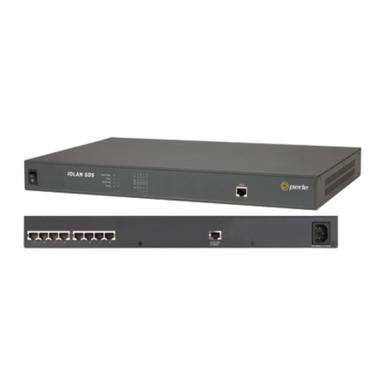
Getting to Know Your Device Server 2-Port This section describes the components found on the Device Server 2-port models. Console/Serial Reboot/Reset to Mode Switch Factory Defaults Power Supply Ethernet Interface Power LAN Connection LAN Activity Serial Activity Serial Connection The 2-port Device Server has two RJ45 serial connections. If you are using the 2-port Device Server, you can use an 8-pin connector if you do not need the power in (pin 1) or power out (pin 10) pins. -
Page 38: Rack Mount
Getting to Know Your Device Server Rack Mount This section describes the basic components of all rack mount Device Server models. This example uses an IOLAN SCS with dual ethernet and dual AC power. Console Port/LED View Server LEDs Line Serial Activity Console Port Power ON/OFF Serial/Ethernet View... -
Page 39: Led Guide
Getting to Know Your Device Server LED Guide Desktop Models The Device Server LEDs display the following information: Power/Ready—(Green/Red/Yellow) This LED starts out red at the beginning of power up. If this LED remains red, indicates that there is a critical error (see Hardware Problems on page 313). -
Page 40: Console Mode Vs. Serial Mode: Desktop Models
Powering Up the Device Server Console Mode vs. Serial Mode: Desktop Models You will notice a little switch at the back of the desktop Device Server models for switching the Device Server to either Console or Serial mode. Note that the Extended Temperature models have two switches, Switch 1 is used for Console mode and Switch 2 is unused. -
Page 41: I/O Models
Setting Jumpers I/O Models Before you attach the Device Server to your network or try to configure it, we suggest that you power it up to verify that it works properly. To power up the Device Server, perform the following steps: Unplug the power plugable terminal block from the Device Server. -
Page 42: 1-Port Device Server Rj45
Setting Jumpers 1-Port Device Server RJ45 To change the settings, do the following: Unplug the Device Server from the electrical outlet and disconnect everything from the box. Open the case by unscrewing the two side screws, one on each side, and lifting off the top of the case. -
Page 43: 1-Port Device Server Db9
Setting Jumpers 1-Port Device Server DB9 To change the settings, do the following: Unplug the Device Server from the electrical outlet and disconnect everything from the box. Open the case by unscrewing the two side screws, one on each side, and lifting off the top of the case. -
Page 44: 2-Port Device Server
Setting Jumpers 2-Port Device Server To change the settings, do the following: Unplug the Device Server from the electrical outlet and disconnect everything from the box. Open the case by unscrewing the two side screws, one on each side, and lifting off the top of the case. -
Page 45: 4-Port Desktop Device Server
Setting Jumpers 4-Port Desktop Device Server To change the settings, do the following: Unplug the Device Server from the electrical outlet and disconnect everything from the box. Open the case by unscrewing the two side screws, one on each side, and lifting off the top of the case. -
Page 46: Digital I/O Module
Setting Jumpers Digital I/O Module Device Servers that have Digital I/O have an input/output jumper that must be set for each channel and must match the software configuration for each channel. Depending on the model, the placement of the digital I/O board can change, so the diagram below shows how to set jumper for any digital board.To change the settings, do the following: Detach the Device Server from the electrical power source and disconnect everything from the box. -
Page 47: Analog Input Module
Wiring I/O Diagrams Analog Input Module Device Servers that have Analog Input have a voltage/current jumper that must be set for each channel and must match the software configuration for each channel. To change the settings, do the following: Detach the Device Server from the electrical power source and disconnect everything from the box. -
Page 48: Digital Input Dry Contact
Wiring I/O Diagrams Digital Input Dry Contact If you are using a dry contact for your Digital input, for channel D1 connect one wire to D1 and the other wire to COM. The power source is supplied by the COM (common) connector. Power Source Digital Output Sink... -
Page 49: Analog Input
Wiring I/O Diagrams Analog Input Make sure the Analog jumpers support the software setting; see Analog Input Module on page 47 jumper settings. Current To connect channel A1 with a 2-wire shielded cable, connect the positive wire to A1+, the negative wire to A1-, and optionally the shield to GND. -
Page 50: Rtd 2-Wire
Wiring I/O Diagrams RTD 2-Wire In a 2-wire RTD configuration, connect the excite wire to A1-, the return wire to A1+, and jumper the sense wire from A1s with a insulated wire going to A1+. sense RTD 3-Wire In a 3-wire RTD configuration, connect the return wire to A1+, the excite wire to A1-, and the sense wire to A1s. -
Page 51: Normally Closed Contact
Setting an Initial IP Address Normally Closed Contact To connect relay channel R1 for a circuit that is normally active, connect one wire to the COM (common) connector and one wire to the NC (normally closed) connector. Setting an Initial IP Address This section describes the different methods you can use to set the Device Server IP address. -
Page 52: Using Devicemanager
Setting an Initial IP Address Using DeviceManager To use the DeviceManager, you must first install it on a Windows 98/2000/NT/ME/Server 2003/XP operating system (Windows NT requires Service Pack 4 or later) that resides in the same network as the Device Server. The DeviceManager installation wizard can be found on the CD-ROM included in the Device Server package. -
Page 53: Using A Direct Connection
Setting an Initial IP Address Using a Direct Connection You can connect to the Device Server using a PC with a terminal emulation package, such as HyperTerminal or a terminal. Connect the Device Server to your PC or dumb terminal. Make sure the DIP switch is in Console mode (desktop models, this sets the Device Server serial port to EIA-232) or that you are connected to the dedicated Console port (rack mount models). -
Page 54: Using Dhcp/Bootp
Setting an Initial IP Address Using DHCP/BOOTP If you are using BOOTP, you need to add an entry for the Device Server that associates the MAC address (found on the back of the Device Server) and the IP address that you want to assign to the Device Server. -
Page 55: Using Arp-Ping
Setting an Initial IP Address Using ARP-Ping You can use the ARP-Ping (Address Resolution Protocol) method to temporarily assign an IP address and connect to your Device Server to assign a permanent IP address. To use ARP-Ping to temporarily assign an IP address: From a local UNIX/Linux host, type the following at the system command shell prompt: arp -s a.b.c.d aa:bb:cc:dd:ee:ff ®... -
Page 56: Serial Pinouts
Serial Pinouts Serial Pinouts DB25 Male This section defines the pinouts for the DB25 male connection used on the 1-port Device Server. The power out pin, Pin 9, is available in the SDS model only. Pin 1 Pin 13 Pin 14 Pin 25 The following table provides pinout information: EIA-485... -
Page 57: Db25 Female
Serial Pinouts DB25 Female This section defines the pinouts for the DB25 female connection used on the 1-port Device Server. The power out pin, Pin 9, is available in the SDS model only. Pin 13 Pin 1 Pin 25 Pin 14 The following table provides pinout information: EIA-485 EIA-485... -
Page 58: Rj45
Serial Pinouts RJ45 This section defines the pinouts for the RJ45 connection. 1-port, 2-port, and 4-port desktop Device Server models have a 10-pin RJ45 connector and all rack mount Device Server models have an 8-pin RJ45 connector. These pinouts do not apply to I/O models. Pin 1 Pin 10 The following table provides pinout information:... -
Page 59: Db9 Male (Serial Only)
Serial Pinouts DB9 Male (Serial Only) This section defines the pinouts for the DB9 male connection used on the 1-port Device Server that is serial only (not I/O). The following table provides pinout information: Pinout EIA-422/485 EIA-485 9-pin EIA-232 Full Duplex Half Duplex 1 (in) 2 (in) -
Page 60: Power Over Ethernet Pinouts
Power Over Ethernet Pinouts Power Over Ethernet Pinouts This section defines the pinouts for the RJ45 Ethernet connection used on the Device Server SDS P or Device Server SCS P models. Pin 1 Pin 8 The following table provides pinout information: Pinout Standard 802.3AF Unit-4 Wire... -
Page 61: Eia-232 Cabling Diagrams
EIA-232 Cabling Diagrams EIA-232 Cabling Diagrams This section shows how to create EIA-232 cables that are compatible with the Device Server. Terminal DB25 Connector The following diagrams show how the null modem cable should be configured when connecting to a terminal DB25. -
Page 62: Rj45
EIA-232 Cabling Diagrams RJ45 Terminal DB25 IOLAN RJ45 (DTE) 10-pin 8-pin (DSR) 20 (DTR) (RTS) 5 (CTS) (TxD) 3 (RxD) (RxD) 2 (TxD) (GND) 7 (GND) (CTS) 4 (RTS) (DTR) 6 (DSR) DB9 Male IOLAN DS1 Terminal DB25 DB9 Male (DTE) 3 (TxD) 3 (RxD) -
Page 63: Modem Db25 Connector
EIA-232 Cabling Diagrams Modem DB25 Connector The following diagrams show how a standard straight through cable should be configured when connecting to a DB25 modem. DB25 Male IOLAN DS1 Modem DB25 DB25 (DTE) (DCE) 2 (TxD) 2 (RxD) 3 (RxD) 3 (TxD) 4 (RTS) 4 (CTS) -
Page 64: Db9 Male
EIA-232 Cabling Diagrams DB9 Male IOLAN DS1 Modem DB25 DB9 Male (DCE) 1 (DCD) 8 (DCD) 2 (RxD) 3 (TxD) 3 (TxD) 2 (RxD) 4 (DTR) 20 (DTR) 5 (GND) 7 (GND) 6 (DSR) 6 (DSR) 7 (RTS) 4 (CTS) 8 (CTS) 5 (RTS) IOLAN Device Server User’s Guide, Version 2.5... -
Page 65: Chapter 3 Configuration Methods
Configuration Methods Chapter 3 Introduction This chapter provides information about the different methods you can use to configure the Device Server. Before you can configure the Device Server, you must assign an IP address to the Device Server. You can assign an IP address to the Device Server using one of the following methods: Using the DeviceManager as described in Using DeviceManager on page Using ARP-Ping as described in... -
Page 66: Webmanager
WebManager WebManager The WebManager is a web-browser based method of configuring/managing a Device Server. To access a Device Server through the WebManager, open up your web browser and type in the IP address of the Device Server that you want to manage/configure. A login screen will appear. Before you type in the Admin user password (the factory default password is ), select the For a... -
Page 67: Accessing The Menu
DHCP/BOOTP Accessing the Menu Menu access is available to any user whose is set to , and whose Line Service DSLogin User Service is set to . What the user sees depends on what the is set to: DSPrompt User Level Menu—Users with will only see the sessions that have been set up for them. -
Page 68: Snmp
Configuring the Device Server Through the MIB Once the IP address and user/community have been set, load the file from the perle-sds.MIB Device Server CD-ROM into your SNMP manager (this MIB works for all SDS, SCS, and STS models). Connect to the Device Server through your SNMP manager using its IP address to configure/manage the Device Server. -
Page 69: Iolan+ Interface
IOLAN+ Interface IOLAN+ Interface If you are an existing IOLAN+ user and would like to configure the Device Server using the IOLAN+ interface, you can type at the CLI command prompt to access the IOLAN+ iolan+ configuration menu. The IOLAN+ interface is supported on all Device Server SDS, SCS, and STS models up to and including 16-ports. - Page 70 IOLAN+ Interface When you select line Access , the following fields are not available on the Access Menu: ** Administrator ** ACCESS MENU REMOTE-ADMIN TTY Name Access Authentication Mode UDP Retries Interval [abcd ] [Local ] N/A [Raw [abcdef ] [Local ] N/A [Raw ________________________________________________________________________________...
- Page 71 IOLAN+ Interface When you select access Remote access sites. , the following fields are not available on the Remote Access Systems Screen: ** Administrator ** REMOTE ACCESS SYSTEMS SCREEN REMOTE-ADMIN Sitename User name Password Device type Service type Inactivity Phone number Login-script ________________________________________________________________________________ Service type...
- Page 72 IOLAN+ Interface When you select server , the following fields are not available on the Server Configuration menu: ** Administrator ** SERVER CONFIGURATION REMOTE-ADMIN Name [wchiewsds2 Debug mode IP address [172.16.22.7 Subnet mask [255.255.0.0 Ethernet address (00:80:d4:88:88:88) Ethernet speed [AUTO Language [English Identification...
-
Page 73: Chapter 4 Configuring The Device Server
Configuring the Device Server Chapter 4 Introduction This chapter provides general information about configuring the Device Server for your production environment. Although this chapter is not specific to any configuration method, there should be enough information that you can apply the information to any of the configuration methods. When you are configuring the Device Server, remember that none of your configuration changes will be permanent until you submit/apply your changes, save to FLASH, and reboot the Device Server. -
Page 74: Device Server Services
Configuring the Device Server Device Server Services In order to be as flexible and accessible as the Device Server is, it can run several predefined daemon and client applications. The Device Server can run the following daemon applications: TelnetD SPCD (the TruePort daemon) DeviceManagerD HTTPD HTTPSD... -
Page 75: Hardware Configuration
Configuring the Device Server Hardware Configuration Configure the Ethernet interface that is connecting the Device Server to the LAN and the serial cable that is connecting the Device Server to the serial device. Ethernet Connection You need to know the Ethernet interface speed and duplex as follows, unless you are using the Auto detect option: 10 Mbps half or full duplex 100 Mbps half or full duplex... -
Page 76: Local Port Buffering
Configuring the Device Server Local Port Buffering Port buffer information for the serial port can be viewed after successful connection to a device on a serial port. The user can toggle between communicating to the device on the serial port and viewing the port buffer data for that device by entering a configurable string (default ~view). -
Page 77: Modbus Configuration
Modbus Configuration Modbus Configuration This sections provides a brief overview of the steps required to configure a Device Server for your Modbus environment. You can read the Modbus Gateway Settings on page 78 Modbus Line Settings on page 79 sections for more specific information about the Modbus settings. Overview Configuring a Master Gateway To configure a Master Gateway (Modbus Master resides on the serial side of the Device Server), do... -
Page 78: Modbus Gateway Settings
Modbus Configuration Modbus Gateway Settings The scenarios in this section are used to illustrate how the Modbus Gateway settings are incorporated into a Modbus device environment. Depending on how your Modbus Master or Slave devices are distributed, the Device Server can act as both a Slave and Master Gateway(s) on a multiport Device Server or as either a Slave or Master Gateway on a single port Device Server. -
Page 79: Modbus Line Settings
Modbus Configuration Modbus Line Settings Modbus Master Settings When you have Modbus Masters on the serial side of the Device Server, configure the Line as a Modbus Master. If you also have a Modbus serial Slave on the same serial network as the serial Modbus Master that communicates with that serial Master, do not define its UID in the Remote Slave IP Mappings settings, or the Modbus serial Slave may not function properly. -
Page 80: Example Scenario
Modbus Configuration Example Scenario The following example describes the settings that you would configure to set up a Modbus environment on a multiport Device Server, where the Modbus Master resides on a serial port/line connected to the Device Server. This scenario assumes two things, that the (the Service ModbusD Modbus daemon) is enabled and that the default... - Page 81 Modbus Configuration The Device Server will send a request and expect a response from a Modbus Slave with an IP Address of 10.10.10.11 on Port 502 with UID 22 and from Modbus Slave with and IP Address of 10.10.10.12 on Port 502 with UID 23 (remember when is set to , the Device Range Mode...
-
Page 82: Email Notification
Email Notification Email Notification Email notification can be set at the Server and/or Line levels. You can set email notification at these levels because it is possible that the person who administers the Device Server might not be the same person who administers the serial device(s) attached to the Device Server port. -
Page 83: Users Connecting To Serial Devices
Users Connecting to Serial Devices Users Connecting to Serial Devices For a user to connect to the serial device connected to the Device Server from the LAN, the Line must be set to . The user will either access the serial device directly Service Rev Telnet Rev SSH... -
Page 84: Connecting Through The Device Server
Setting Up Lines Connecting Through the Device Server When a user connects through the Device Server, that user can be authenticated either locally or externally and is usually set up with a that, once authentication is completed User Service successfully, passes the user onto the specified host. Therefore, the Line Service is set to DSLogin... -
Page 85: Virtual Modems
Setting Up Lines Virtual Modems is a feature of the Device Server that provides “modem like” communication between two Vmodem Device Servers on a network or between a Device Server and a host. This feature behaves like two modems connected across a telephone line. Typically, you use the Vmodem feature when you have multiple devices communicating with a central site. -
Page 86: Udp
Setting Up Lines When you configure , you are setting up a range of IP addresses and a port number that you will use to send UDP data to or receive UDP data from. For example: The UDP configuration window, taken from the DeviceManager, is configured to: UDP Entry 1 All hosts that have an IP address that falls within the range of 172.16.1.1... -
Page 87: Ppp Dial On Demand
Setting Up Lines PPP Dial On Demand If you want to configure a line to use PPP dial on demand, do the following: Create an entry for the modem and its initialisation string. Set the Line Service Set the parameter to , enter the that the modem will be calling, and Line Dial... -
Page 88: Printers
Setting Up Lines Printers Remote Printing Using LPD When setting up a serial line that access a printer using LPD, do the following: Set the Line Service Printer and configure the Speed Flow Control Stop Bits Parity , and parameters so that they match the printer’s port settings. Bits Save your settings and kill the line. -
Page 89: Serial Tunnel Settings
Setting Up Users Serial Tunnel Settings The purpose of the serial is to allow two Device Servers that are Line Service Client/Server Tunnel connected back-to-back over Ethernet to virtually link two serial ports, based on RFC 2217. The serial device that initiates the connection is the Client Tunnel and the recipient is the Server Tunnel... -
Page 90: User Levels
Setting Up Users User Levels There are four User Levels Admin Normal Restricted , and Menu . Setting up users is only necessary when the users are actually connecting to the Device Server. Oftentimes, the Device Server is used as a gateway to a network and the user never actually logs into the Device Server itself. Users who do log into the Device Server ( Line Service set to... -
Page 91: Reverse Sessions And Multisessions
Setting Up Users Reverse Sessions and Multisessions (2 Port+ only) The interaction between reverse sessions and multisessions is somewhat complex, so the definition of each parameter is provided to give you a context for their interaction. Reverse Session—The definition of a Reverse Session is a TCP connection to a TCP port (defined in the Line configuration as the ) on a line that is configured for DS Port... -
Page 92: Configuring Network Options
Configuring Network Options Configuring Network Options Hosts This is probably one of the first Device Server options you want to configure, since so many other configuration options require a preconfigured host. You can use any host name you want, since the host name is used only by the Device Server. -
Page 93: Dns/Wins
Device Server; this can be done in the DeviceManager, WebManager, CLI, or Menu. You must then load the perle-sds.MIB (found on the CD-ROM packaged with the Device Server) file into your SNMP manager before you connect to the Device Server. -
Page 94: Keys And Certificates
Keys and Certificates Keys and Certificates When you are using SSH, SSL/TLS, LDAP, or HTTPS, you will need to install keys and/or certificates or get server keys in order to make those options work properly. All certificates need to be created and all keys need to be generated outside of the Device Server, with the exception of the Device Server SSH Public keys, which already exist in the Device Server. -
Page 95: Users Passing Through The Device Server Using Ssh (Dir/Sil)
Keys and Certificates Users Passing Through the Device Server Using SSH (Dir/Sil) In the following example, users are connecting to servers on the LAN through a serial device (a modem). The Line Service is set to DSLogin and the User Service is set to , therefore, users first log into the Device Server and then are connected to a specified host (configured for the user... -
Page 96: Language Support
Language support Language support Two language files, in addition to English, are supplied on the supplemental CD, French and German. You can use any of these language files to create a translation into a language of your choice. You can download the language file (whether the language is supplied or translated) into the Device Server and select the option of... -
Page 97: Translation Guidance
Language support Translation Guidance To help you with your translation, of supplied ASCII text language files we offer the following guidance: The Device Server will support languages other than English (and the supplied German and French languages). The English language file, , displays the character length of english.txt each line at the beginning of the line. -
Page 98: Downloading Terminal Definitions
Downloading Terminal Definitions Downloading Terminal Definitions All terminal types can be used on the Device Server. Some terminal types which are not already defined in the Device Server, however, are unable to use Full Screen mode (menus) and may not be able to page through sessions properly. - Page 99 Downloading Terminal Definitions For example: term=AT386 | at386| 386AT |386at |at/386 console acsc=jYk?lZm@qDtCu4x3 bold=\E[1m civis= clear=\E[2J\E[H cnorm= cup=\E[%i%p1%02d;%p2%02dH rev=\E4A rmacs=\E[10m rmso=\E[m smacs=\E[12m smso=\E[7m page= circ=n Note: As you can see from the example, capabilities which are not defined in the terminfo file must still be included (albeit with no value).
-
Page 100: Tftp Configuration
TFTP Configuration TFTP Configuration Note: TFTP file transfers send via UDP packets. When the packet delivery is interrupted for any reason and a timeout occurs, that packet is resent if the retry count allows it. Therefore, if a very large file is being transferred and is interrupted, the entire file is not resent, just the part of the file and was not received. -
Page 101: Dhcp/Bootp
DHCP/BOOTP DHCP/BOOTP You can use DHCP/BOOTP to perform the following actions on a single or multiple Device Servers on bootup: auto-configure with minimal information; for example, only an IP address auto-configure with basic setup information (IP address, subnet/prefix bits, etc.) download a new version of firmware download a full configuration file DHCP/BOOTP is particularly useful for multiple installations: you can do all the Device Server’s... -
Page 102: Slip Vs. Ppp
IPv6 Support. SLIP does not support IPv6, but PPP does. Creating Custom Applications You can create custom applications for the Device Server by using the Perle SDK. See the SDK Programmer’s Guide (the SDK and guide are found on the Perle website at ) for information about the functions that are www.perle.com/downloads/index.shtml... -
Page 103: Alarms
I/O Model Features Alarms Analog and Temperature input models support an Alarm mechanism in which you can specify up to five severity levels of alarm triggers and clear levels; the alarm triggers/clear levels can activate in either increasing or decreasing severity levels. The Digital Input supports an Alarm mechanism based on a trigger of either active input or inactive input and can be cleared either manually or automatically (when the trigger condition goes inactive or active, respectively). -
Page 104: Udp Unicast Example
I/O Model Features Digital/Relay Data The digital data is in bit format, 1 meaning On and 0 (zero) meaning Off. Each channel has its own bit, in least significant bit order. Length *Data Data (1 Byte, one bit for each channel) Exists 2 Bytes 1 Byte... -
Page 105: Modbus Serial Application Connected To The Network
I/O Model Features Modbus Serial Application Connected to the Network If you want to access the I/O from a LAN connection, you can install TruePort on the PC running the Modbus serial application as described in TruePort on page 108 and connect to the Device Server over the network. -
Page 106: A4/T4 Registers
I/O Model Features A4/T4 Registers The following registers are supported by the Device Server A4 and T4 Input models: Data Model A1/T1 A2/T2 A3/T3 A4/T4 Holding Registers: MB_REG_HR_AI_CLEAR_ALARM_LATCH 2049 2050 2051 2052 MB_REG_HR_AI_CLEAR_MAX 2113 2114 2115 2116 MB_REG_HR_AI_CLEAR_MIX 2177 2178 2179 2180 Input Registers:... -
Page 107: D4/D2R2 Registers
I/O Model Features Data Model D1/R1 D2/R2 R/W MB_REG_IR_MIN_RAW 2087 2119 2151 2183 ----- ----- MB_REG_IR_MAX_RAW 2088 2120 2152 2184 ----- ----- MB_REG_IR_ALARM_LEVEL 2089 2121 2153 2185 ----- ----- *For DI alarm state read will get state, write will clear alarm. D4/D2R2 Registers The following coils and registers are supported by the Device Server D4 and D2R2 I/O models: Data Model... -
Page 108: Trueport
If you have a custom application that talks to a serial port, you can use TruePort as a virtual serial port to communicate with the Device Server over the network to access I/O data using the Perle API. You also have the option of enabling SSL as a security option to encrypt the data that is communicated between the Device Server and the host machine (SSL/TLS must be configured in the Server settings and on the TruePort host). -
Page 109: Digital Channels
I/O Model Features Digital Channels You can configure the Digital I/O channels for either input or output, making the Device Server flexible in your production environment. Jumpers must be set to correspond with the software setting of either Input or Output; see Digital I/O Module on page 46 for jumper settings. -
Page 110: Digital Output
When one of the industrial freezer doors are left open for more than five minutes, the Monitoring Application (using the Perle API) starts the Digital output sink, causing the strobe light on top of the offending freezer to activate. -
Page 111: Temperature Channels
I/O Model Features Temperature Channels Temperature input channels monitor RTD or thermocouple temperature sensors. You can also configure severity alarms that can send an email, a syslog message, and/or an SNMP when an alarm is triggered or cleared; See Alarms on page 103 for more information about the alarms. -
Page 112: Analog Channels
(monitored by an Analog channel) a syslog message is sent to the Monitoring Application. The Monitoring Application then sends a command to the Device Server via the Perle API that causes the Relay channel to activate an internal freezer dehumidifier. The relay is turned off when the Analog channel sends a clear syslog message to the Monitoring Application and the Relay channel is deactivated. -
Page 113: Relay Channels
I/O Model Features Relay Channels Relay output channels work as a physical on/off switch, and are used to drive higher voltage devices with a lower controlling voltage. You can configure the following Relay output channel options: You can choose to manually activate/deactivate the Relay output. You can choose to manually activate/deactivate the Relay output and then specify that the Relay output will either pulse (you get to specify the active and inactive pulse times) continuously or for a specified number of pulse counts. -
Page 114: Calibrating Analog Input
I/O Model Features Calibrating Analog Input To calibrate an Analog input channel, read the section that applies to the type of input you are calibrating. Note that calibration will be done for the active channel configuration; for example, if Channel A1 is set to voltage, you cannot calibrate it for current. The voltage range configured for this channel will also dictate what is being calibrated. -
Page 115: Chapter 5 Using The Devicemanager
Using the DeviceManager Chapter 5 Introduction This chapter provides information about configuring/managing the Device Server using the DeviceManager. It is assumed that the DeviceManager has already been installed; if you still need to install the DeviceManager, see Using DeviceManager on page Starting a New Session When you start the DeviceManager application, the New Session window is displayed. -
Page 116: Managing A Device Server
Starting a New Session Managing a Device Server You can connect to Device Servers or assign a temporary IP address to a new Device Server. Whenever you connect to a Device Server through the DeviceManager, you connect as the Admin user and must supply the password for the Admin user. -
Page 117: Assigning A Temporary Ip Address To A New Device Server
Starting a New Session Assigning a Temporary IP Address to a New Device Server If your network does not use DHCP/BOOTP, you can temporarily assign an IP address to a Device Server that is connected to your local network segment, for the purpose of connecting to it and downloading a configuration file (containing a permanent IP address). -
Page 118: Creating A New Device Server Configuration
Connecting to a Device Server Creating a New Device Server Configuration If you selected the New Configuration radio button, the New Configuration window is displayed. Select the Device Server model for which you want to create a new configuration file. Opening an Existing Configuration File If you selected the radio button, a browse window is opened so you can select... -
Page 119: Managing A Device Server
Managing a Device Server Managing a Device Server Once you are connected to a Device Server, you can edit its configuration, download a new configuration, save the configuration to file, perform administrative tasks, and view statistics about the Device Server and its network environment. DeviceManager Work Flow When you connect to a Device Server, the Device Server’s configuration is automatically uploaded to the DeviceManager. -
Page 120: Configuring The Server
Configuring the Server Configuring the Server The following sections describe how to configure the Device Server’s server parameters. In each of the sections, the SCS8 model is being used; this means that what you configure can differ from what’s shown, although all of your configuration parameters will be explained. Configuring the Main Server Window When you select Server Configuration... -
Page 121: Services
Configuring the Server Services Services are either daemon or client processes that run on the Device Server. You can disable any of the services for security reasons. If you disable the DeviceManagerD service, you will not be able to use DeviceManager to connect to a Device Server. TelnetD Telnet daemon process in the Device Server on port 23. -
Page 122: Configuring Advanced Server Settings
Configuring the Server Configuring Advanced Server Settings In the Server window, the following window is displayed when you click the Advanced button. Configure the appropriate parameters: OEM Login When set, and a custom language file is in use, the login prompt will use the string defined in the language file as the login prompt instead of the default prompt, login:... - Page 123 Configuring the Server Session Escape A configurable string that allows access to a port to view the multisession String screen options, allowing the various options while accessing the particular port on the Device Server. You can specify control (unprintable) codes by putting the decimal value in angle brackets <...
-
Page 124: Configuring Port Buffering
NFS host for decrypting the data to a readable format. The Decoder utility software can be found on the installation CD-ROM and on the website. www.perle.com Time Stamp Enable/disable time stamping of the port buffer data. Configuring TruePort Baud... -
Page 125: Configuring Authentication
Configuring the Server Configuring Authentication The Device Server can authenticate a user locally or through an external authentication server, based , or locally by just a when the option is enabled. This User Name Password Password Guest is different from authorization, which can restrict a user’s access to the network (although this can be done through the concept of creating sessions for a user, see Sessions on page 90 for more... -
Page 126: Radius
Configuring the Server RADIUS RADIUS is an authentication method that the Device Server supports that can send back User information; see Appendix A, RADIUS on page 297 for more information on the parameters User that can be sent back by RADIUS. The RADIUS configuration window is displayed when you click on RADIUS Settings button. -
Page 127: Kerberos
Configuring the Server Kerberos The Kerberos configuration window is displayed when you click on button. Kerberos Settings Configure the following parameters: Realm The Kerberos realm is the Kerberos host domain name, in upper-case letters. KDC Domain The name of a host running the KDC (Key Distribution Center) for the specified realm. -
Page 128: Tacacs
Configuring the Server TACACS+ TACACS+ is an authentication method that the Device Server supports that can send back User information; see Appendix B, TACACS+ on page 305 for more information on the parameters User that can be sent back by TACACS+.The TACACS+ configuration window is displayed when you click on TACACS+ Settings button. -
Page 129: Securid
Configuring the Server Accounting Port The port number that TACACS+ listens to for accounting requests. The default port number is 49. Accounting Secret The TACACS+ shared secret is used to encrypt/decrypt TACACS+ packets in communications between two devices. The shared secret may be any alphanumeric string. -
Page 130: Nis
Configuring the Server The NIS configuration window is displayed when you click on button. NIS Settings Configure the following parameters: NIS Domain The NIS domain name. Primary NIS Host The primary NIS host that is used for authentication. Secondary NIS Host The secondary NIS host that is used for authentication, should the primary NIS host fail to respond. -
Page 131: Configuring The Ssh Server
Configuring the Server Console Baud Rate For Device Server models that have a dedicated console port, specifies the baud rate of the line connected to the console port. Console Flow For Device Server models that have a dedicated console port, defines whether Control the data flow is handled by using software ( ), hardware (... -
Page 132: Ssl/Tls Settings
Configuring the Server Breakstring The break string used for inband SSH break signal processing. A break signal is generated on a specific serial port only when the server's break option is enabled and the user currently connected using reverse SSH has typed the break string exactly. -
Page 133: Cipher Suite
Configuring the Server Cipher Suite You can set up cipher rules to govern the encryption that will be used for the SSL/TLS connection. Configure the following parameters: Encryption Select the type of encryption that will be used for the SSL connection: Any—Will use the first encryption format that can be negotiated. -
Page 134: Validation Criteria
Configuring the Server Validation Criteria If you choose to configure validation criteria, then the information in the peer SSL/TLS certificate must match exactly the information configured in this window in order to pass peer authentication and create a valid SSL/TLS connection. Configure the following parameters: Country A two character country code;... -
Page 135: Configuring The Modbus Gateway
Configuring the Server Configuring the Modbus Gateway The Advanced Gateway Settings are global to both Master and Slave Modbus Gateways. There are no parameters that are specific to only the Modbus Master Gateway, as there is for the Modbus Slave Gateway. -
Page 136: Configuring Server Email Alerts
Configuring the Server Remapped Used for single device/port operation. Older Modbus devices may not include a UID in their transmission header. When this option is selected, you can specify the UID that will be inserted into the message header for the Modbus slave device. -
Page 137: Pci Configuration
PCI modem line. Custom App You can create a custom application that can run on the Device Server using the Perle SDK. Configure the following parameter: Program The name of the SDK program executable that has been already been... -
Page 138: Configuring Lines
Configuring Lines Configuring Lines When you configure the Device Server , you are specifying how the port will be used and Line accessed. You can always make changes to Line parameters by clicking the Save Line button, selecting , and then selecting Configuration Tools Download Configuration to Unit... - Page 139 Configuring Lines Serial Interface Specifies the type of line that is being used with the Device Server. Select either EIA-232, EIA-422, or EIA-485. The SCS/STS models support only EIA-232. Speed Specifies the baud rate of the line; keep in mind that speed is affected by the length of the cable.
-
Page 140: Advanced Line Settings
Configuring Lines Advanced Line Settings You can configure these advanced settings for a line. Configure the appropriate parameters: Pages line service, this is the number of video pages the terminal DSLogin supports. Valid values are 1-7. The default is pages. User DSLogin line service, makes this a line that is dedicated to the specified... - Page 141 Configuring Lines Break Specifies how a break is interpreted: None—The Device Server ignores the break key completely and it is not passed through to the host. This is the default setting. Local—The Device Server deals with the break locally. If the user is in a session, the break key has the same effect as a hot key.
-
Page 142: Service Settings
Configuring Lines Hotkey Prefix The prefix that a user types to lock a line or redraw the Menu. The default value is , which corresponds to ) (hex value 02 would be hex 01 Ctrl-a Ctrl-b (^b), etc.): —(Lowercase L) Locks the line until the user unlocks it. The user is ^a l prompted for a password (any password, excluding spaces) and locks the line. -
Page 143: Raw Settings
Configuring Lines Raw Settings When the is set to , data is sent through the connection in its Line Service Direct Silent Raw original format. This raw TCP/IP connection is initiated from the Device Server to the configured host. The Client Tunnel Line Service also uses settings;... -
Page 144: Bidir Settings
Configuring Lines Line Mode When , keyboard input is not sent to the remote host until is pressed, Enter otherwise input is sent every time a key is pressed. Default is Map CR to CRLF Maps carriage returns (CR) to carriage return line feed (CRLF). The default value is Interrupt Defines the interrupt character. -
Page 145: Rlogin Settings
Configuring Lines Rlogin Settings When the is set to , data is sent in its original Line Service Direct Silent Rlogin DSLogin format. This rlogin session is initiated from the Device Server to the configured host. Configure the following parameters: Terminal Type Type of terminal attached to this line;... - Page 146 Configuring Lines Subnet Mask The network subnet mask. For example, 255.255.0.0. If your user is authenticated by RADIUS and the RADIUS parameter is set Framed-Netmask in the RADIUS file, the Device Server will use the value in the RADIUS file in preference to the value configured here.
-
Page 147: Ppp Settings
Configuring Lines PPP Settings When the is set to , a PPP connection is established between the Line Service DSLogin Device Server and a remote user. This connection can be initiated by either the Device Server or the remote user. Configure the following parameters: IPv4 Local IP The IPV4 IP address of the Device Server end of the PPP link. - Page 148 Configuring Lines IPv6 Remote The remote IPv6 interface identifier of the remote end of the PPP link. Choose Interface Identifier an address that is part of the same network or subnetwork as the Device Server. If you set the parameter , the Device Server IP Address Negotiation will ignore the remote IP address value you enter here and will allow the...
- Page 149 Configuring Lines User Complete this field only if you have specified (security CHAP protocols) in the field, and Security you wish to dedicate this line to a single remote user, who will be authenticated by the Device Server, or you are using the Device Server as a router (back-to-back with another Device Server).
- Page 150 Configuring Lines Remote Password Complete this field only if you have specified (security CHAP protocols) in the field, and Security you wish to dedicate this line to a single remote user, and this user will be authenticated by the Device Server, or you are using the Device Server as a router (back-to-back with another Device Server) Remote password means the following:...
- Page 151 Configuring Lines Challenge Interval The interval, in minutes, for which the Device Server will issue a CHAP re-challenge to the remote end. During CHAP authentication, an initial CHAP challenge takes place, and is unrelated to CHAP re-challenges. The initial challenge takes place even if re-challenges are disabled. Some PPP client software does not work with CHAP re-challenges, so you might want to leave the parameter disabled in the Device Server.
-
Page 152: Ssh Client Settings
Configuring Lines SSH Client Settings When the is set to , the data will be sent through the Line Service Direct Silent SSH DSLogin connection in an SSH session. This session will be initiated by the Device Server to the configured host. -
Page 153: Udp Settings
Configuring Lines SSH 2 Ciphers Select the order of negotiation for the encryption method (ciphers) that the Device Server will use for the SSH version 2 connection: 3DES Blowfish Arcfour CAST An authentication method used by SSH version 1 and 2. Use RSA authentication for the SSH session. -
Page 154: Vmodem Settings
Configuring Lines VModem Settings When the is set to , the Device Server acts as a virtual modem. After a virtual Line Service VModem modem connection is established, data will flow in both directions in its original format. Configure the following parameters: Host Name The target host name. -
Page 155: Ssl/Tls Settings
Configuring Lines SSL/TLS Settings SSL/TLS can be configured for any service that uses a raw connection, such as Dir/Sil/Rev Raw, Vmodem, and Bidir. SSL/TLS can also be configured for DSLogin, which is used when the User Service SSL-Raw is configured. The Server Tunnel Line Service requires no configuration unless you want to send the data encrypted using SSL/TLS;... -
Page 156: Cipher Suite
Configuring Lines Cipher Suite You can set up cipher rules to govern the encryption that will be used for the SSL/TLS connection. Configure the following parameters: Encryption Select the type of encryption that will be used for the SSL connection: Any—Will use the first encryption format that can be negotiated. -
Page 157: Validation Criteria
Configuring Lines Validation Criteria If you choose to configure validation criteria, then the information in the peer SSL/TLS certificate must match exactly the information configured in this window in order to pass peer authentication and create a valid SSL/TLS connection. Configure the following parameters: Country A two character country code;... -
Page 158: Server Tunnel Settings
Configuring Lines Server Tunnel Settings The purpose of the serial is to allow two Device Servers that are Line Service Client/Server Tunnel connected back-to-back over Ethernet to virtually link two serial ports. The serial device that initiates the connection is the Client Tunnel and the recipient is the Server Tunnel... -
Page 159: Modbus Slave Settings
Configuring Lines Modbus Slave Settings This window configures the parameters for Modbus Slaves residing on the serial side of the Device Server. See Modbus Configuration on page 77 for more information about how to configure the Device Server for a Modbus environment. Configure the following parameters: Modbus/RTU Select this option if the Modbus Master is configured using the Modbus/RTU... -
Page 160: Remote Ip Slave Mappings
Configuring Lines Append CR/LF When is selected, adds a CR/LF to the end of the transmission; Modbus/ASCII most Modbus devices require this option. The default is Remote IP Slave Click this button to launch the Remote Slave IP Settings window, where you Mappings Button can configure the TCP/Ethernet Modbus Slaves that the Modbus Master on the Line will communicate with. -
Page 161: Custom App Settings
Custom App Settings You can create a custom application that can run on a specific serial line in Device Server using the Perle SDK. Configure the following parameter: Program The name of the SDK program executable that has been already been... -
Page 162: Trueport Settings
Configuring Lines TruePort Settings When the is set to , data is sent through the connection in its original format. Line Service TruePort This raw TCP/IP connection can be initiated from the Device Server to the configured host or from the host to the Device Server, depending on the settings. -
Page 163: Configuring Line Email Alerts
Configuring Lines Configuring Line Email Alerts email alerts are specific to events that occur on the line. An email is sent to the specified Line recipient(s) when an event occurs that meets the criteria. Level Configure the following parameters: User Server Settings Determines whether you want the to inherit the settings from Line... -
Page 164: Packet Forwarding
Configuring Lines Packet Forwarding The Packet Forwarding feature allows you to control how the data coming from a serial device is packetized before forwarding the packet onto the LAN network. Configure the following parameters: Packet Definition This section allows you to set a variety of packet definition options. The first criteria that is met causes the packet to be transmitted. - Page 165 Configuring Lines Frame Definition This section allows you to control the frame that is transmitted by defining the start and end of frame character(s). If the internal buffer (1024 bytes) is full before the EOF character(s) are received, the packet will be transmitted and the EOF character(s) search will continue.
-
Page 166: Copying Line Settings To Another Line(S)
Configuring Lines Copying Line Settings to Another Line(s) On 4-port+ models, you can selectively copy the current line’s setting to another line(s). Click the button to display the Copy Line window. Save & Copy Line Configuration Check the boxes of the lines you want to copy the current line’s setting to or click to select Select All all the lines;... -
Page 167: Configuring I/O
Configuring I/O Configuring I/O This configuration entry will appear in the DeviceManager only when connected to a Device Server that supports I/O or when an I/O model configuration is selected. Global Settings The I/O Global Settings enable/disable options that support all I/O channels on your Device Server. Temperature Settings Temperature Scale Select the temperature scale that will be used to display temperature data, either Fahrenheit or Celsius. -
Page 168: Modbus Settings
These TruePort settings pertain specifically to using TruePort to allow serial Modbus Masters to access Device Server I/O data over the network or allowing a serial application to access the Device Server I/O data over the network using the Perle API (see API I/O Access Over TruePort on page for more information). - Page 169 Configuring I/O The I/O UDP settings window allows you to configure the UDP broadcast recipients. Configure the following parameters: UDP Entry When enabled, broadcasts I/O status (data) to the specified range of IP addresses. Start IP Address The first host IP address in the range of IP addresses (for IPV4 or IPV6) that the Device Server will listen for messages from and/or send messages to.
-
Page 170: Channels
Configuring I/O Channels Digital Output When the channel is set for digital output, either voltage is applied to the channel or the channel is grounded. Note that the internal jumpers must match the software setting and must be set to Output (by default, they are set to Input);... -
Page 171: Digital Input
Configuring I/O Pulse Mode When the , you can have it pulse in a manner or Output Pulse Continuous specify a pulse (each count consists of an active/inactive sequence). The Count default is Continuous Pulse Count The channel output will pulse for the specified number of times; each count consists of an active/inactive sequence. -
Page 172: Relays
Configuring I/O Invert Signal Inverts the actual condition of the I/O signal in the status; therefore, an inactive status will be displayed as active. Trigger When the trigger condition is met, triggers the specified alarm action. Triggers can be: Disabled—No alarm settings. This is the default. Inactive—When the expected Digital input is active, going inactive will trigger an alarm. - Page 173 Configuring I/O Output Specify how the channel output will be handled: Manual—You must manually manipulate the channel output. Pulse—Activates and deactivates the channel output activity in intervals after it is manually activated. Inactive-to-Active Delay—The channel output will remain inactive for the specified time interval after it is manually started.
-
Page 174: Analog
Configuring I/O Analog Analog channels monitor current/voltage input. Note that the internal jumpers must match the software setting (by default, they are set to Current); see Analog Input Module on page 47 to find out how to set the internal jumpers. Configure the following parameters: Enable Channel Enables the channel, allowing the settings to become active. -
Page 175: Basic Alarm Settings
Configuring I/O Basic Alarm Settings The basic Analog Alarm Settings window allows you to configure one severity alarm, whereas the advanced window allows you to configure up to five severity alarm levels. Configure the following parameters: Trigger alarm Specify the value that will trigger an alarm, the measurement is based on the when input value is Type Range... -
Page 176: Advanced Alarm Settings
Configuring I/O Advanced Alarm Settings The advanced Analog Alarm Settings window expands the basic alarm settings options to up to five severity levels. Configure the following parameters: Trigger Type If the , an alarm is triggered when the input drops below Trigger Type the specified value;... -
Page 177: Temperature
Configuring I/O Syslog Sends a message to syslog when an alarm is triggered or cleared. The syslog entry includes the severity level and the value that caused the alarm to trigger or clear. The syslog message is associated with Level Critical SNMP Sends an SNMP trap when an alarm is triggered or cleared. -
Page 178: Configuring Users
Configuring Users Configuring Users You can configure up to four users in the Device Server’s local user database for all DS, SDS, and SCS 1-port to 4-port desktop models, in addition to the Admin user. You can configure up to 48 users in the Device Server’s local user database for all STS models and 8-port+ SCS and SDS models, in addition to the Admin user. - Page 179 Configuring Users Hotkey Prefix The prefix that a user types to control the current session. The default value is , which corresponds to ) (hex value 02 would be Ctrl-b (^b), hex 01 Ctrl-a etc.): —To switch from one session to another, press and then the ^a number required session number.
- Page 180 Configuring Users Service The type of service that the user will use. Host IP When the User Service is set to Telnet Rlogin , or TCP_clear , the target host IP address. If 255.255.255.255 is specified in the configuration, the user will be prompted for an IP address or hostname.
-
Page 181: Configuring Line Access
Configuring Users Framed Used for , determines whether Van Jacobsen User Service PPP SLIP Compression Compression is used on the link. VJ compression is a means of reducing the standard TCP/IP header from 40 octets to approximately 5 octets. This gives a significant performance improvement, particularly when interactive applications are being used. -
Page 182: Configuring Sessions
Configuring Users Configuring Sessions You can configure user Sessions to limit the access the user has to the network and the way the user connects to a host. Users who are can define , in addition to Level Normal Admin Free Sessions using defined sessions. -
Page 183: Configuring The Network
Configuring the Network Configuring the Network The network configuration parameters define the network that the Device Server will be operating within. Configuring Hosts One of the first things you will probably want to configure is the hosts that the Device Server or Users will be interacting with, since most configuration windows require that the hosts already be configured. -
Page 184: Configuring Snmp
Configuring the Network Configuring SNMP If you are using the Device Server SNMP MIB-based configuration/management option, you can use the DeviceManager to easily set up SNMP users, traps, and communities. The Device Server supports the SNMP traps for restart and SNMP community authentication error. For more information on SNMP, see SNMP on page Configure the appropriate parameters:... -
Page 185: Configuring Tftp
Configuring the Network Configuring TFTP These parameters configure the TFTP settings for the Device Server’s connections to hosts (as opposed to the TFTP settings under , which configure the TFTP settings for the Tools Options DeviceManager’s connection to a Device Server). Configure the following parameters: Retry The number of times the Device Server will retry to transmit a TPFT packet... -
Page 186: Configuring Gateways
Configuring the Network Configuring Gateways You can configure gateways to allow the Device Server access to hosts that are not within the local network segment. Configure the following parameters: Host You can specify up to 20 hosts on desktop models and 49 hosts on rack mount models to act as gateways in your network. -
Page 187: Configuring Syslog
Configuring the Network Configuring Syslog You can configure where the system log messages are going to be sent and specify the lowest level message that the Device Server will send syslog messages for. Configure the following options: Primary Host The first preconfigured host that the Device Server will attempt to send system log messages to;... -
Page 188: Configuring Rip
Configuring the Network Configuring RIP You can configure the Routing Information Protocol (RIP) that will define the communication between the Device Server and the local network (this has no impact on the parameters that Routing can be set for PPP in both the configuration windows). -
Page 189: Configuring Time
Configuring Time Confirm Key Retype the MD5 key that is being used by your routers to verify that it was typed correctly. Configuring Time You can configure an SNTP server to automate the time in the Device Server and configure an automatic summertime (daylight savings time) time change. -
Page 190: Configuring Sntp Settings
Configuring Time Fixed End Date Sets the exact date and time in which the Device Server’s clock will end summer time hours and change to standard time. Recurring Start Sets the relative date and time in which the Device Server’s clock will change Date to summer time (daylight saving time) hours. -
Page 191: Configuring Administration Tasks
Configuring Administration Tasks Configuring Administration Tasks You can specify new configuration and firmware files that will go into effect the next time the Device Server is rebooted and a message of the day (MOTD) file, whose contents will be displayed when User’s log into the Device Server. -
Page 192: Configuring The Motd File
I/O Status/Control Configuring the MOTD File You can specify a file whose content will be displayed to users after they connect to the Device Server, but before they log in. The Device Server will retrieve the file content every time a user connects to the Device Server, so you can change the content of the file without reconfiguring it within the Device Server. -
Page 193: Statistics
Statistics Statistics After you are connected to a Device Server, you can view statistics about the Device Server and its network environment. This can help you to troubleshoot problems or can provide valuable information about the Device Server’s environment. Tools Saving a Configuration To File When you connect to a Device Server, the Device Server’s configuration is automatically uploaded to the DeviceManager. -
Page 194: Downloading Device Server Firmware
Tools Enter the following information for each Device Server that you want to configure with the same configuration file: IP Address Enter the IP address of the Device Server that you want to download the configuration to. Server Name The name of the Device Server. The Device Server name that you put in this field is passed into the configuration before it is downloaded to the Device Server and cannot be left blank. -
Page 195: Setting The Device Server's Date And Time
Tools Setting the Device Server’s Date and Time To set the Device Server’s system clock, select . The Set Date/Time Tools Set Unit Time/Date window is displayed. Configure the following parameters: Date The Device Server’s date. The format of the Device Server’s date is dependent on the Windows operating system and regional settings. -
Page 196: Resetting/Killing A Line
Tools Resetting/Killing a Line After you make changes to the Line configuration parameters and click the Apply button, you can reset/kill the line to test the changes by selecting . If you are connecting to a 1-port Tools Kill Line Device Server, you might be prompted to confirm to kill the line;... -
Page 197: Keys And Certificates
Tools Keys and Certificates You will need to download/upload keys and/or certificates if you are using: LDAP with Secure HTTP ( HTTPS SSL/TLS Keys and Certificates on page 94 for information on when you need to download/upload keys and/or certificates. Configure the following parameters: Key / Certificate Select the key or certificate that you want to download to the Device Server or... -
Page 198: Custom Files
Language support on page 96 for information on creating custom language files. Downloading a Custom App File You can download each custom application file, created with the Perle SDK, to the Device Server using this option. I/O Channels Calibrating Analog Channels Analog Input can be calibrated for Analog and Temperature Device Server models. -
Page 199: Resetting Calibration Data
Tools If you have not disabled confirmation messages ( Tools Options ), you will get prompted to verify channel calibration. Click to proceed with calibration. You are now prompted to apply 0 mA to the positive (+) and negative (-) terminals. Once that is done, click to proceed. - Page 200 Tools TFTP—Sets the TFTP options for communication between the DeviceManager and a Device Server. Configure the following parameters: Retry The number of times the Device Server will retry to transmit a TPFT packet to/from a host when no response is received. Enter a value between 0 and 5. The default is 5.
-
Page 201: Chapter 6 Command Line Interface
Command Line Interface Chapter 6 Introduction This chapter provides the command line interface (CLI) options available for the Device Server. The commands are grouped by function. CLI Conventions This section explains how to interpret the CLI syntax. If you are an existing IOLAN+ customer and would like to configure the Device Server in the native IOLAN+ interface, you can type the command to display and use the native IOLAN+ interface (you must have... -
Page 202: Command Shortcuts
CLI Conventions Command Shortcuts When you type a command, you can specify the shortest unique version of that command or you can press the key to complete the command. For example, the following command: set telnet-client map-to-crlf off can be typed as: set tel map off or, you can use the key to complete the lines as you go along:... -
Page 203: Server Commands
For Device Server models that have a dedicated console port, specifies the baud rate of the line connected to the console port. Set Custom-App Description You can create a custom application that can run on the Device Server using the Perle SDK. User Level Admin Syntax set custom-app server program-command-line <command>... -
Page 204: Set Port-Buffering
NOTE: When NFS encryption is enabled, the Decoder utility software is required to be installed on the NFS host for decrypting the data to a readable format. The Decoder utility software can be found on the installation CD-ROM and on the www.perle.com website. nfs-host... -
Page 205: Set Server
Server Commands Set Server Description Sets server parameters. User Level Admin Syntax set server [banner on|off] [break on|off] [bypass-password on|off] [domain <string>] [flush-on-close on|off] [line-menu-string <string>] [name <string>] [netmask <IPV4_address>][oem-login on|off] [password-limit <0-10>] [prompt-with-name on|off] [ip-filter on|off] [reverse-session-limit <1-5>] [session-escape-string <string>] [single-telnet on|off] set server internet [eth1|eth2] <IPV4_address>... - Page 206 Server Commands oem-login When set, and a custom language file is in use, the login prompt will use the string defined in the language file as the login prompt instead of the default prompt, login: password-limit The number of attempts a user is allowed to enter a password for a serial port connection (this applies to and Console mode connections).
-
Page 207: Set Ssl Server
Server Commands timeout The time, in seconds, that the Device Server will wait for a successful transmit or receipt of TFTP packets before retrying a TFTP transfer. Enter a value between 3 and 10. The default is seconds. ssl-passphrase This is the SSL/TLS passphrase used to generate an encrypted RSA/DSA private key. This private key and passphrase are required for both HTTPS and SSL/TLS connections, unless an unencrpyted private key was generated, then the SSL passphrase is not required. -
Page 208: Set Service
Server Commands locality Up to a 128 character entry for the location; for example, a city. This field is case sensitive in order to successfully match the information in the peer SSL/TLS certificate. organisation Up to a 64 character entry for the organisation; for example, Accounting. This field is case sensitive in order to successfully match the information in the peer SSL/TLS certificate. -
Page 209: Show Console
Server Commands sntp SNTP client process in the Device Server. httpsd HTTPS daemon process in the Device Server on port 443. syslog Syslog client process in the Device Server. dmgrd DeviceManager daemon process in the Device Server. If you disable this service, you will not be able to connect to the Device Server with the DeviceManager application. -
Page 210: Hardware Commands
Server Commands Hardware Commands Set Ethernet Description Sets the serial line speed and duplex. User Level Admin Syntax set ethernet [eth1|eth2] speed-and-duplex auto|10-half|10-full|100-half|100-full|1000-half|1000-full Options eth1|eth2 You must specify the Ethernet interface if you have an SCS model with dual Ethernet. auto|10-half|10-full|100-half|100-full|1000-half|1000-full Define the Ethernet connection speed at one of the following (desktop models don’t support 1000 Mbps):... -
Page 211: Show Ssh-Server
Server Commands authentication keyboard-interactive The user types in a password for authentication. compression Requests compression of all data. Compression is desirable on modem lines and other slow connections, but will only slow down things on fast networks. verbose Displays debug messages on the terminal. break-string The break string used for inband SSH break signal processing. - Page 212 Server Commands verify-peer Enable this option when you want the Validation Criteria to match the Peer Certificate for authentication to pass. If you enable this option, you need to download an SSL/TLS certificate authority (CA) list file to the Device Server. validation-criteria Any values that are entered in the validation criteria must match the peer certificate for an SSL connection;...
-
Page 213: Set Ssl Server Cipher-Suite
Server Commands Set SSL Server Cipher-suite Description Sets the default SSL/TLS cipher suite parameters. User Level Admin Syntax set ssl server cipher-suite option1|option2|option3|option4|option5 encryption any|aes|3des|des|arcfour|arctwo|none min-key-size 40|56|64|128|168|256 max-key-size 40|56|64|128|168|256 key-exchange any|rsa|edh-rsa|edh-dss|adh hmac any|sha1|md5 Options option1|option2|option3|option4|option5 Sets the priority of the cipher suite, with being highest priority and option1 option5... -
Page 214: Show Ssl
Server Commands Show SSL Description Shows the SSL/TLS settings/information. User Level Normal, Admin Syntax show ssl Modbus Commands Set Modbus Gateway Description Sets the authentication method for the Device Server. User Level Admin Syntax set modbus gateway [addr-mode embedded|re-mapped] [broadcast on|off] [char-timeout <number>] [req-next-delay <number>] [exceptions on|off] [idle-timer <number>] [mess-timeout <number>] [port <TCP/UDP_port>] [req-queuing on|off]... -
Page 215: Show Modbus
Server Commands req-queuing When enabled, allows multiple, simultaneous messages to be queued and processed in order of reception. The default is remapped-id Specify the UID that will be inserted into the message header for the Slave Modbus serial device. Valid values are 1-247. When enabled, Modbus Slave Gateway messages to remote TCP Modbus Masters are encrypted via SSL/TLS. -
Page 216: Set Authentication Local
Server Commands Set Authentication Local Description Configures local authentication settings. When you configure the Device Server to authenticate user’s locally, you can require that the user’s be configured in the User table or you can allow Guest users, who can log into the Device Server using any ID, but must know the configured password. -
Page 217: Set Authentication Nis
Server Commands Enables/disables the Transport Layer Security (TLS) with the LDAP host. tls-port Specify the port number that LDAP will use for . The default is port 636. Set Authentication NIS Description Sets NIS authentication parameters. User Level Admin Syntax set authentication nis [domain <string>] [primary <config_host>] [secondary <config_host>] Options... -
Page 218: Set Authentication Radius
Server Commands Set Authentication RADIUS Description Sets RADIUS parameters. User Level Admin Syntax set authentication radius [accounting on|off] [acct-authenticator on|off] [acct-port <UDP_port>] [auth-port <UDP_port>] [retry <integer>] [timeout <integer>] Options accounting Enables/disables RADIUS accounting. acct-authenticator Enables/disables whether or not the Device Server validates the RADIUS accounting response. -
Page 219: Set Authentication Securid
Server Commands Set Authentication SecurID Description Configures SecurID authentication settings. User Level Admin Syntax set authentication securid primary [host <config_host>] [port <TCP_port>] [encryption des|sdi] [legacy on|off] set authentication securid replica [host <config_host>] [port <TCP_port>] [encryption des|sdi] [legacy on|off] set authentication securid reset secret Options primary host The first SecurID server that is tried for user authentication. -
Page 220: Trueport Baud Commands
Server Commands TruePort Baud Commands Set TruePort Remap-Baud Description Sets the TruePort baud remapping values. User Level Admin Syntax set trueport remap-baud 50|75|110|134|150|200|300|600|1200|1800|2400|4800|9600|19200| 38400 50|75|110|134|150|200|300|600|1200|1800|2400|4800|9600|19200| 38400|57600|115200|230400|28800|[custom <baud_rate] Options 50|75|110|134|150|200|300|600|1200|1800|2400|4800|9600|19200|38400 The configured baud rate of the TruePort client. 50|75|110|134|150|200|300|600|1200|1800|2400|4800|9600|19200|38400| 57600|115200|230400|28800|[custom <baud_rate>] The actual baud rate that runs between the Device Server and the connected serial device. -
Page 221: Show Email-Alert Server
Description Restarts a line. On 2+ port Device Servers, you can specify a port number and then a range of ports; for example, . This also resets the Perle kill line 4, 10-13, 15 PCI modem card on SDS M models. 1-port models use simply... -
Page 222: Logout
User Commands Logout Description Logs the user out from the Device Server. User Level Restricted, Normal, Admin Syntax logout Menu Description Switches from the CLI mode to the Menu. User Level Restricted, Normal, Admin Syntax menu Ping Description Pings the specified host/IP address. User Level Normal, Admin Syntax ping <hostname/IP_address>... -
Page 223: Set Termtype
User Commands Set Termtype Description Sets the type of terminal being used for the current session. User Level Normal, Admin Syntax set termtype wyse60|vt100|ansi|dumb|tvi925|ibm3151te|vt320|hp700|term1|term2| term3 Option wyse60|vt100|ansi|dumb|tvi925|ibm3151te|vt320|hp700|term1|term2|term3 Specifies the type of terminal connected to the line: Dumb WYSE60 VT100 ANSI TVI925 IBM3151TE VT320 (specifically supporting VT320-7) -
Page 224: Set User Session
User Commands routing Determines the routing mode used for RIP packets on the PPP and SLIP interfaces. Values are: None—RIP packets are neither received nor sent by the Device Server. Send—RIP packets can only be sent by the Device Server. Listen—RIP packets can only be received by the Device Server. -
Page 225: Ssh
User Commands Description Starts an SSH session to the specified host/IP address. User Level Normal, Admin Syntax ssh <hostname/IP_address> [<TCP_port>] [termtype <terminal_name>] [authentication rsa on|off] [authentication dsa on|off] [authentication keyboard-interactive on|off] [compression on|off] [protocol ssh-1|ssh-2|ssh-2,1] [ssh-1-cipher 3des|des|blowfish] [ssh-2-cipher-list <3des blowfish cast aes arcfour> end-list] [user <name>] [verbose on|off] Options <... -
Page 226: Syslog Console
User Commands user The name of the user logging into the SSH session. verbose Displays debug messages on the terminal. Syslog Console Description Starts/stops or displays the status of the syslog console. User Level Admin Syntax syslog console start|stop syslog console status Options start|stop Start or stop console logging. -
Page 227: Telnet
User Commands Telnet Description Starts a telnet session to the specified host/IP address. User Level Normal, Admin Syntax telnet <hostname/IP_address> [<TCP_port>] [termtype <terminal_name>] [line-mode on|off] [map-cr-crlf on|off] [local-echo on|off] [echo <00-7f>] [eof <00-7f>] [erase <00-7f>] [intr <00-7f>] [quit <00-7f>] [escape <00-7f>] Options <hostname/IP_address>... -
Page 228: Version
User Commands Version Description Displays firmware version and build. User Level Normal, Admin Syntax version Configuring Users Add User Description Adds a user. You can add and configure up to four users in the Device Server. User Level Admin Syntax add user <username>... - Page 229 User Commands framed-compression Used for User Service PPP SLIP , determines whether Van Jacobsen Compression is used on the link. VJ compression is a means of reducing the standard TCP/IP header from 40 octets to approximately 5 octets. This gives a significant performance improvement, particularly when interactive applications are being used.
- Page 230 User Commands hotkey-prefix The prefix that a user types to control the current session. The default value is hex 01 which corresponds to Ctrl-a ) (hex value 02 would be Ctrl-b (^b), etc.): —To switch from one session to another, press and then the required ^a number session number.
- Page 231 User Commands level The access that a user is allowed: Admin—The admin level user has total access to the Device Server. You can create more than one admin user account but we recommend that you only have one. They can monitor and configure the Device Server. Normal—The Normal level user has limited access to the Device Server.
-
Page 232: Set User
User Commands sess-timer The amount of time, in seconds, that the Session Timer will run. Use this timer to forcibly close a user’s session (connection). When the Session Timer expires, the Device Server will end the connection. The default value is (zero), meaning that the session timer will not expire (the session is open permanently, or until the user logs out). - Page 233 User Commands framed-ip Used for User Service PPP SLIP , sets the IP address of the remote user. Enter the address in dot decimal notation as follows: 255.255.255.254 (default)—The Device Server will use the Remote IP Address set in the settings for the line.
- Page 234 User Commands idle-timer The amount of time, in seconds, that the Idle Timer will run. Use this timer to close a connection because of inactivity. When the Idle Timer expires, because there has been no exchange of data within the specified time, the Device Server will close the connection.
- Page 235 User Commands phone-number The phone number the Device Server will dial to callback the user (you must have set Callback ). Enter the number without spaces. To change the phone number, overwrite the previous entry; to clear the phone number, set it to ""...
-
Page 236: Set User Session
User Commands Set User Session Description Configures a user’s session settings. See Set User Session on page 224 for the options descriptions. User Level Admin Syntax set user .|<username>|* session 1|2|3|4|* [auto on|off] [type off|telnet|rlogin|ssh] set user .|<username>|* session 1|2|3|4|* telnet-options [host <config_host>] [port <TCP_port>] [termtype <terminal_name>] [line-mode on|off] [map-cr-crlf on|off] [local-echo on|off]... -
Page 237: Line Commands
Line Commands Line Commands 1-Port vs. 2-Port+ Line Commands If you are using a 1-port Device Server, the admin user does not have the option of using the number or all (*) options in the line commands, as there is only one line. In a 2-port+ Device Server, the admin user must specify (current line), <... - Page 238 Line Commands modem-name The name of the predefined modem that is used on this line. pages line service, this is the number of video pages the terminal supports. Valid DSLogin values are 1-7. The default is pages. parity Specifies if you are using Even , or No parity...
- Page 239 Line Commands hotkey-prefix The prefix that a user types to lock a line or redraw the Menu. The default value is , which corresponds to Ctrl-a ) (hex value 02 would be Ctrl-b (^b), etc.): ^a l —(Lowercase L) Locks the line until the user unlocks it. The user is prompted for a password (any password, excluding spaces) and locks the line.
- Page 240 Line Commands reset Resets the terminal type connected to the line when a user logs out. dial-timeout The number of seconds the Device Server will wait to establish a connection to a remote modem. The default value is seconds. dial-retries The number of times the Device Server will attempt to re-establish a connection with a remote modem.
-
Page 241: Set Line Interface
Line Commands Set Line Interface The SCS and STS Device Server models only support the EIA-232 interface and therefore does not require the parameter, instead you can just set the parameters for the EIA-232 interface. interface Description Configures line interface (hardware) parameters. User Level Admin Syntax set line .|<number>|* interface eia-232 [monitor-dcd on|off]... -
Page 242: Set Line Service
Line Commands duplex Specify whether the line is Full Duplex (communication both ways at the same time) or Half Duplex (communication in one direction at a time). echo-suppression This parameter applies only to mode. All characters will be EIA-485 Half Duplex echoed to the user and transmitted across the serial ports. - Page 243 Line Commands <host_port> The port number the target host is listening on for incoming connections. direct Direct connections bypass the Device Server, enabling the user to log straight into a specific host. A direct connection is recommended where a user logging in to the Device Server is not required.
-
Page 244: Set Modem
Line Commands Sets the line to listen for and/or send UDP data. vmodem The Device Server port behaves as if it were a modem to the attached device. server-tunnel Sets the line for a server tunnel connection. modbus-slave Sets the line to act as a Modbus master. modbus-master Sets the line to act as a Modbus slave. -
Page 245: Set Termtype
<number>|* Line Service Commands Set Custom-App Description You can create a custom application that can run on a specific serial line in Device Server using the Perle SDK. User Level Admin Syntax set custom-app line .|<number>|* program-command-line <command>... -
Page 246: Set Telnet-Client
Line Commands Set Telnet-Client Description Configures telnet parameters. User Level Normal, Admin Syntax set telnet-client line .|<number>|* [termtype <terminal_name>] [line-mode on|off] [map-cr-crlf on|off] [local-echo on|off] [echo <00-7f>] [eof <00-7f>] [erase <00-7f>] [intr <00-7f>] [quit <00-7f>] [escape <00-7f] Options termtype Type of terminal attached to this line; for example, ANSI or WYSE60. line-mode When , keyboard input is not sent to the remote host until... -
Page 247: Set Ssh-Client
Line Commands Set SSH-Client Description Configures an SSH connection. User Level Normal, Admin Syntax set ssh-client line .|<number>|* [termtype <terminal_name>] [protocol ssh-1|ssh-2|ssh-2/1] [compression on|off] [verbose on|off] [auto-login on|off] [name <string>] [password <string>] [ssh-1-cipher 3des|des|blowfish] [authentication rsa on|off] [authentication dsa on|off] [authentication keyboard-interactive on|off] set ssh-client line .|<number>|* ssh-2-cipher-list <3des blowfish cast aes arcfour>... -
Page 248: Set Ppp
Line Commands authentication dsa An authentication method used by SSH version 2. When enabled, an SSH client session will try to authenticate via DSA. authentication keyboard-interactive The user types in a password for authentication. Set PPP Description Configures the Line’s PPP settings. User Level Admin Syntax set ppp line .|<number>|* [accm <8_hex_digits>]... - Page 249 Line Commands cr-timeout The maximum time, in seconds, that LCP (Link Control Protocol) will wait before it considers a packet to have been lost. configure request ipaddr-neg Specifies whether or not IP address negotiation will take place. IP address negotiation is where the Device Server allows the remote end to specify its IP address.
- Page 250 Line Commands netmask The network subnet mask. For example, 255.255.0.0. If your user is authenticated by RADIUS and the RADIUS parameter Framed-Netmask is set in the RADIUS file, the Device Server will use the value in the RADIUS file in preference to the value configured here.
- Page 251 Line Commands rpassword Complete this field only if you have specified CHAP (security protocols) in the Security field, and you wish to dedicate this line to a single remote user, and this user will be authenticated by the Device Server, or you are using the Device Server as a router (back-to-back with another Device Server) Remote password means the following:...
-
Page 252: Set Slip
Line Commands tr-tmout The maximum time, in seconds, that LCP (Link Control Protocol) will wait before it considers a packet to have been lost. terminate request user Complete this field only if you have specified (security protocols) in the CHAP field, and Security you wish to dedicate this line to a single remote user, who will be authenticated by... -
Page 253: Set Udp
Line Commands netmask The network subnet mask. For example, 255.255.0.0. If your user is authenticated by RADIUS and the RADIUS parameter Framed-Netmask is set in the RADIUS file, the Device Server will use the value in the RADIUS file in preference to the value configured here. -
Page 254: Set Vmodem
Line Commands <start_IP_address> The first host IP address in the range of IP addresses (for IPV4 or IPV6) that the Device Server will listen for messages from and/or send messages to. <end_IP_address> The last host IP address in the range of IP addresses (for IPV4, not required for IPV6) that the Device Server will listen for messages from and/or send messages to. -
Page 255: Set Ssl Line
Line Commands Set SSL Line Description Sets the SSL/TLS parameters for the line. SSL/TLS can be enabled for the following Line Services: DSLogin, Raw, Bidir, VModem, Server Tunnel, Client Tunnel, Modbus Master, and Custom App. User Level Admin Syntax set ssl line .|<number>|* [enable on|off] [use-server on|off] [version any|tslv1|sslv3] [type client|server] [verify-peer on|off] [validation-criteria country <code>|state-province <text>|locality <text>... -
Page 256: Set Ssl Line Cipher-Suite
Line Commands organisation-unit Up to a 64 character entry for the unit in the organisation; for example, Payroll. This field is case sensitive in order to successfully match the information in the peer SSL/TLS certificate. common-name Up to a 64 character entry for common name; for example, the host name or fully qualified domain name. -
Page 257: Set Modbus-Slave Line
Line Commands key-exchange The type of key to exchange for the encryption format: Any—Any key exchange that is valid is used (this does not, however, include ADH keys). RSA—This is an RSA key exchange using an RSA key and certificate. EDH-RSA—This is an EDH key exchange using an RSA key and certificate. -
Page 258: Set Modbus-Master Line
Line Commands Set Modbus-Master Line Description Sets the Modbus master parameters for the line. SSL/TLS can be enabled and configured for this Line Service. User Level Admin Syntax set modbus-master line .|<number>|* [crlf on|off] [protocol rtu|ascii] [[entry <number> [port <port>] [protocol udp|tcp] [range-mode gateway|host] [slave-ip <IP_address>] [uid-range <start_uid>... -
Page 259: Show Interface
Line Commands Show Interface Description Shows the network interface information. User Level Admin Syntax show interface [brief|ppp|slip|ethernet] Show PPP Description Shows the PPP line settings. User Level Admin Syntax show ppp line <number> Show Rlogin-Client Description Show the rlogin-client settings for the line. User Level Normal, Admin Syntax show rlogin-client line <number>... -
Page 260: Modem Commands
Line Commands Modem Commands Add Modem Description Adds a modem. User Level Admin Syntax add modem <modem_name> <initialization_string> Options <modem_name> The name of the modem. Do not use spaces. <initialization_string> The initialisation string of the modem; see your modem’s documentation. Delete Modem Description Deletes a modem. -
Page 261: Email Commands
Line Commands Email Commands Set Email-Alert Line Description This command configures email alert parameters for the line. User Level Admin Syntax set email-alert line <number>|* [from <email_addr>] [level emergency|alert|critical|error|warning|notice|info|debug] [mode on|off] [to <email_addr>] [reply-to <email_addr>] [smtp-host <string>] [subject <string>] [use-server on|off] Options from This field can contain an email address that might identify the Device Server name or... -
Page 262: Packet Forwarding Commands
Line Commands Packet Forwarding Commands Set Packet-Forwarding Line Description The Packet Forwarding feature allows you to control how the data coming from a serial device is packetized before forwarding the packet onto the LAN network. This command configures packet forwarding options for serial devices attached to the serial line. - Page 263 Line Commands eof1 Specifies the End of Frame character, which defines when the frame is ready to be transmitted. The actual transmission of the frame is based on the Trigger Forwarding Rule. Valid values are in hex 0-FF. The default is 0. eof2 When enabled, creates a sequence of characters that must be received to define the end of the frame (if the EOF1 character is not immediately followed by the EOF2 character,...
-
Page 264: Show Packet-Forwarding Line
Network Commands Show Packet-Forwarding Line Description Shows the packet-forwarding settings for the line. User Level Admin Syntax show packet-forwarding line <number> Network Commands SNMP Commands The Device Server supports SNMP traps restart and SNMP community authentication error. Add Community Description Adds an SNMP community (version 1 and version 2). User Level Admin Syntax add community <community_name>... -
Page 265: Delete Community
Network Commands Delete Community Description Deletes an SNMP community (version 1 and version 2). User Level Admin Syntax delete community <config_community_number> Option <config_community_number> When you add an SNMP community, it gets assigned to a number. To delete the SNMP community, you need to specify the number of the community that you want to delete. To see which community is assigned to what number, type the command. -
Page 266: Tftp Commands
Network Commands TFTP Commands Set Server TFTP Description Configures the Device Server’s TFTP client settings. User Level Admin Syntax set server tftp [retry <integer>] [timeout <integer>] Options retry The number of times the Device Server will retry to transmit a TPFT packet to/from a host when no response is received. -
Page 267: Show Hosts
Network Commands Show Hosts Description Shows the Device Server host table. User Level Normal, Admin Syntax show hosts DNS/WINS Commands Add DNS Description Adds a DNS entry. User Level Admin Syntax add dns <IP_address> Option < > IP_address You can specify the IP addresses for up to four DNS (Domain Name Servers) hosts in your network. -
Page 268: Gateway Commands
Network Commands Gateway Commands Add Gateway Description Adds a gateway. You can configure up to twenty gateways. User Level Admin Syntax add gateway <config_host> default add gateway <config_host> host <dest_IP_addr> add gateway <config_host> network <dest_IPv4_addr>|<dest_IPv6_addr> [<subnet_bits_0-32>|<subnet_bits_0-128>] Options <config_host> You can specify up to 20 hosts on desktop models and 49 hosts on rack mount models to act as gateways in your network. -
Page 269: Set Gateway
Network Commands Set Gateway Description Configures the gateway. User Level Admin Syntax set gateway <config_gateway_host> default set gateway <config_gateway_host> host <destination_ip> set gateway <config_gateway_host> network <dest_IPv4_addr>|<dest_IPv6_address> <prefixbits_mask> Options <config_gateway_host> You can view the configured gateways that can be deleted by typing delete gateway ? default|host|network Specify the type of gateway:... -
Page 270: Logging Commands
Network Commands Logging Commands Set Syslog Description Configures the system log. User Level Admin Syntax set syslog [level emergency|alert|critical|error|warning|notice|info|debug] [primary-host <config_host>] [secondary-host <config_host>] Options level Choose the event level that triggers a syslog entry: Emergency Alert Critical Error Warning Notice Info Debug When you select a... -
Page 271: Rip Commands
Network Commands RIP Commands Add RIP Description Adds a RIP MD5 key. After pressing , you will be prompted for the MD5 key Enter value. User Level Admin Syntax add rip md5 <integer_md5_id> <start_date> <start_time> <end_date> <end_time> Options < > integer_md5_id identification key. -
Page 272: Set Rip
Network Commands Set RIP Description Configures the RIP MD5 key. After pressing Enter, you will be prompted for the MD5 key value. User Level Admin Syntax set rip [authentication none|password|md5] [ethernet-mode none|send|listen|send-and-listen] set rip password set rip md5 <config_md5_id> [end <date> <time>] [start <date>... -
Page 273: Time Commands
Time Commands Time Commands Server Commands Set Time Description Sets the Device Server’s system clock. User Level Admin Syntax set time <hh:mm[:ss]> Option <hh:mm[:ss]> Sets the Device Server’s system time, using the 24-hour clock time format (00:00-23:59). Set Timezone Description Sets the Device Server's time zone name and its offset from Greenwich Mean Time (UTC). -
Page 274: Sntp Commands
Time Commands SNTP Commands Add SNTP Description Adds an SNTP server. User Level Admin Syntax add sntp [server-1 <config_host>] [server-2 <config_host>] Options server-1 The name of the primary SNTP server from the Device Server host table. Valid with modes, although in mode, the Device Server will only Unicast Multicast... -
Page 275: Set Sntp
Time Commands Set SNTP Description Configures an SNTP server. User Level Admin Syntax set sntp mode none|unicast|anycast|multicast [server-1 <config_host>] [server-2 <config_host>] [version 1|2|3|4] Options mode The SNTP mode. Valid modes are: None—SNTP is turned off. Unicast—Sends a request packet periodically to the Primary host. If communication with the Primary host fails, the request will be sent to the Secondary host. -
Page 276: Time/Date Setting Commands
Time Commands Time/Date Setting Commands Set Date Description Sets the Device Server’s system clock. User Level Admin Syntax set date <dd/mm/yyyy> Set Summertime Description Sets the summertime clock. User Level Admin Syntax set summertime [mode none|fixed|recurring] [name <text>] [offset <hh:mm>] Options mode You can configure the summer time to take effect:... -
Page 277: Set Summertime Recurring
Time Commands Set Summertime Recurring Description Sets the summertime clock to start at the same relative time each year; for example, on the third week in April on a Tuesday at 1:00 pm. User Level Admin Syntax set summertime recurring [start-day monday|tuesday|...] [start-month january|february|...] [start-time <hh:mm>] [start-week 1|2|3|4|5|last] [end-day monday|tuesday|...] [end-month january|february|...] [end-time <hh:mm>]... -
Page 278: Administration Commands
Administration Commands Administration Commands Bootup Commands Reboot Description Reboots the Device Server. You will be prompted to save configuration to FLASH, if there have been unsaved configuration changes. User Level Admin Syntax reboot Reset Description Resets the user profile or serial line to the default factory configuration. User Level Admin Syntax reset user .|<username>|*... -
Page 279: Show Arp
Administration Commands Show ARP Description Shows the current contents of the ARP cache. User Level Admin Syntax show arp Show Bootup Description Shows the Firmware and Configuration files specified for Device Server bootup. User Level Admin Syntax show bootup TFTP File Transfer Commands Netload Description Transfers a file from a remote host to the Device Server using the TFTP protocol. -
Page 280: Netsave
Administration Commands Netsave Description Transfers a file from the Device Server to a remote host using the TFTP protocol. User Level Admin Syntax netsave configuration|crash <hostname/IP_address> <filename> Options configuration Specifies that you are going to upload a configuration file from the Device Server to the specified host or IP address. -
Page 281: Netsave
Administration Commands ssh-client host The public key for the host that is being authenticated by the Device Server’s SSH server. public-key ssh-1 Specify ssh-1 when you are using SSH version 1. public-key ssh-2 Specify ssh-2 when you are using SSH version 2. rsa|dsa When downloading keys to the Device Server, specify the authentication method used by the key. -
Page 282: Motd Commands
Statistic Commands MOTD Commands Set MOTD Description Specifies the server/file that contains the message of the day (MOTD) that is displayed when users log into the Device Server. User Level Normal, Admin Syntax set motd host <hostname> file <path_filename> Options host The host that the Device Server will be getting the Message of the Day file from. -
Page 283: Show Modbus Statistics
IOLAN+ User Commands Show Modbus Statistics Description Shows the Modbus statistics. User Level Admin Syntax show modbus statistics master-tcp line *|<number> show modbus statistics master-udp line *|<number> show modbus statistics slave-tcp line *|<number> show modbus statistics slave-udp line *|<number> Show Routes Description Shows current information about IPv4 or IPv6 network routes. -
Page 284: I/O Commands
I/O Commands I/O Commands Global I/O Commands Set IO UDP Description Sets the UDP settings for I/O unicast messages. User Level Admin Syntax set io udp [mode on|off] [broadcast-interval <broadcast_interval>] set io udp entry 1|2|3|4 disabled set io udp entry 1|2|3|4 <udp_port> <start_ip> [<end_ip>] Options mode Enables/disables UDP broadcast of I/O channel status (data). -
Page 285: Set Io Modbus
I/O Commands Set IO Modbus Description Enabling the Modbus option makes the Device Server act as a Modbus Slave, allowing Modbus Masters to communicate with the Device Server to control and/or retrieve I/O data. User Level Admin Syntax set io modbus [mode on|off] [uid <1-255>] Options mode Enables/disables Modbus as the communication protocol for all the I/O channels. -
Page 286: Set Iochannel Digital I/O
I/O Commands Set IOChannel Digital I/O Description Sets up the Digital I/O channel to act as either an output or input channel. User Level Admin Syntax set iochannel <digital_channel> source-type input|output Options digital_channel Specify the Digital channel number, for example, d2. source-type Specify whether the channel will drive the line (output) or will be reading the status of the line (input). -
Page 287: Set Iochannel Digital Input (Serial Pins)
I/O Commands snmp Sends an SNMP trap when an alarm is triggered or cleared. The trap consists of the severity level and whether the alarm was triggered or cleared. description Provide a description of the channel, making it easier to identify. The channel description can be up to 20 characters. -
Page 288: Set Iochannel Digital Output
I/O Commands syslog Sends a message to syslog when an alarm is triggered or cleared. The syslog entry includes the severity level and the value that caused the alarm to trigger or clear. The syslog message is associated with Level Critical snmp Sends an SNMP trap when an alarm is triggered or cleared. -
Page 289: Set Iochannel Digital Output (Serial Pins)
I/O Commands failsafe-action When there has been no I/O activity within the specified time (set in the Global Settings) and the Failsafe Timer is triggered, you can set the Failsafe Action None—The state of the Digital/Relay output remains the same, no change. Activate Output—Activates the channel. -
Page 290: Set Iochannel Relay
I/O Commands Set IOChannel Relay Description Sets the Relay output channel settings. User Level Admin Syntax set iochannel <relay_number> output [pulse continuous|counted <pulse_count>] [active-to-inactive-delay <delay>] [inactive-to-active-delay <delay>] set iochannel <relay_number> [active-signal-width <width>] [inactive-signal-width <width>] [failsafe-action none|activate|deactivate] Options relay_number Specify the Relay channel number, for example, r2. output Specify how the channel output will be handled: Manual—You must manually manipulate the channel output. -
Page 291: Set Iochannel Analog (True Analog)
I/O Commands Set IOChannel Analog (True Analog) Description Sets the Analog input channel settings. User Level Admin Syntax set iochannel <analog_channel> type current|voltage range <range_specifier> set iochannel <analog_channel> alarm [level 1|2|3|4|5 [mode on|off] [trigger-type disabled|low|high] [trigger-level <decimal_value>] [clear-mode auto|manual] [clear-level <decimal_value>] [email on|off] [snmp on|off] [syslog on|off]] Options analog_channel... -
Page 292: Set Iochannel Analog (Temperature)
I/O Commands trigger-level Specify the value that will trigger an alarm, the measurement is based on the Type Range that you specify. This value must not fall within the scope of the value used to clear an alarm. clear-mode Specifies whether an activated alarm must be cleared, or can be cleared when Manually the input drops below the specified value (when... - Page 293 I/O Commands range Specify the temperature range that you want to measure. For RTD, the range is: 1 (Pt100 a=385 -50 to 150C) This is the default. 2 (Pt100 a=385 0 to 100C) 3 (Pt100 a=385 0 to 200C) 4 (Pt100 a=385 0 to 400C) 5 (Pt100 a=385 -200 to 200C) 6 (Pt100 a=392 -50 to 150C) 7 (Pt100 a=392 0 to 100C)
-
Page 294: Kill Iochannel
I/O Commands clear-mode Specifies whether an activated alarm must be Manually cleared, or can be cleared when the input drops below the specified value (when Trigger Type High ) or goes above the specified value (when Trigger Type clear-level Specify that value that will clear an alarm, the measurement is based on the Type that you specify. -
Page 295: Show Iochannel
I/O Commands Show IOChannel Description Shows I/O channel information. Temperature I/O is Analog. User Level Admin Syntax show iochannel <i/o_channel> show iochannel line <number> rts|cts|dtr|dsr|dcd Options i/o_channel Specify the channel number, for example, d2 or a4. Temperature models use Analog input, so the channel numbers are a1-a4. -
Page 296: Analog Input
I/O Commands Analog Input Description Manages the Analog input channel status. User Level Admin Syntax iochannel a1|a2|a3|a4 clear alarm|min|max|input-latch Options alarm Clears the alarm. Note that if the condition that tripped the alarm still exists, the alarm will not look like it’s cleared, but will reflect the appropriate alarm level severity. Alarm Level 0 means that the alarm has not been triggered. -
Page 297: Appendix A Radius
RADIUS Appendix A Introduction Although RADIUS can be used strictly for external authentication, it can also be used to configure line and user parameters. Therefore, when a user is being authenticated using RADIUS, it is possible that the user’s configuration is a compilation of the parameters passed back from RADIUS, the Device Server parameters if the user has also been set up as a local user in the Device Server, and the Default User’s parameters for any parameters that have not been set by either RADIUS or the user’s local configuration. - Page 298 Supported RADIUS Parameters Type Name Description Framed-Protocol The link layer protocol to be used by this user. Determines the User Service when Service-Type is set to Framed or Callback-Framed. Supported values are: 1—PPP 2—SLIP Framed-IP-Address The IP Address to be assigned to this user for PPP or SLIP.
- Page 299 Supported RADIUS Parameters Type Name Description Vendor-Specific Perle’s defined attributes for line access rights and user level. See Perle RADIUS Dictionary Example on page 302 for an example of this file. Line Access Rights for port (where is the line...
-
Page 300: Accounting Message
Accounting Message Accounting Message This section describes the attributes which will be included by the Device Server when sending an accounting message to the RADIUS server. Type Name Description User-Name The name of the user to be authenticated. NAS-IP-Address IP Address of Device Server LAN interface. Port Line number of Device Server. -
Page 301: Mapped Radius Parameters To Device Server Parameters
Mapped RADIUS Parameters to Device Server Parameters Type Name Description Acct-Terminate-Cause Indicates how the session was terminated: Supported values include: 1 = User Request 2= Lost Carrier 3=Lost Service 4= Idle Timeout 5= Session Timeout 14 = Port Suspended 16 = Callback. Mapped RADIUS Parameters to Device Server Parameters When authentication is being done by RADIUS, there are several... -
Page 302: Perle Radius Dictionary Example
RADIUS users to have this level of configuration. See below for an example of the Perle defined attributes for the RADIUS server for a 4-port Device Server (although the dictionary can contain 48 ports, even if they are not all defined): # Perle dictionary. - Page 303 Perle-Line-Access-Port-49 149 integer Perle Perle User Level Values VALUE Perle-User-Level Admin VALUE Perle-User-Level Normal VALUE Perle-User-Level Restricted VALUE Perle-User-Level Menu Perle Line Access Right Values VALUE Perle-Line-Access-Port-1 Disabled VALUE Perle-Line-Access-Port-1 Read-Write VALUE Perle-Line-Access-Port-1 Read-Input VALUE Perle-Line-Access-Port-1 Read-Input-Write VALUE Perle-Line-Access-Port-1 Read-Output...
- Page 304 Perle RADIUS Dictionary Example VALUE Perle-Line-Access-Port-4 Disabled VALUE Perle-Line-Access-Port-4 Read-Write VALUE Perle-Line-Access-Port-4 Read-Input VALUE Perle-Line-Access-Port-4 Read-Input-Write VALUE Perle-Line-Access-Port-4 Read-Output VALUE Perle-Line-Access-Port-4 Read-Output-Write VALUE Perle-Line-Access-Port-4 Read-Output-Input VALUE Perle-Line-Access-Port-4 Read-Output-Input-Write 7 IOLAN Device Server User’s Guide, Version 2.5...
-
Page 305: Appendix B Tacacs
TACACS+ Appendix B Introduction Although TACACS+ can be used strictly for external authentication, it can also be used to configure Line and User parameters. Therefore, when a user is being authenticated using TACACS+, it is possible that the user’s configuration is a compilation of the parameters passed back from the TACACS+ authentication server, the User’s Device Server parameters if the user has also been set up as a local user in the Device Server, and the Default User’s parameters for any parameters that have not been set by either TACACS+ or the User’s local configuration. - Page 306 TACACS+ Parameter Values Name Value(s) Description service = rlogin Settings when Perle_User_Service is set to 1. addr = IPv4 or IPv6 address service = tcp_clear Settings when Perle_User_Service is set to 2. addr = IPv4 or IPv6 address port = TCP port number service = slip Settings when Perle_User_Service is set to 3.
-
Page 307: Direct User Example Settings
TACACS+ Parameter Values Direct User Example Settings The following example shows the parameters that can be set for users who are accessing the Device Server from the serial side. These settings should be included in the TACACS+ user configuration file. Service = EXEC priv-lvl = x // x = 12-15 (Admin) -
Page 308: Reverse Users
TACACS+ Parameter Values service = ppp routing=x // x = true (Send and Listen) // x = false (None) addr = x.x.x.x // ipv4 or ipv6 addr ppp-vj-slot-compression = x // x =true or false callback-dialstring = x // x=number to callback on service = ssh addr = x.x.x.x // ipv4 or ipv6 addr... -
Page 309: Reverse User Example Settings
TACACS+ Parameter Values Reverse User Example Settings The following example shows the parameters that can be set for users who are accessing the Device Server from the Ethernet side. These settings should be included in the TACACS+ user configuration file. service = raccess priv-lvl = x // x = 12-15 (Admin) - Page 310 TACACS+ Parameter Values IOLAN Device Server User’s Guide, Version 2.5...
-
Page 311: Appendix C Ssl/Tls Ciphers
SSL/TLS Ciphers Appendix C Introduction This appendix contains a table that shows valid SSL/TLS cipher combinations. Valid SSL/TLS Ciphers This chart displays all of the valid SSL/TLS combinations. Key- Key- Full Name Ver. Exchange Authentication Encryption Size HMAC ADH-AES256-SHA SSLv3 Kx=DH Au=None Enc=AES... - Page 312 Valid SSL/TLS Ciphers Key- Key- Full Name Ver. Exchange Authentication Encryption Size HMAC DES-CBC-MD5 SSLv2 Kx=RSA Au=RSA Enc=DES Mac=MD5 EXP-EDH-RSA-DES-CBC-SHA SSLv3 Kx=DH(512) Au=RSA Enc=DES Mac=SHA1 EXP-EDH-DSS-DES-CBC-SHA SSLv3 Kx=DH(512) Au=DSS Enc=DES Mac=SHA1 EXP-DES-CBC-SHA SSLv3 Kx=RSA(512) Au=RSA Enc=DES Mac=SHA1 EXP-RC2-CBC-MD5 SSLv3 Kx=RSA(512) Au=RSA Enc=RC2 Mac=MD5...
-
Page 313: Appendix D Troubleshooting
Device Server. If you purchased the Device Server less than 30 days before this problem appears, contact your distributor; otherwise, see the Perle web site ( ) for factory service information. -
Page 314: Devicemanager Problems
DeviceManager Problems DeviceManager Problems Error Message: 16 bit Windows Subsystem - C:\WINDOWS\SYSTEM32\AUTOEXEC.NT. The system file is not suitable for running MS-DOS and Microsoft Windows applications. Choose 'Close' to terminate the application. The error message can be misleading, because it is displayed even if the file is AUTOEXEC.NT actually missing. -
Page 315: Radius Authentication Problems
RADIUS Authentication Problems RADIUS Authentication Problems User is waiting up to 60 seconds before login is accepted or denied and Authentication is set to RADIUS. User has entered , and has pressed User Name Password Enter Check RADIUS configuration of primary and secondary authentication/accounting hosts specified, if you have retry and timeout values greater than the default, the Device Server will be spending time trying each of these hosts and keeping the user waiting. -
Page 316: Unknown Ip Address
Unknown IP Address When using the function keys on your keyboard, nothing happens or your sessions keep swapping. Change your character. The function keys on the keyboards of some terminals Hotkey Prefix (like WYSE60) send character sequences which begin with ;... -
Page 317: Callback Problems
Callback Problems Callback Problems User Callback , and a number is configured for the line, but the Device Server is not calling the user back: Verify that the phone number is entered under the user (not the line). Verify that the callback is valid. -
Page 318: Printing Problems
Printing Problems Printing Problems The print job fails to print on the device attached to the serial port. On the line where the printer is attached, set Line Service Printer . Print jobs will not print when the line service is set incorrectly. When using RCP, the network host receives a rejection message from the Device Server. -
Page 319: I/O Digital Or Relay
I/O Digital or Relay unknown protocol message when trying to make an SSL/TLS connection This will be displayed when both sides of the TCP connection are configured as SSL/TLS clients. Change one of the end points to act as an SSL/TLS server. One of the endpoints is not configured for SSL/TLS. - Page 320 I/O Digital or Relay IOLAN Device Server User’s Guide, Version 2.5...
-
Page 321: Appendix E Utilities
Utilities Appendix E Introduction This chapter provides information on the TruePort and Decoder utilities. TruePort TruePort is a com port redirector utility for the Device Server. It can be run in two modes: TruePort Full mode—This mode allows complete device control and operates exactly like a directly connected serial port. -
Page 322: Api I/O Access Over Trueport
Guide for Windows NT on the CD-ROM. API I/O Access Over TruePort You can access Device Server I/O data through TruePort using the Perle API. The API uses the command/response format. See the sample program, found on the product CD-ROM, ioapiotp.c... -
Page 323: Error Codes
Decoder Error Codes Code Name Description Illegal Function The function code received in the query is not an allowable action for the server (or slave). Illegal Data The data address received in the query is not an allowable address for Address the server (or slave). - Page 324 Decoder IOLAN Device Server User’s Guide, Version 2.5...
-
Page 325: Appendix F Accessories
Installing a Perle PCI Modem Card This sections describes how to install the Perle IOLAN PCI modem card in your SCS rack mount model. The location and brackets are slightly different for the 32-port and 48-port SCS rack mount models, but the basic installation concept is the same. - Page 326 Installing a Perle PCI Modem Card Carefully holding the bracket just behind the face plate, unscrew the two screws at the top of the 32-port removable face plate or the two side screws of the 48-port removable face plate of the piece you just took off.
- Page 327 Installing a Perle PCI Modem Card The black bracket should then fit on the inside of the PCI modem bracket. Align the modem card bracket and then insert the screw and tighten it to keep it firmly in place. 32-port model...
-
Page 328: Starter Kit (Adapters/Cable)
Starter Kit (Adapters/Cable) Starter Kit (Adapters/Cable) The IOLAN Starter Kit includes the following: RJ45F to DB25M DTE Crossover Adapter RJ45F to DB25M DCE Modem Adapter RJ45F to DB25F DTE Crossover Adapter RJ45F to DB9M DTE Crossover Adapter RJ45F to DB9F DTE Crossover Adapter Sun/Cisco RJ45M Connector Cable for Rack Mount Models The adapters/cable can be purchased as a kit or individually. -
Page 329: Rj45F To Db25M Dce Modem Adapter
Starter Kit (Adapters/Cable) RJ45F to DB25M DCE Modem Adapter The following diagram shows the IOLAN Device Server RJ45F DB25M DCE modem adapter pinouts. This is model number DBA0013. RJ45F DB25M (TxD) 4 3 (RxD) (RxD) 5 2 (TxD) (GND) 6 7 (GND) (DTR) 8 20 (DTR) -
Page 330: Rj45F To Db25F Dte Crossover Adapter
Starter Kit (Adapters/Cable) RJ45F to DB25F DTE Crossover Adapter The following diagram shows the IOLAN Device Server RJ45 DB25F DTE crossover adapter pinouts. This is model number DBA0010. RJ45F DB25F (TxD) 4 3 (RxD) (RxD) 5 2 (TxD) (GND) 6 7 (GND) (DTR) 8 6 (DSR) -
Page 331: Rj45F To Db9M Dte Crossover Adapter
Starter Kit (Adapters/Cable) RJ45F to DB9M DTE Crossover Adapter The following diagram shows the IOLAN Device Server RJ45 DB9M crossover adapter pinouts. This is model number DBA0021. RJ45F DB9M (TxD) 4 2 (RxD) (RxD) 5 3 (TxD) (GND) 6 5 (GND) (DTR) 8 1 (DCD) 6 (DSR) -
Page 332: Rj45F To Db9F Dte Crossover Adapter
Starter Kit (Adapters/Cable) RJ45F to DB9F DTE Crossover Adapter The following diagram shows the IOLAN Device Server RJ45F DB9F crossover adapter pinouts. This is model number DBA0020. RJ45F DB9F (TxD) 4 2 (RxD) (RxD) 5 3 (TxD) (GND) 6 5 (GND) (DTR) 8 1 (DCD) 6 (DSR) -
Page 333: Glossary
Glossary This chapter provides definitions for Device Server terms. BOOTP (BOOTstrap An Internet protocol that enables a diskless workstation to discover its own IP address, the IP Protocol) address of a BOOTP server on the network, and a file to be loaded into memory to boot the machine. - Page 334 PAP (Password Standard authentication protocol for PPP connections. see CHAP Authentication Protocol) RADIUS (Remote An open standard network security server that communicates with the PAP protocol. Authentication Dial In Users Services) Reverse Connection Connections that originate from a host that go directly to a serial device through the Device Server.
-
Page 335: Index
Index command shortcuts admin IOLAN+ interface default password syntax level configuration files lost password downloading to multiple servers alarms, I/O editing analog formats calibrating configuring hardware input configuring multiple Device Servers connecting to the Device Server I/O commands console mode TruePort serial mode ARP-Ping, setting an IP address... - Page 336 Index E digital Kerberos parameters direct connect keys setting an IP address HTTPS direct connections DNS parameters dslogin language translating easy port access menu upgrading firmware email alert parameters LDAP email notification events CA list ethernet configuration parameters with TLS LED guide levels, user factory defaults, resetting to...
- Page 337 O Index pinouts DB25 female online help, using DB25 male OpenSSH DB9 male RJ45 ethernet RJ45 serial port buffering Decoder utility parameters local bidir parameters BOOTP/DHCP remote bootup files power in pin DB25 female gateways DB25 male hardware serial RJ45 hosts power out, setting jumper Kerberos...
- Page 338 Index S terminal definitions creating SDK, custom application downloading SecurID parameters text configuration file serial configuration TFTP serial mode TFTP parameters serial tunnel time settings parameters server parameters TruePort services Device Server general line Modbus bidir TruePort parameters dslogin TruePort utility printer signal I/O TruePort...
Need help?
Do you have a question about the IOLAN SDS and is the answer not in the manual?
Questions and answers