
Subscribe to Our Youtube Channel
Related Manuals for Wohler RM-4210WS Series


Summary of Contents for Wohler RM-4210WS Series
-
Page 1: User Guide
RM-4210WS Series • RM-4210WS-3G2 4RU, 2-Screen, 10.1” Audio/Video Monitors User Guide User Guide Part Number 821814, Revision A... - Page 2 In no event will Wohler Technologies, Inc. be liable for direct, indirect, special, incidental, or consequential damages resulting from any defect in the hardware, software, or its documentation, even if advised of the possibility of such damages.
-
Page 3: Table Of Contents
TABLE OF CONTENTS Contents User Guide ..................1 TABLE OF CONTENTS ................3 Contents ......................3 CHAPTER 1: Installation ................ 5 Introduction ....................5 Overview....................5 Features ....................5 Safety ......................5 Instructions ................... 5 Safety Symbols ..................6 Mounting ....................6 Heat Dissipation .................. - Page 4 Marker Page ....................33 Audio Page ....................34 Close Caption Page ..................35 Config Page ....................35 Color Temperature Page .................. 36 Function Key Page ..................37 IMD Page ...................... 38 System Page ....................39 Page 4...
-
Page 5: Chapter 1: Installation
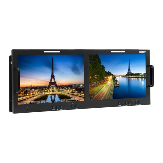
CHAPTER 1: Installation Introduction Overview This 4RU rack-mounted RM-4210WS Series monitor sets a new standard in LCD monitors for broadcast and professional video applications. It provides two 10.1”, 1920 x 1200 resolution, 16:9 format, anti-glare IPS LCD screens. All video formats are scaled to fit on screen in the highest quality using fully digital processing, precision scaling and gamma correction to produce the best images possible. -
Page 6: Safety Symbols
Important: By design, this monitor will only plug into a three-prong outlet for your safety. If the plug does not fit into the outlet, contact an electrician to replace the obsolete outlet. 7. Protect the power cord from being walked on or pinched, particularly at plug connection on the equipment and at the socket. -
Page 7: Sympathetic Vibration
proximity to the unit if this temperature is not exceeded. Otherwise, allow a 1RU (1.75”/44.45mm) space above and below the unit for air circulation. Important To reduce noise, the monitor does not have any fans. As a result, the heat generated by the audio amplifiers, power supplies, and other components is vented by slots in the back of the unit. -
Page 8: Ices-003
instruction manual, may cause harmful interference to radio communications. Operation of this equipment in a residential area is likely to cause harmful interference, in which case the user will be required to correct the interference at their own expense. ICES-003 This Class A digital apparatus complies with Canadian ICES-003. -
Page 9: Chapter 2: Local Operation
CHAPTER 2: Local Operation The RM-4210WS-3G2 models front and rear panels are described in this chapter. Front Panel Figure 2–1: Front Panel Layout 1. Tally Lights: These tri-color (red/green/amber) lights are controlled through a RJ45 connector on the rear panel. For more information about the RJ45 connector, refer to Figure 2-5 and Table 2-1. -
Page 10: On-Screen Display Features
stereo headphones from this mini-stereo connector. Control the volume of the headphones using the Volume setting in the Quick Menu. Refer to the Using the Quick Menu and the OSD Menus section later in this chapter. 5. Power: Each of the two Power buttons turn the associated LCD screen on and off;... - Page 11 Closed Captions from CVBS Line 21 (CEA-608) can be decoded and text is displayed across the screen bottom. The ‘CC’ logo at screen top center indicates captions are present in the SDI stream. The de-embedded Timecode from the HD/SD-SDI source displays on the lower part of the screen.
-
Page 12: Rear Panel
Use of another power adapter provided by the user may negate the compliance or not perform properly. Wohler Technologies cannot accept any responsibility for the outcome in such cases. 1. SDI In 1: This input connector accepts 3G/HD/SD-SDI video signals. It is compliant with SMPTE 424M, SMPTE 259M, SMPTE292M/ITU-R BT601. - Page 13 be viewed using the SDI1 selection on the IN button menu. 2. SDI Out 1: This connector provides a re-shaped and re-clocked duplicate of the SDI In 1 signal. This connection is compliant with SMPTE 424M, SMPTE 259M, SMPTE292M/ITU-R BT601. 3.
-
Page 14: Rear Panel Connectors
Rear Panel Connectors The following figure and tables detail the connections of the Tally and RS-485 connectors on the rear panel. The tables are also silkscreened on the rear panel of the unit for your convenience. Table 2-1: Tally Input Connections Tally Terminal Name CH1-Red CH1-Green... -
Page 15: Using The Quick Menu And The Osd Menus
Using the Quick Menu and the OSD Menus In the following descriptions, refer to Figure 2-5 for the location of the control buttons. Figure 2-5: Screen Control Buttons Quick Menu The Quick Menu provides quick access to a few commonly used features, as listed in Table 2-3. -
Page 16: Osd Menus
OSD Menus The OSD Menus allow you to adjust a wide variety of control parameters for the monitor. Refer to Table 2-4 through Table 2-14 for typical values and domain ranges. The following is a description of how to use the OSD Menus: 1. - Page 17 Table 2-5: Input Select Menu Structure Input Select Parameters Default Value Domain Range Description SDI1 SDI2 One ON at a Use this setting to LINE1 time, all others select which input will be monitored. LINE2 HDMI NTSC SETUP 0, 7.5 NTSC PHASE -50 - 50 OFF: Normal Video...
- Page 18 Table 2-6: Marker Menu Structure Marker Parameters Default Value Domain Range Description Turn all markers on MARKER ON or OFF or off. If 16:9 aspect ratio: OFF (close area marker), 4:3, 13:9, 14:9, 15:9, Set area marker size 16:9, 1.85:1, 2.35:1 AREA MARKER OFF according to the aspect ratio.
- Page 19 Table 2-7: Audio Menu Structure Audio Parameters Default Value Domain Range Description Analog: AUDIO1, AUDIO2 Select the audio source among the AUDIO SOURCE SDI: EBD available signals.* UNDEF (none) Select channel for SPEAK OUT L EBD CH1 EBD CH1-CH16 the left speaker. Select channel for SPEAK OUT R EBD CH2...
- Page 20 Table 2-8: Display Menu Structure Display Parameters Default Value Domain Range Description Turn status display off, on, or automatic. If STATUS DISPLAY AUTO OFF, ON, AUTO automatic, it will display for 15 seconds after each change. Turn AFD display on only AFD DISPLAY ON, OFF when status display is set...
- Page 21 Table 2-9: Line Wave Number vs. Input Signal Input Signal Default Value Domain Range 576i50 23 - 623 480i60 22 - 524 720p 26 - 745 1080i50 1080i60/59.94 21 - 1123 1080sf23/23.97 1035i60 41 - 1120 1080p 42 - 1121 Table 2-10: Closed Caption Menu Structure Closed Caption Parameters...
- Page 22 Table 2-11: Config Menu Structure Config Parameters Default Value Domain Range Description Enable or disable FAST MODE ON or OFF fast mode. Enable or disable FILM MODE DETECT OFF ON or OFF film mode detection. Select Picture by Picture (PbP) or SUB IN TYPE PBP or PIP Picture in Picture...
- Page 23 Table 2-12: Color Temp Menu Structure Color Temp Parameters Default Value Domain Range Description D32, D50, D56, D65, Set the color COLOR TEMP D93, USER1, USER2 temperature. RED GAIN Set the gain for GREEN GAIN 0 to 256 each color. BLUE GAIN RED BIAS Set the offset for...
- Page 24 Table 2-14: IMD Menu Structure IMD Menu Parameters Default Value Domain Range Description Set whether to IMD DISPLAY ON or OFF enable the IMD. Set the color of RED, GREEN, YELLOW, IMD COLOR the IMD WHITE characters. (Up to 16 characters of RM-3270WS- Set the IMD IMD CHARACTER...
-
Page 25: Chapter 3: Technical Info
CHAPTER 3: Technical Info Table 3–1: Specifications Specification Values/Domains Power requirements 100 V to 240 VAC ± 10%, 50/60Hz Power consumption 35 Watts 6.9” x 19” x 1.7” Dimensions; inches H x W x D (mm) (176mm x 484mm x 43mm) Weight 5 lbs. - Page 26 Figure 3–1: RM-4210WS-3G2 Block Diagram Page...
-
Page 27: Supported Video Formats
Supported Video Formats The RM-4210WS-3G2 will display the video formats listed in Table 3-2. Table 3-2: Video Formats Format Video HDMI NTSC 480i60/59.94 576i50 480p60/59.94 576p50 720p24/23.97 720p25 720p30/29.97 720p50 720p60/59.94 1080sf24.23.97 1035i60/59.94 1080i50 1080i60/59.94 1080p24/23.97 1080p25 1080p30/29.97 1080p50 1080p60/59.94 VGA (640X480) SVGA (800X600) XGA (1024X768) -
Page 28: Chapter 4: Using Network Control
CHAPTER 4: Using Network Control The RM-4210WS Web GUI allows you to customize the monitor configuration to perfectly suit your needs. The following setup steps are not necessary if you intend to use the RM-4210WS in its default configuration or if you only make configuration changes using the OSD menus. -
Page 29: Status Page
Figure 4–1: Host IP Settings After making an IP address change such as this, close the control panel and reboot the host computer to be sure the change takes effect. Make the final address, mask and gateway changes in the RM-4210WS System page. - Page 30 Figure 4–2: Status Page IP Address RM-4210WS-3G2 XXXXXXXXXXXX Page...
-
Page 31: Adjust Page
Adjust Page icon following a parameter name indicates that the parameter is only local for the currently selected monitor screen. Otherwise, the parameter is global and the setting applies to both screens. Click the SET button to change a parameter value. Figure 4–3: Adjust Page Page... -
Page 32: Video Display Page
Video Display Page Figure 4–4: Video Display Page Input Setup Page Figure 4–5: Input Setup Page Page... -
Page 33: Marker Page
Marker Page The MARKER OFF/ON setting enables or disables the visibility of all markers on the screen. The settings of each marker are retained as the last change made from either the OSD Menu or this Network Control Page. Figure 4–6: Marker Page Page... -
Page 34: Audio Page
Audio Page First select the AUDIO SOURCE. Then select SPEAK(er) OUT selections for LEFT and RIGHT channels. These also apply to headphone and AUDIO OUT outputs. METER SELECT controls which and how many channels are metered, independently of the SPEAK(er) OUT selections. icon following a parameter name indicates that the parameter is only local for the current selected monitor. -
Page 35: Close Caption Page
Close Caption Page Figure 4–8: Close Caption Page Config Page icon following a parameter name indicates that the parameter is only local for the current selected monitor. Otherwise, the parameter is global and the setting applies to both screens. Figure 4–9: Config Page Page... -
Page 36: Color Temperature Page
Color Temperature Page As with the OSD Color Temp Menu, COPY FROM specifies a USER profile is to be made from it. The USER color profile can be modified as desired from within the OSD Menu. In Figure 4-10, Color Space has been expanded to show the choices available. Figure 4–10: Color Temperature Page Page... -
Page 37: Function Key Page
Function Key Page In Figure 4-11, F2 is shown expanded to see choices available for either function key’s assignment. Some functions, such as FREEZE, can only be initiated by a function key if there is no menu setting for enabling the function. Figure 4–11: Function Key Page Page... -
Page 38: Imd Page
IMD Page There are two ways to enter static IMD character strings, via the network with this page, or with the OSD IMD Menu. Both are retained in the monitor’s memory, and IMD PROTOCOL settings of LOCAL vs. NETWORK decides which one is displayed. In Figure 4-12, Tally Source has been expanded to show the available choices. -
Page 39: System Page
IP ADDRESS, and the last number is usually 1. The LOCK NUMBER is only needed in certain software installation situations. Do not change it unless instructed by Wohler Customer Service. Version numbers are additional information that may be useful when consulting with Wohler Customer Service.
Need help?
Do you have a question about the RM-4210WS Series and is the answer not in the manual?
Questions and answers