
Related Manuals for Wohler RM-2443WS-3G2


Summary of Contents for Wohler RM-2443WS-3G2
-
Page 1: User Guide
RM-2443WS Series • RM-2443WS-3G • RM-2443WS-3G2 2RU, 4-Screen, 4.3” Audio/Video Monitors User Guide User Guide Part Number 821813, Revision A... - Page 2 In no event will Wohler Technologies, Inc. be liable for direct, indirect, special, incidental, or consequential damages resulting from any defect in the hardware, software, or its documentation, even if advised of the possibility of such damages.
-
Page 3: Table Of Contents
TABLE OF CONTENTS Contents User Guide ..................1 TABLE OF CONTENTS ................3 Contents ....................... 3 CHAPTER 1: Installation ............... 5 Introduction ....................5 Overview .................... 5 Features ..................... 5 Safety ......................5 Instructions ..................5 Safety Symbols ..................6 Mounting ..................... - Page 4 Close Caption Page ..................33 Config Page ....................33 Color Temperature Page ................34 Function Key Page ..................35 IMD Page ....................36 System Page ....................37 Page 4...
-
Page 5: Chapter 1: Installation
Features The RM-2443WS-3G2 and -3G audio/video monitors are designed for confidence monitoring of 3G/HD/SD-SDI digital video and CVBS composite analog video. Input signals are easily selected and displayed. Two to sixteen audio channels per screen may be selected for visual monitoring on bar graph style level meters. -
Page 6: Safety Symbols
Important: By design, this monitor will only plug into a three-prong outlet for your safety. If the plug does not fit into the outlet, contact an electrician to replace the obsolete outlet. 7. Protect the power cord from being walked on or pinched, particularly at plug connection on the equipment and at the socket. -
Page 7: Sympathetic Vibration
proximity to the unit if this temperature is not exceeded. Otherwise, allow a 1RU (1.75”/44.45mm) space above and below the unit for air circulation. Important: These monitors contain a fan to ventilate the heat generated by the audio amplifiers, video processing circuitry, and other components. -
Page 8: Ices-003
radiate radio frequency energy and, if not installed and used in accordance with the instruction manual, may cause harmful interference to radio communications. Operation of this equipment in a residential area is likely to cause harmful interference, in which case the user will be required to correct the interference at their own expense. -
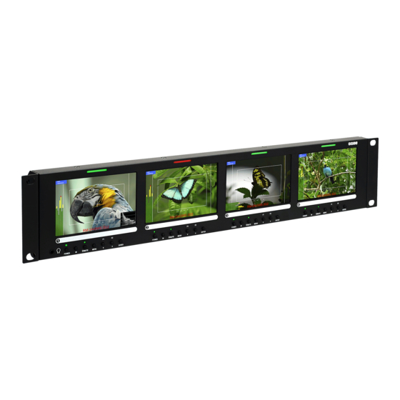
Page 9: Chapter 2: Local Operation
CHAPTER 2: Local Operation The RM-2443WS-3G2 and RM-2443WS-3G front and rear panels are described in this chapter. Front Panel Figure 2–1: Front Panel Layout LCD Screen 1 LCD Screen 2 LCD Screen 3 LCD Screen 4 Tally Light Tally Light... -
Page 10: On-Screen Display Features
Refer to the Quick Menu section of this chapter. 8. In: On the RM-2443WS-3G2, this button switches between the IN1 and IN2. Pressing the IN button will display a list of the possible inputs. It should then be pressed repeatedly to select the required input. - Page 11 Audio Level Meters Waveform / Vectorscope Timecode --: --: --: -- RM-2443WS-3G2 Headphone Jack 1. Input Status: Displays the selected input and video parameters of vertical active line count, (i)nterlaced or (p)rogressive, and field/frame rate in Hz. 2. Area Marker: Used to mark an alternate aspect ratio area of the image. You can set whether to display it, the display brightness, and the matte mode in the Marker Menu.
-
Page 12: Rear Panel
Use of another power adapter provided by the user may negate the compliance or not perform properly. Wohler Technologies cannot accept any responsibility for the outcome in such cases. 1. RM-2443WS-3G2: a) In 1: This input connector accepts 3G/HD/SD-SDI video signals. -
Page 13: Rear Panel Connectors
This BNC jack also accepts a CVBS signal and automatically detects it. b) SDI Out: This connector provides a re-shaped and re-clocked duplicate of the SDI In 1 signal. This connection is compliant with SMPTE 424M, SMPTE 259M, SMPTE292M/ITU-R BT601. It is not an output when a CVBS signal is connected to In. -
Page 14: Using The Quick Menu And The Osd Menus
To light a Tally in red, connect pin 1 (2, 3, or 4) to ground. To light a Tally in green, connect pin 6 (7, 8, or 9) to ground. To light a tally in amber, connect both pins 1 and 6 (2 and 7, 3 and 8, or 4 and 9) to ground. -
Page 15: Quick Menu
Figure 2-6: Screen Control Buttons Quick Menu The Quick Menu provides quick access to a few commonly used features, as listed in Table 2-3. The Quick Menu appears as shown in Figure 2-7. Figure 2-7: Quick Menu - Volume Setting The following is a description of how to use the Quick Menu: 1. -
Page 16: Osd Menus
Menu system. Use the instructions in the previous section to navigate the menus. Table 2-4: Status Menu Structure Status Parameters Default Value Domain Range Description SDI1 INPUT SDI2 (RM-2443WS-3G2 only) FORMAT NO SIGNAL COLOR TEMP D32, D93, D65, D56, D50 Display only for SCAN MODE NORMAL NORMAL, OVER, UNDER... - Page 17 Table 2-6: Marker Menu Structure Marker Parameters Default Value Domain Range Description Turn all markers on MARKER ON or OFF or off. If 16:9 aspect ratio: OFF, 4:3, 15:9, 14:9, Set area marker size 13:9, 1.85:1, 2.35:1 AREA MARKER OFF according to the aspect ratio.
- Page 18 Table 2-7: Audio Menu Structure Audio Parameters Default Value Domain Range Description Select the left SPEAK OUT L EBD CH1 EBD CH1-CH16 headphone channel source. Select the right SPEAK OUT R EBD CH2 EBD CH1-CH16 headphone channel source. Set whether to AUDIO METER ON or OFF display the audio...
- Page 19 Table 2-8: Display Menu Structure Display Parameters Default Value Domain Range Description Turn status display off, on, or automatic. If STATUS DISPLAY AUTO OFF, ON, AUTO automatic, it will display for 15 seconds after each change. Turn AFD display on only AFD DISPLAY ON, OFF when status display is set...
- Page 20 Table 2-10: Closed Caption Menu Structure Closed Caption Parameters Default Value Domain Range Description Set type of CVBS CLOSED CAPTION caption to display, TEXT1 or turn it off. TEXT2 TEXT3 TEXT4 Set whether to SDI CC LOG (‘CC’ Logo) ON or OFF display SDI closed caption information Table 2-11: Config Menu Structure...
- Page 21 correct the situation. ** Note: Setting the Fan to AUTO or ON can prolong the life of the product. Table 2-12: Color Temp Menu Structure Color Temp Parameters Default Value Domain Range Description D32, D50, D56, D65, Set the color COLOR TEMP D93, USER1, USER2 temperature.
- Page 22 Table 2-14: IMD Menu Structure IMD Menu Parameters Default Value Domain Range Description Set whether to IMD DISPLAY ON or OFF enable the IMD. Set the color of RED, GREEN, YELLOW, IMD COLOR the IMD WHITE characters. (Up to 16 characters of RM-2443WS- Set the IMD IMD CHARACTER...
-
Page 23: Chapter 3: Technical Info
4 x 3G/HD/SD-SDI or SD-SDI: SMPTE 259M, ITU-R BT.656 CVBS (RM-2443WS-3G) HD-SDI: SMPTE 292M/274M/296M 8 x 3G/HD/SD-SDI or 3G-SDI: SMPTE 425-Level A CVBS (RM-2443WS-3G2) Video Input Impedance SDI and CVBS: 75Ω 4 x 3G/HD/SD-SDI on BNC (RM-2443WS- Video Outputs 3G2 only) Headphones Stereo;... - Page 24 Figure 3–1: RM-2443WS-3G Block Diagram Page...
- Page 25 Figure 3–2: RM-2443WS-3G2 Block Diagram Page...
-
Page 26: Chapter 4: Using Network Control
CHAPTER 4: Using Network Control The RM-2443WS Web GUI allows you to customize the monitor configuration to perfectly suit your needs. The following setup steps are not necessary if you intend to use the RM-2443WS in its default configuration or if you only make configuration changes using the OSD Menus. -
Page 27: Status Page
Figure 4–1: Host IP Settings After making an IP address change such as this, close the control panel and reboot the host computer to be sure the change takes effect. Make the final address, mask and gateway changes in the RM-2443WS System setup page. - Page 28 Figure 4–2: Status Page Page...
-
Page 29: Adjust Page
Adjust Page icon following a parameter name indicates that the parameter is only local for the currently selected monitor screen. Otherwise, the parameter is global and the setting applies to both screens. Click the SET button to change a parameter value. Figure 4–3: Adjust Page Page... -
Page 30: Video Display Page
Video Display Page Figure 4–4: Video Display Page Input Setup Page Figure 4–5: Input Setup Page Page... -
Page 31: Marker Page
Marker Page The MARKER OFF/ON setting enables or disables the visibility of all markers on the screen. The settings of each marker are retained as the last change made from either the OSD Menu or this Network Control Page. Figure 4–6: Marker Page Page... -
Page 32: Audio Page
Audio Page First select the AUDIO SOURCE. Then select SPEAK OUT selections for LEFT and RIGHT channels. These apply to the headphone jack output. METER SELECT controls which and how many channels are metered, independently of the SPEAK OUT selections. icon following a parameter name indicates that the parameter is only local for the current selected monitor. -
Page 33: Close Caption Page
Close Caption Page Figure 4–8: Close Caption Page Config Page icon following a parameter name indicates that the parameter is only local for the current selected monitor. Otherwise, the parameter is global and the setting applies to both screens. Figure 4–9: Config Page Page... -
Page 34: Color Temperature Page
Color Temperature Page As with the OSD Color Temp Menu, COPY FROM specifies a USER profile is to be made from it. The USER color profile can be modified as desired from within the OSD Menu. In Figure 4-10, Color Space has been expanded to show the choices available. Figure 4–10: Color Temperature Page Page... -
Page 35: Function Key Page
Function Key Page In Figure 4-11, F2 is shown expanded to see choices available for either function key’s assignment. Some functions, such as FREEZE, can only be initiated by a function key if there is no menu setting for enabling the function. Figure 4–11: Function Key Page Page... -
Page 36: Imd Page
IMD Page There are two ways to enter static IMD character strings, via the network with this page, or with the OSD IMD Menu. Both are retained in the monitor’s memory, and IMD PROTOCOL settings of LOCAL vs. NETWORK decides which one is displayed. In Figure 4-12, Tally Source has been expanded to show the available choices. -
Page 37: System Page
IP ADDRESS, and the last number is usually 1. The LOCK NUMBER is only needed in certain software installation situations. Do not change it unless instructed by Wohler Customer Service. Version numbers are additional information that may be useful when consulting with Wohler Customer Service.
Need help?
Do you have a question about the RM-2443WS-3G2 and is the answer not in the manual?
Questions and answers