
Related Manuals for Wohler RM-4210W-3G2


Summary of Contents for Wohler RM-4210W-3G2
-
Page 1: User Guide
RM-4210W-3G2 4RU, 2-Screen, 10.1” Dual 3G/HD/SD-SDI Input Audio/Video Monitor User Guide Part Number 821826, Revision C... - Page 2 In no event will Wohler Technologies, Inc. be liable for direct, indirect, special, incidental, or consequential damages resulting from any defect in the hardware, software, or its documentation, even if advised of the possibility of such damages.
-
Page 3: Table Of Contents
TABLE OF CONTENTS Contents User Guide ..................1 TABLE OF CONTENTS................3 Contents ......................3 CHAPTER 1: Installation ................4 Introduction ....................4 Overview....................4 Features ....................4 Safety......................4 Instructions ...................4 Safety Symbols..................5 Mounting....................5 Heat Dissipation..................5 Sympathetic Vibration................6 Mechanical Bracing .................6 Electrical Interference ................6 Power ....................6 Compliance .....................6 FCC ......................6 ICES-003 ....................7 CHAPTER 2: Local Operation ..............8... -
Page 4: Chapter 1: Installation
CHAPTER 1: Installation Introduction Overview This 4RU rack-mounted RM-4210W-3G2 monitor sets a new standard in LCD monitors for broadcast and professional video applications. It provides two 10.1”, 1920 x 1200 resolution, 16:10 format, anti-glare IPS LCD screens. All video formats are scaled to fit on screen in the highest quality using fully digital processing, precision scaling and gamma correction to produce the best images possible. -
Page 5: Safety Symbols
Important: By design, this monitor will only plug into a three-prong outlet for your safety. If the plug does not fit into the outlet, contact an electrician to replace the obsolete outlet. 7. Protect the power cord from being walked on or pinched, particularly at plug connection on the equipment and at the socket. -
Page 6: Sympathetic Vibration
Celsius (104° Fahrenheit). Adjacent devices can be rack mounted (or stacked) in proximity to the unit if this temperature is not exceeded. Otherwise, allow a 1RU (1.75”/44.45mm) space above and below the unit for air circulation. Important To reduce noise, the monitor does not have any fans. As a result, the heat generated by the audio amplifiers, power supplies, and other components is vented by slots in the back of the unit. -
Page 7: Ices-003
operated in a commercial environment. This equipment generates, uses, and can radiate radio frequency energy and, if not installed and used in accordance with the instruction manual, may cause harmful interference to radio communications. Operation of this equipment in a residential area is likely to cause harmful interference, in which case the user will be required to correct the interference at their own expense. -
Page 8: Chapter 2: Local Operation
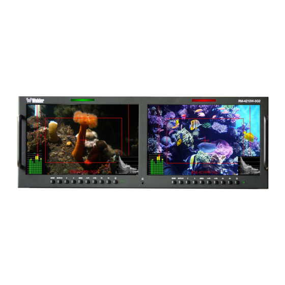
CHAPTER 2: Local Operation The dual video input RM-4210W-3G2 front and rear panels are described in this chapter. Front Panel Figure 2–1: Front Panel Layout LCD Screen 1 LCD Screen 2 Tally Light Tally Light gpxx gpxx RM-4210W-3G2 RM-4210W-3G2 Mode... -
Page 9: On-Screen Display Features
6. Mute: The Mute/Audio Select button picks the audio source to be from the left or right screen program. When audio has already been selected on a screen, this button becomes a Mute control, enabling or disabling audio in the speakers and headphones. - Page 10 Figure 2-2: Display Features 1. Input Status: Displays the selected input and video parameters of vertical active line count, (i)nterlaced or (p)rogressive, and field/frame rate in Hz. This display may be active for a few seconds after a source is selected, or it can be displayed all of the time.
-
Page 11: Rear Panel
Use of another power adapter provided by the user may negate the compliance or not perform properly. Wohler Technologies cannot accept any responsibility for the outcome in such cases. 1. 3G-SDI In 1: This input connector accepts 3G/HD/SD-SDI video signals. It is compliant with SMPTE 424M, SMPTE 259M, SMPTE292M/ITU-R BT601. - Page 12 5. CVBS In: This is the input for an analog CVBS video signal. It can be viewed making the AV selection with the Mode button. 6. CVBS Out: The CVBS video signal is repeated on this output. 7. HDMI In: An HDMI input is provided. It uses an HDMI Type-A connector. It can be viewed using the HDMI selection on the IN button menu.
-
Page 13: Rear Panel Connectors
Rear Panel Connectors The following figure and tables detail the connections of the Tally and RS-485 connectors on the rear panel. The tables are also silkscreened on the rear panel of the unit for your convenience. Table 2-1: Tally Connections Tally Terminal Name CH1-R CH2-R... -
Page 14: Using The Volume Control And The Osd Menus
Using the Volume Control and the OSD Menus In the following descriptions, refer to Figure 2-5 for the location of the control buttons. Figure 2-5: Screen Control Buttons Volume Control The volume of the speakers and headphones can be quickly accessed by pressing either the Left (<) or Right (>) buttons shown in Figure 2-5. -
Page 15: Osd Menus
OSD Menus The OSD Menus allow you to adjust a wide variety of control parameters for the monitor. Refer to Table 2-3 through Table 2-9 for typical values and domain ranges. The following is a description of how to use the OSD Menus: 1. - Page 16 Table 2-4: Audio Menu Structure Audio Parameters Default Value Domain Range Description Select the AUDIO METERS SOLID appearance of the TRANSParent audio meters. Select the meter PR1, GP1, GP2, GP3, source and which AUDIO DISPLAY GP4, GP1-2, GP1-4 channels to display.
- Page 17 CENTER Turn center marker OFF, ON MARKER display on or off. Set safety marker SAFE ZONE OFF, 80%, 85%, 90%, size according to the MARKER 93%, 96% aspect ratio and scan mode. OFF, 4:3, 13:9, 14:9, RATIO 15:9, 16:9, 1.85:1, Set area marker size.
- Page 18 Table 2-7: Tools Menu Structure Tools Parameters Default Value Domain Range Description BLUE SCREEN REC SCREEN Set the screen color NO SIGNAL BLUE SCREEN GREEN SCREEN displayed when there BLACK SCREEN is no video signal. WHITE SCREEN MONO Enable or disable the CHECK FIELD display of check GREEN...
- Page 19 RM-4210W- MODIFY IMD 0 - 16 CHARACTERS * Enter local IMD text. GREEN Set the color of the COLOR IMD ORANGE IMD text. BLACK WHITE BACKGROUND Add a colored box BLACK GREEN behind the IMD text. ORANGE BLACK * To enter the characters for the MODIFY IMD setting, navigate to the setting and press Right.
- Page 20 Table 2-8: Settings Menu Structure Settings Parameters Default Value Domain Range Description ENGLISH CHINESE SPANISH Select the PORTUGUESE language that is LANGUAGE ENGLISH FRENCH used in the OSD DUTCH Menus. GERMAN JAPANESE Adjust the OSD TRANS. transparency of MIDDLE the OSD Menus. HIGH Adjust the MENU H POS...
-
Page 21: Usb Upgrade
If it should become necessary to upgrade the software of the RM-4210W-3G, this can easily be done without any additional equipment. Use the following steps: 1. Obtain the upgrade file from Wohler Technologies and copy it to a mini USB flash drive. -
Page 22: Chapter 3: Technical Info
CHAPTER 3: Technical Info Table 3–1: Specifications Specification Values/Domains Power requirements 100 V to 240 VAC ± 10%, 50/60Hz Power consumption 35 Watts 6.9” x 19” x 1.7” Dimensions; inches H x W x D (mm) (176mm x 484mm x 43mm) Weight 5.9 lbs. - Page 23 Figure 3–1: RM-4210W-3G2 Block Diagram Tally Light 1 Tally Tally Interface RS-485 In / Out LCD 1 Ethernet 10.1" 16:10 With 16-Channel Audio Meters Screen 1 I/O 3G/HD/SD-SDI 1 In Input Conv 3G/HD/SD-SDI 1 Out Select Power / 3G/HD/SD-SDI 2 In...
-
Page 24: Supported Video Formats
Supported Video Formats The RM-4210W-3G2 will display the video formats listed in Table 3-2. Table 3–2: Video Format Support Input Video Formats Supported 480i/576i 720p(60/59.94/50/30/29/25/24/23.98) 1080i(60/59.94/50) 1080p(60/59.94/50/30/29.97/25/24/24sF/23.98/23.98sF) 480i/576i/480p/576p 1080i (60/59.94/50) HDMI 720p (60/59.94/50/30/29/25/24/23.98) 1080p(60/59.94/50/30/29.97/25/24/24sF/23.98/23.98sF) Page... -
Page 25: Chapter 4: Using Network Control
Connect both the PC and the RM-4210W-3G to a DHCP server on the same network, and then run the PC Control software on the PC. Log in using the screen that appears, as shown in Figure 4-1. The default Username is wohler and the default Password is 1. - Page 26 Figure 4–2: Control Interface Click the Add Monitors button. The Monitor Control screen appears, as shown in Figure 4-3: Page...
- Page 27 Figure 4–3: Monitor Control - IP Address At this point, the RM-4210W-3G should have already set its IP address and it will be visible in the upper left of its screens. Type this address into the IP location on the Monitor Control screen in the PC.
- Page 28 Figure 4–4: Video Display Page When you are connected to the desired screen on the RM-4210W-3G, the Connection Status will show the IP address that is connected. Refer to Figure 4-5: Figure 4-5 - Connection Status Page...
-
Page 29: Control Tab
The RM-4210W-3G control and options are listed on the Control, Function 1, Function 2, and UMD tabs that appear on this screen. The following three sections of this manual show each of these four tabs. The screens are self-explanatory and simple to operate. -
Page 30: Function 1 Tab
Function 1 Tab Click on the Function 1 tab to configure the options of the chosen screen. This tab is shown in Figure 4-7: Figure 4–7: Function 1 Tab Function 1 Tab Note: The tab shown is representative and the actual tab may differ somewhat. Page... -
Page 31: Function 2 Tab
Function 2 Tab Click on the Function 2 tab to configure the options of the chosen screen. This tab is shown in Figure 4-8: Figure 4–8: Function 2 Tab Note: The tab shown is representative and the actual tab may differ somewhat. Page... -
Page 32: Umd Tab
UMD Tab Click on the UMD tab to configure the options of the chosen screen. This tab is shown in Figure 4-9: Figure 4–9: UMD Tab UMD Tab Note: The tab shown is representative and the actual tab may differ somewhat. When you are finished setting up the chosen screen, you may use the Monitor pull down selection to switch to another RM-4210W-3G screen for setup or simply close the PC Control program.
Need help?
Do you have a question about the RM-4210W-3G2 and is the answer not in the manual?
Questions and answers