
Related Manuals for Wohler RM-3270WS-3G


Summary of Contents for Wohler RM-3270WS-3G
-
Page 1: User Guide
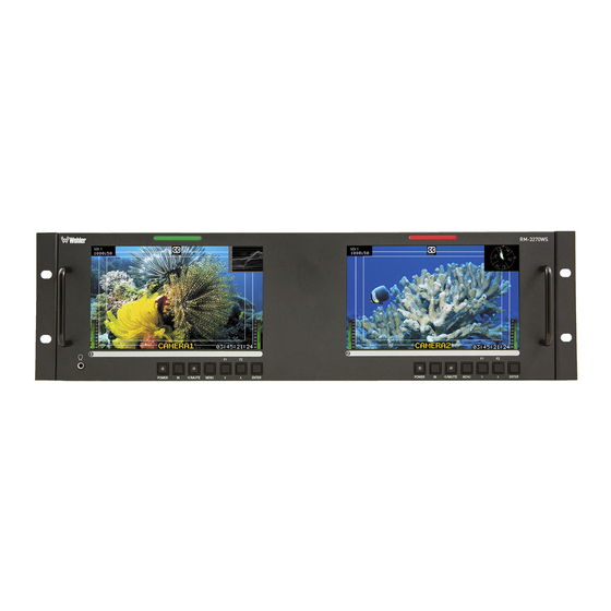
RM-3270WS Series • RM-3270WS-3G • RM-3270WS-3G2 3RU, 2-Screen, 7” Audio/Video Monitors User Guide User Guide Part Number 821805, Revision B... - Page 2 In no event will Wohler Technologies, Inc. be liable for direct, indirect, special, incidental, or consequential damages resulting from any defect in the hardware, software, or its documentation, even if advised of the possibility of such damages.
-
Page 3: Table Of Contents
TABLE OF CONTENTS Contents User Guide ..................1 TABLE OF CONTENTS ................3 Contents ......................3 CHAPTER 1: Installation ................ 5 Introduction ....................5 Overview....................5 Features ....................5 Safety ......................5 Instructions ................... 5 Safety Symbols ..................6 Mounting ....................6 Heat Dissipation .................. - Page 4 Close Caption Page ..................34 Config Page ....................34 Color Temperature Page .................. 35 Function Key Page ..................36 IMD Page ...................... 37 System Page ....................38 Page 4...
-
Page 5: Chapter 1: Installation
CHAPTER 1: Installation Introduction Overview The 3RU rack-mounted RM-3270WS-3G Series monitors set a new standard in LCD monitors for broadcast and professional video applications. It provides two 7”, 1024 x 600 resolution, 15:9 format, anti-glare IPS LCD screens. All video formats are scaled to fit on screen in the highest quality using full, digital processing, precision scaling and gamma correction to produce the best images possible. -
Page 6: Safety Symbols
7. Protect the power cord from being walked on or pinched, particularly at plug connection on the equipment and at the socket. 8. Use only the attachments/accessories specified by the manufacturer. 9. Unplug the equipment during lightning storms or when unused for long periods of time. -
Page 7: Sympathetic Vibration
Important To reduce noise, the monitor does not have any fans. As a result, the heat generated by the audio amplifiers, power supplies, and other components is vented by slots in the back of the unit. Therefore, as a safety precaution, you must allow proper ventilation on these surfaces. -
Page 8: Ices-003
their own expense. ICES-003 This Class A digital apparatus complies with Canadian ICES-003. Cet appareil numérique de la classe A est conforme à la norme NMB-003 du Canada. Page 8... -
Page 9: Chapter 2: Local Operation
CHAPTER 2: Local Operation Single video input RM-3270WS-3G and dual video input RM-3270WS-3G2 models share a common hardware layout for front and rear panels as described in this chapter. Front Panel Figure 2–1: Front Panel Layout 1. Tally Lights: These tri-color (red/green/amber) lights are controlled through a RJ45 connector on the rear panel. -
Page 10: On-Screen Display Features
off; the LED glows green to indicate on. When the indicator above the power switch is green then the unit is receiving power. When the indicator is flashing, the unit is in stand-by mode. 6. Mute: The Mute button enables or disables the audio to the speakers or the headphones. - Page 11 sizes. Closed Captions from CVBS Line 21 (CEA-608) can be decoded and text is displayed across the screen bottom. The ‘CC’ logo at screen top center indicates captions are present in the SDI stream, but those captions will not be displayed as is possible in a CVBS stream.
-
Page 12: Rear Panel
MAIN Menu. 9. AFD/CC: SDI AFD (Active Format Description) and CC (Closed Caption) information will display at the top center of the screen as icons. Rear Panel Figure 2-3: RM-3270WS-3G Rear Panel Layout SDI / SDI / Left Ethernet... - Page 13 2. SDI / CVBS Connector 2: The function of this connector depends upon the model: a) SDI 1 Out: On the RM-3270WS-3G, a re-shaped and re-clocked duplicate of the SDI 1 input signal is generated from this BNC jack. Refer to Figure 2-3. This connection is compliant with SMPTE 424M, SMPTE 259M, SMPTE292M/ITU-R BT601.
-
Page 14: Rear Panel Connectors
7. Ethernet: The 10/100M Ethernet connector is used to connect with a computer to modify the display settings remotely. CAT5 network cables are recommended for medium distances. CAT6 twisted pair shielded cables are recommended for longer distances. 8. RS-485 In/Out: These RJ-45 jacks are used for dynamic Tally/IMD controls. Two jacks are provided for in &... -
Page 15: Using The Quick Menu And The Osd Menus
Table 2-2: RS-485 I/O Connections RS-485 Terminal Name 1, 2 Tx- (pair A) Rx+ (pair B) Rx- (pair B) Tx+ (pair A) 7, 8 Using the Quick Menu and the OSD Menus In the following descriptions, refer to Figure 2-6 for the location of the control buttons. -
Page 16: Osd Menus
Table 2-3: Quick Menu Parameters Default Value Domain Range VOLUME 0 - 16 BRIGHTNESS 0 - 50 0 - 50 CONTRAST CHROMA 0 - 50 OSD Menus The OSD Menus allow you to adjust a wide variety of control parameters for the monitor. -
Page 17: Osd Menus
OSD Menus The following tables describe the information and settings available in the OSD Menu system. Use the instructions in the previous section to navigate the menus. Table 2-4: Status Menu Structure Status Menu Parameters Default Value Domain Range Description Displays the value of the INPUT IN 1, IN2... - Page 18 Table 2-6: Marker Menu Structure Marker Parameters Default Value Domain Range Description Turn all markers on MARKER ON or OFF or off. OFF, 4:3, 13:9, 14:9, Set area marker size. AREA MARKER OFF 15:9, 16:9, 1.85:1, 2.35:1 CENTER Turn center marker ON or OFF MARKER display on or off.
- Page 19 Table 2-7: Audio Menu Structure Audio Parameters Default Value Domain Range Description (Analog) AUDIO1, Select the audio AUDIO SOURCE AUDIO2, (SDI) EBD, source among the UNDEF (none) available signals. Select channel for SPEAK OUT L EBD CH1 EBD CH1-CH16 the left speaker. Select channel for SPEAK OUT R EBD CH2...
- Page 20 Table 2-8: Display Menu Structure Display Parameters Default Value Domain Range Description Turn status display off, on, or automatic. If automatic, it will display STATUS DISPLAY AUTO OFF, ON, AUTO for 15 seconds after each change. Turn AFD display on only when status display is set AFD DISPLAY ON or OFF...
- Page 21 Table 2-10: Config Menu Structure Config Default Parameters Domain Range Description Value Enable or disable FAST MODE ON or OFF fast mode. Enable or disable FILM MODE DETECT ON or OFF film mode detection. Set backlight BACK LIGHT 0 to 30 timeout.
- Page 22 Table 2-12: Function Key Menu Structure Function Key Description Parameters Default Value Domain Range Set up the SCAN, NATIVE, ASPECT, BLUE ONLY, MONO, F1 Function MARKER, H/V DELAY, key action. SCAN AUDIO METER, FAST MODE, TC, IMD, MUTE, CC, FREEZE, UNDEF (none) Set up the SCAN, NATIVE, ASPECT,...
- Page 23 Table 2-13: IMD Menu Structure IMD Menu Parameters Default Value Domain Range Description Set whether to IMD DISPLAY ON or OFF enable the IMD. Set the color of RED, GREEN, YELLOW, IMD COLOR the IMD WHITE characters. RM-3270WS- - (16 characters of text Set the IMD IMD CHARACTER for static LOCAL display)
-
Page 24: Chapter 3: Technical Info
CHAPTER 3: Technical Info Table 3–1: Specifications Specification Values/Domains Power requirements 100 V to 240 VAC ± 10%, 50/60Hz Power consumption 35 Watts 5.2” x 19” x 1.7” Dimensions; inches H x W x D (mm) (132mm x 484mm x 43mm) Weight 3.5 lbs. - Page 25 Figure 3–1: RM-3270WS-3G Block Diagram Page...
- Page 26 Figure 3–2: RM-3270WS-3G2 Block Diagram Page...
-
Page 27: Chapter 4: Using Network Control
CHAPTER 4: Using Network Control The RM-3270WS Web GUI allows you to customize the monitor configuration to perfectly suit your needs. The following setup steps are not necessary if you intend to use the RM-3270WS in its default configuration or if you only make configuration changes using the OSD menus. -
Page 28: Status Page
Figure 4–1: Host IP Settings After making an IP address change such as this, close the control panel and reboot the host computer to be sure the change takes effect. Make the final address, mask and gateway changes in the RM-3270WS System page. - Page 29 Figure 4–2: Status Page IP Address Page...
-
Page 30: Adjust Page
Adjust Page icon following a parameter name indicates that the parameter is only local for the currently selected monitor screen. Otherwise, the parameter is global and the setting applies to both screens. Click the SET button to change a parameter value. Figure 4–3: Adjust Page Page... -
Page 31: Video Display Page
Video Display Page Figure 4–4: Video Display Page Input Setup Page Note that IN2 is only present on the RM-3270WS-3G2, but is not present on the RM-3270WS-3G. Figure 4–5: Input Setup Page Page... -
Page 32: Marker Page
Marker Page The MARKER OFF/ON setting enables or disables the visibility of all markers on the screen. The settings of each marker are retained as the last change made from either the OSD Menu or this Network Control Page. Figure 4–6: Marker Page Page... -
Page 33: Audio Page
Audio Page First select the AUDIO SOURCE. Then select SPEAK(er) OUT selections for LEFT and RIGHT channels. These also apply to headphone and AUDIO OUT outputs. METER SELECT controls which and how many channels are metered, independently of the SPEAK(er) OUT selections. icon following a parameter name indicates that the parameter is only local for the current selected monitor. -
Page 34: Close Caption Page
Close Caption Page Figure 4–8: Close Caption Page Config Page icon following a parameter name indicates that the parameter is only local for the current selected monitor. Otherwise, the parameter is global and the setting applies to both screens. Figure 4–9: Config Page Page... -
Page 35: Color Temperature Page
Color Temperature Page As with the OSD Color Temp Menu, COPY FROM specifies a USER profile is to be made from it. The USER color profile can be modified as desired from within the OSD Menu. In Figure 4-10, Color Space has been expanded to show the choices available. Figure 4–10: Color Temperature Page Page... -
Page 36: Function Key Page
Function Key Page In Figure 4-11, F2 is shown expanded to see choices available for either function key’s assignment. Some functions, such as FREEZE, can only be initiated by a function key if there is no menu setting for enabling the function. Figure 4–11: Function Key Page Page... -
Page 37: Imd Page
IMD Page There are two ways to enter static IMD character strings, via the network with this page, or with the OSD IMD Menu. Both are retained in the monitor’s memory, and IMD PROTOCOL settings of LOCAL vs. NETWORK decides which one is displayed. In Figure 4-12, Tally Source has been expanded to show the available choices. -
Page 38: System Page
IP ADDRESS, and the last number is usually 1. The LOCK NUMBER is only needed in certain software installation situations. Do not change it unless instructed by Wohler Customer Service. Version numbers are additional information that may be useful when consulting with Wohler Customer Service.
Need help?
Do you have a question about the RM-3270WS-3G and is the answer not in the manual?
Questions and answers