Advertisement
Quick Links
LEKF-TF2Z582EN-A
ORIGINAL INSTRUCTIONS
Instruction Manual
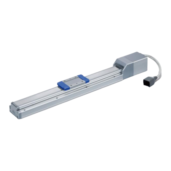
Electric Actuator / Slider type
Series LEKFS**G
Motor: Step motor (servo 24 VDC)
High Performance Battery-less absolute encoder
The intended use of this Electrical Actuator is to convert an electrical
input signal into mechanical motion.
1 Safety Instructions
These safety instructions are intended to prevent hazardous situations
and/or equipment damage. These instructions indicate the level of
potential hazard with the labels of "Caution," "Warning" or "Danger."
They are all important notes for safety and must be followed in addition
*1)
to International Standards (ISO/IEC)
, and other safety regulations.
*1)
ISO 4414: Pneumatic fluid power - General rules relating to systems.
ISO 4413: Hydraulic fluid power - General rules relating to systems.
IEC 60204-1: Safety of machinery - Electrical equipment of machines.
(Part 1: General requirements)
ISO 10218-1: Manipulating industrial robots -Safety. etc.
• Refer to the product catalogue, Operation Manual and Handling
Precautions for SMC Products for additional information.
• Keep this manual in a safe place for future reference.
Caution indicates a hazard with a low level of risk which, if
Caution
not avoided, could result in minor or moderate injury.
Warning indicates a hazard with a medium level of risk
Warning
which, if not avoided, could result in death or serious injury.
Danger indicates a hazard with a high level of risk which, if
Danger
not avoided, will result in death or serious injury.
Warning
• Always ensure compliance with relevant safety laws and standards.
All work must be carried out in a safe manner by a qualified person in
compliance with applicable national regulations.
• Special products (-X#, -D#) might have specifications different from
those shown in the specifications section. Contact SMC for specific
drawings.
2 Specifications
LEKFS25 series
Model
LEKFS25
Stroke [mm]
50 to 800
Horizontal
15
28
Max. work load
Note 2)
[kg]
Vertical
3
7.5
Up to 400 stroke
20 to 1500 12 to 750
401 to 500
20 to 1100 12 to 750
Speed
501 to 600
20 to 900
12 to 540
[mm/s]
601 to 700
20 to 630
12 to 420
701 to 800
20 to 550
12 to 330
10000
Max. acceleration / deceleration
[mm/s
2
]
5000
Positioning repeatability [mm]
±0.01 (lead H: ±0.02)
Lost motion [mm]
Note 3)
0.05 or less
Screw Lead [mm]
20
12
2
Note 4)
Impact/Vibration resistance [m/s
]
50 / 20
Actuation method
Ball screw (LEKFS*)
Ball screw + Belt (LEKFS*R/L)
Guide type
Linear guide
Operating temperature [℃]
5 to 40
Operating humidity [%RH]
90 or less (no condensation)
□
Motor size [mm]
42
Motor type
Battery-less absolute
(Step motor 24 VDC)
Encoder
Battery-less absolute
Rated Voltage [V]
24 VDC ±10%
Note 5) 7)
Max. Power consumption [W]
126
Lock Type
Note 6)
Non magnetizing lock
Holding force [N]
47
78
Note 7)
Power consumption [W]
5
Rated voltage [V]
24 VDC ±10%
LEKFS32 series
Model
LEKFS32
Stroke [mm]
50 to 1000
Horizontal
40
50
Max. work load
Note 2)
[kg]
Vertical
4
10
Up to 400 stroke
24 to 1300 16 to 1000
401 to 500
24 to 1300 16 to 950
501 to 600
24 to 1200 16 to 800
Speed [mm/s]
601 to 700
24 to 930
16 to 620
701 to 800
24 to 750
16 to 500
801 to 900
24 to 610
16 to 410
901 to 1000
24 to 500
16 to 340
10000
Max. acceleration / deceleration
2
[mm/s
]
5000
Positioning repeatability [mm]
±0.01 (lead H: ±0.02)
Note 3)
Lost motion [mm]
0.05 or less
Screw Lead [mm]
24
16
Impact/Vibration resistance [m/s
2
]
Note 4)
50 / 20
Actuation method
Ball screw (LEKFS*)
Ball screw + Belt (LEKFS*R/L)
Guide type
Linear guide
Operating temperature [℃]
5 to 40
Operating humidity [%RH]
90 or less (no condensation)
□
Motor size [mm]
56.4
Motor type
Battery-less absolute
(Step motor 24 VDC)
Encoder
Battery-less absolute
Rated Voltage [V]
24 VDC ±10%
Max. Power consumption [W]
Note 5) 7)
222
Note 6)
Lock Type
Non magnetizing lock
Holding force [N]
72
118
Power consumption [W]
Note 7)
5
Rated voltage [V]
24 VDC ±10%
2 Specifications (continued)
LEKFS40 series
Model
Stroke [mm]
40
Horizontal
Max. work load
15
Note 2)
[kg]
Vertical
6 to 500
Up to 400 stroke
30 to 1200 20 to 1000 10 to 500
6 to 400
401 to 500
30 to 1200 20 to 1000 10 to 500
6 to 270
501 to 600
30 to 1200 20 to 1000 10 to 500
6 to 230
601 to 700
30 to 1200 20 to 900
6 to 180
Speed [mm/s]
701 to 800
30 to 1140 20 to 760
801 to 900
30 to 930
901 to 1000
30 to 780
1001 to 1100
30 to 660
6
1101 to 1200
30 to 570
Max. acceleration / deceleration
2
[mm/s
]
Positioning repeatability [mm]
Lost motion [mm]
Note 3)
Screw Lead [mm]
2
Note 4)
Impact/Vibration resistance [m/s
]
Actuation method
Guide type
Operating temperature [℃]
Operating humidity [%RH]
157
LEKFS40 series(continued)
)
Motor size [mm]
Motor type
68
18
Encoder
8 to 500
Rated Voltage [V]
8 to 500
Max. Power consumption [W]
Note 5) 7)
8 to 400
Lock Type
Note 6)
8 to 310
Holding force [N]
8 to 250
Note 7)
Power consumption [W]
8 to 200
Rated voltage [V]
8 to 170
Note 1) Consult with SMC for non-standard strokes as they are produced as
special orders.
2
Note 2) The maximum workload at 3000 m/s
.
Speed varies according to the work load. Check the "Speed–Work Load
Graph" as a Guide in the catalogue on the SMC website
(URL: https://www.smcworld.com).
8
Furthermore, if the cable length exceeds 5 m, then the speed and work
load may decrease by up to 10% for each additional 5 m.
Note 3) A reference value for correcting an error in reciprocal operation.
Note 4) Impact resistance: No malfunction occurred when the actuator was tested
with a drop tester in both an axial and a perpendicular direction to the lead
screw. The test was performed with the actuator in the initialized state.
Vibration resistance: No malfunction occurred in a test ranging between
45 to 2000 Hz. The test was performed in both an axial and a perpendicular
direction to the lead screw. The test was performed with the actuator in the
initialized state.
Note 5) The power consumption including the controller is for when the actuator is
operating.
Note 6) For models with lock only.
Note 7) For an actuator with lock, add the power consumption for the lock.
216
2 Specifications (continued)
Product weight
2.1
Series
LEKFS40
Stroke [mm]
150 to 1200
Product weight [kg]
26
60
75
Lock weight [kg]
4.5
4.5
25
Series
Stroke [mm]
Product weight [kg]
Lock weight [kg]
10 to 440
10 to 350
Series
20 to 620
10 to 280
Stroke [mm]
20 to 520
10 to 250
Product weight [kg]
20 to 440
10 to 220
Lock weight [kg]
20 to 380
10 to 190
Series
10000
Stroke [mm]
5000
Product weight [kg]
±0.01 (lead H: ±0.02)
Lock weight [kg]
0.05 or less
30
20
10
Series
50 / 20
Stroke [mm]
Ball screw (LEKFS*)
Product weight [kg]
Ball screw + Belt (LEKFS*R/L)
Lock weight [kg]
Linear guide
5 to 40
Series
90 or less (no condensation)
Stroke [mm]
Product weight [kg]
Lock weight [kg]
□
3 Installation
56.4
Battery-less absolute
3.1 Installation
(Step motor 24 VDC)
Battery-less absolute
• Do not install the product unless the safety instructions have been read
24 VDC ±10%
and understood.
222
• Do not use the product in excess of its allowable specification.
• When installing, inspecting or performing maintenance on the product,
Non magnetizing lock
be sure to turn off the power supplies. Then, lock it so it cannot be
75
113
245
tampered with while work is happening.
5
• Keep the flatness of the mounting surface to within 0.1 mm maximum.
24 VDC ±10%
Insufficient flatness of a work piece or actuator mounting surface can
cause play in the guide and increased sliding resistance. In the case
of overhang mounting (including cantilever), use a support plate or
support guide to avoid deflection of the actuator body.
• When mounting the actuator, use all mounting holes.
If all mounting holes are not used, this will not maintain the specified
performance. e.g. the amount of displacement of the table will increase.
• When mounting the actuator leave a gap of 40 mm or more to allow
for bending of the actuator cable.
• When mounting the actuator or workpiece, use screws with adequate
length and tighten them with adequate torque.
Tightening the screws with a torque higher than recommended may
cause malfunction, whilst tightening with a torque lower than
recommended can cause displacement of the mounting position, or
dropping of the work piece.
LEKFS25
50
100
150
200
250
300
350
400
1.7
1.8
1.9
2.1
2.3
2.4
2.5
2.6
0.26
LEKFS25
450
500
600
700
800
2.8
2.9
3.2
3.5
3.8
0.26
LEKFS32
50
100
150
200
250
300
350
400
3.6
3.8
4.0
4.2
4.5
4.7
4.9
5.1
0.53
LEKFS32
450
500
600
700
800
900
1000
5.3
5.5
5.9
6.3
6.7
7.1
7.5
0.53
LEKFS40
150
200
250
300
350
400
450
500
5.5
5.8
6.1
6.4
6.7
7
7.3
7.6
0.53
LEKFS40
600
700
800
900
1000
1100
1200
8.2
8.8
9.4
10
10.6
11.2
11.8
0.53
Warning
Page 1 of 3
Advertisement

Subscribe to Our Youtube Channel
Related Manuals for SMC Networks LEKFS G Series


Summary of Contents for SMC Networks LEKFS G Series
- Page 1 LEKF-TF2Z582EN-A 2 Specifications 2 Specifications (continued) 2 Specifications (continued) ORIGINAL INSTRUCTIONS LEKFS25 series LEKFS40 series Product weight Series LEKFS25 Model LEKFS25 Model LEKFS40 Instruction Manual Stroke [mm] 50 to 800 Stroke [mm] Stroke [mm] 150 to 1200 Product weight [kg] Horizontal Max.
- Page 2 LEKF-TF2Z582EN-A 3 Installation (continued) 3 Installation (continued) 4 Wiring (continued) 7 Maintenance (continued) • Select “Robotic cables” in applications where cables are moving • Always allow sufficient space around the product to complete any 3.4 Lubrication Actuator Mounting repeatedly (encoder/ motor/ lock). maintenance and inspection.
- Page 3 LEKF-TF2Z582EN-A 8 Limitations of Use 8.1 Limited warranty and Disclaimer/Compliance Requirements • Refer to Handling Precautions for SMC Products. 9 Product disposal This product should not be disposed of as municipal waste. Check your local regulations and guidelines to dispose of this product correctly, in order to reduce the impact on human health and the environment.
Need help?
Do you have a question about the LEKFS G Series and is the answer not in the manual?
Questions and answers