
Related Manuals for Carlisle MS Elite 461959 B Series


Summary of Contents for Carlisle MS Elite 461959 B Series
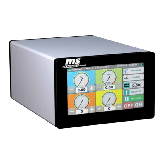
- Page 1 SERVICE MANUAL MS Elite Controller Model: 461959-XXXXB (Basic), 461959-XXXXD (Deluxe) 2813 ll 3(2) D. IP64 PA-19-08-R2 (02/2022) 1 / 32 www.carlisleft.com...
-
Page 2: Table Of Contents
CONTENTS CONTENTS SAFETY: Safety Precautions ................................ 3 Hazards / Safeguards ..............................4 APPROVALS (ATEX/FM/UKEX): MS elite Controller Model Identification ..........................8 ATEX/FM/UKEX: 10-11 European ATEX Directive .............................10 Labels ...................................11 PARTS IDENTIFICATION: 12-13 Scope of Delivery ................................. 12 MS Controller Options ..............................12 Powder Cord Options .............................. -
Page 3: Safety
This information relates to USER SAFETY and PREVENTING and safety literature for your equipment, contact your local EQUIPMENT PROBLEMS. To help you recognize this Carlisle Fluid Technologies representative or Carlisle Fluid information, we use the following symbols. Please pay Technologies technical support. -
Page 4: Hazards / Safeguards
SAFETY Return To Contents AREA SAFEGUARDS HAZARD Tells where hazards Tells how to avoid the hazard. Tells what the hazard is. may occur. Fire Hazard Spray Area Fire extinguishing equipment must be present in the Improper or inadequate spray area and tested periodically. operation and maintenance procedures will cause a fire Spray areas must be kept clean to prevent the... - Page 5 SAFETY Return To Contents AREA SAFEGUARDS HAZARD Tells where hazards Tells how to avoid the hazard. Tells what the hazard is. may occur. Explosion Hazard Spray Area Improper or inadequate Electrostatic arcing must be prevented. Safe sparking operation and maintenance distance must be maintained between the parts being procedures will cause a coated and the applicator.
- Page 6 SAFETY Return To Contents AREA SAFEGUARDS HAZARD Tells where hazards Tells how to avoid the hazard. Tells what the hazard is. may occur. Spray Area / Electrical Discharge High Voltage There is a high voltage device Parts being sprayed and operators in the spray Equipment that can induce an electrical area must be properly grounded.
- Page 7 SAFETY Return To Contents AREA SAFEGUARDS HAZARD Tells where hazards Tells how to avoid the hazard. Tells what the hazard is. may occur. Electrical Electrical Discharge Unless specifically approved for use in hazardous Equipment locations, the power supply, control cabinet, and all High voltage equipment is utilized in the process.
-
Page 8: Approvals (Atex/Fm/Ukex)
APPROVALS (ATEX/FM/UKEX) Return To Contents APPROVALS (ATEX/FM/UKEX) MS ELITE CONTROLLER MODEL IDENTIFICATION 461959 - AA B C D BASIC OR DELUXE CONTROLLER APPLICATOR DESIGNATIONS LANGUAGE PACK PLUG ASSEMBLY (POWER CORD) BASE MODEL NUMBER POWER CORD SELECTION “AA” Description Part # NONE NONE EU Plug Assembly... - Page 9 APPROVALS (ATEX/FM/UKEX) Return To Contents APPLICATOR DESIGNATION Description “C” Manual Application Automatic Application CONTROLLER DESIGNATION Description “D” Basic Deluxe Note: This unit is FM/ATEX approved for use inside the hazardous area. Refer to local governing bodies for proper use of this listed controller. www.carlisleft.com 9 / 32 PA-19-08-R2 (02/2022)
-
Page 10: Atex/Fm/Ukex
ATEX/FM/UKEX Return To Contents ATEX/FM/UKEX EUROPEAN ATEX DIRECTIVE 2014/34/EU, ANNEX II, UKSI 2016: 1107 (AS AMENDED) The following instructions apply to equipment covered by by suitably trained personnel in accordance with the certificate number FM 19ATEX0004X and FM21UKEX0140X: manufacturer's documentation. The equipment may be used with ignitable powders with The certification of this equipment relies upon the apparatus groups II and with temperature class T6. -
Page 11: Labels
ATEX/FM/UKEX Return To Contents MS Controller 461959-XXXXX ATEX Product Marking Definitions Ex Certificate Number: FM 19ATEX0004X and FM21UKEX0140X FM = Notified Body performing EU-type examination 19 = Year of examination ATEX = Reference to ATEX Directive 0004 = Document serial number X = Special conditions for safe use apply Product Marking II 3(2) D... -
Page 12: Parts Identification
PARTS IDENTIFICATION Return To Contents PARTS IDENTIFICATION This section identifies standard parts included when a MS elite controller system is delivered. Scope of Delivery The following items will be delivered as part of an MS controller order. SCOPE OF DELIVERY Part # Description 461959-XXXXB... -
Page 13: Powder Cord Options
PARTS IDENTIFICATION Return To Contents POWER CORD OPTIONS Depending on the optional designator used when the MS controller system was ordered, the customer may receive one power cord. The following table lists the power cord associated with each optional designator number. The power cord must be connected to a power source outside the classified zone. -
Page 14: Introduction
INTRODUCTION Return To Contents INTRODUCTION PRODUCT DESCRIPTION PRODUCT FEATURES The MS Controller is designed exclusively for the control of The MS Controller can be operated with the following MS Powder applicators. applicators: It controls and regulates the electrostatics and the air sup- ply for powder application. -
Page 15: Specifications
INTRODUCTION Return To Contents SPECIFICATIONS Dimension Weight: 6.4 kg (14.2 pounds) Depth: 332.0 mm (13.06 inches) Width: 200.6 mm (7.89 inches) Height: 128.6 mm (5.06 inches) Electrical data Main: 100 - 240 VAC Frequency: 50 - 60 Hz Input power: 70 W (With vibrator 550W) External voltage to applicator: max. -
Page 16: Installation
INSTALLATION Return To Contents INSTALLATION This section discusses how to install the MS controller. CAUTION WA R N I N G † DO NOT locate the controller near or adjacent to heat producing equipment such as ovens, high watt- † The user MUST read and be familiar with the age lamps, etc. -
Page 17: Main Supply Line Power
INSTALLATION Return To Contents In order to achieve a good powder coating and for safe- ty reasons (see safety regulations), the powder coating system must be properly grounded to true earth ground (copper rod driven into the ground). A ground cable is in- cluded with the controller. -
Page 18: Connecting Hardware - Ms Elite Basic Controller
INSTALLATION Return To Contents CONNECTING HARDWARE - MS ELITE BASIC CONTROLLER Controller Notice Connect What From Connector Name Control Module Connecting Ground Cable Controller True Earth Ground Safety Regulations Power Cable Line Power Main Supply Controller Safety Regulations Main Air Main Air Input Main Air Controller... -
Page 19: Connecting Hardware - Ms Deluxe Controller
INSTALLATION Return To Contents CONNECTING HARDWARE - MS ELITE DELUXE CONTROLLER Controller Notice Connect What From Connector Name Control Module Connecting Connect Ground Cable GND (Yellow/Green) Controller True Earth Ground Safety Regulations Power Cable Line Power Main Supply Controller Safety Regulations Main Air Main Air Input Main Air... -
Page 20: Operation
OPERATION Return To Contents OPERATION Select Display Language CAUTION Change the displayed language by pressing the globe button in the top right corner of the “WORK” screen. † Familiarize yourself with its operation before switching on the device. TOPCOAT PRG: 1 01/04/2019 10:18:47 STANDARD †... - Page 21 OPERATION Return To Contents Select a Powder Program Activating the Powder Applicator There are two pre-defined Powder Programs already load- Depending on the specific MS elite controller, either a ed on the MS elite controller. These Powder Programs Manual or an Automatic applicator may be attached. The have basic air, kV, and µA values set for a powder coating method to enable and trigger the applicator is slightly dif- session using either standard or metallic powder.
- Page 22 OPERATION Return To Contents Adjusting Powder Program Parameters STOP Adjust Powder Program parameters by pressing the num- ber within the gauge textbox and a numeric entry pad will appear. Then, you can enter any value you wish within the specified range for that particular operating parameter. Button appearance reflects the current state of the auto- 01/04/2019 10:18:47 TOPCOAT...
-
Page 23: Advanced Operations
OPERATION Return To Contents NOTE NOTE † “TWO LAYER” settings are always re-read from † The amount of adjustment (step size) that the “+” the selected Powder Program, so any adjustments and “–“ buttons apply to a parameter differs depend- that may have been made via the “WORK”... - Page 24 OPERATION Return To Contents 5. Navigate back to the “PROGRAMS” screen by pressing the “PROGRAMS” button. 6. Store the Powder Program, with its new parameter settings, by pressing the “SAVE PROGRAM” button. SAVE PROGRAM 7. Now when you select that program from the “PRO- GRAMS”...
-
Page 25: Configuration Settings Screens
OPERATION Return To Contents 2. Check to see if the Powder Program you want to delete is the active Powder Program by looking at the dark blue bar at the top of the “PROGRAMS” screen. • If the active Powder Program is not the Powder Pro- gram you wish to delete, first perform the following steps: - Select the Powder Program you wish to delete... -
Page 26: Configuration Settings - Screen #1
OPERATION Return To Contents Measurement Unit (of “WORK” Screen 3. Enter the password MS100 (Note: “CAP” is not Display Dials) highlighted) onto the keyboard and then press the “Enter” button. The first panel of buttons entitled “Measurement Unit” will allow switching between “WORK” screen configurations. Press a button to select that as the choice for gauges displayed on the “WORK”... -
Page 27: Configuration Settings - Screen #3
OPERATION Return To Contents Injector Type Gun Air Vibratory box fed hand carts 805700-XVBXXX-XXXX For Deluxe MS elite Controller units, gun air should always will always use the Elite Powder injector. The T9 injector be set with the “Proportional Valve” button selected and iused with automatic applicators and fluidized hopper carts green. -
Page 28: Ms Elite Controller - Parts List
OPERATION Return To Contents Deluxe Unit Shown MS CONTROLLER - PARTS LIST Description Part # 461959-XXXXB MS elite Controller (Basic) 461959-XXXXD MS elite Controller (Deluxe) 460146 Grounding Cable With Clamp 460147 Controller Power Cable (EU) 460148 Controller Power Cable (Switzerland) 460149 Controller Power Cable (USA/Japan) 460150... -
Page 29: Maintenance
MAINTENANCE Return To Contents MAINTENANCE 2. Replace the burnt out fuse with a new one. CAUTION 3. Place the fuse and holder back in the appropriate † All components inside the MS elite controller are opening in the back of the elite. Use a screwdriver to not accessible for servicing by the end-user. -
Page 30: Appendix
APPENDIX Return To Contents APPENDIX Work Screen Display Configuration - Bar: APPENDIX A: ADDITIONAL When the elite “WORK” screen Measurement Unit is con- NOTES ON WORK SCREEN figured for “Bar”, it appears as shown below. MEASUREMENT UNIT TOPCOAT PRG: 1 01/04/2019 10:18:47 (BAR, PSI, Nm STANDARD... - Page 31 APPENDIX Return To Contents 16/02/2019 00:08:39 TOPCOAT PRG: 3 TEST 40 50 PROGRAMS CLEANING Work Screen Display Configuration - Nm – – GUN AIR When the elite “WORK” screen Measurement Unit is con- 0.10 figured for “Nm /h”, it appears as shown below. 40 50 40 50 ONE LAYER...
- Page 32 WARRANTY POLICY This product is covered by Carlisle Fluid Technologies’ materials and workmanship limited warranty. The use of any parts or accessories, from a source other than Carlisle Fluid Technologies, will void all warranties. Failure to reasonably follow any maintenance guidance provided, may invalidate any warranty.
Need help?
Do you have a question about the MS Elite 461959 B Series and is the answer not in the manual?
Questions and answers