Table of Contents
Advertisement
Quick Links
Advertisement
Table of Contents

Related Manuals for ADTRAN 1200261L1


Summary of Contents for ADTRAN 1200261L1
- Page 1 ATLAS Quad USSI Module USER MANUAL Part Number 1200261L1 61200261L1-1A April 1999...
- Page 2 901 Explorer Boulevard P.O. Box 140000 Huntsville, AL 35814-4000 (256) 963-8000 © 1999 ADTRAN, Inc. All Rights Reserved. Printed in U.S.A.
- Page 3 ADTRAN Year 2000 (Y2K) Readiness Disclosure ADTRAN has established a Year 2000 program to ensure that our products will correctly function in the new millennium. ADTRAN warrants that all products meet Year 2000 specifications regardless of model or revision. Information about ADTRAN's Year 2000 compliance program is available at the fol-...
- Page 4 Warranty and Customer Service ADTRAN will replace or repair this product within five years from the date of shipment if the product does not meet its published specification, or if it fails while in service. For detailed warranty, repair, and return information, refer to the ADTRAN Equipment Warranty and Repair and Return Policy Proce- dure (see the last page of this manual).
-
Page 5: Table Of Contents
Physical Description ..........................1-2 Adapter Cable ............................1-2 Chapter 2. Installation ..........................2-1 Unpack and Inspect ............................2-1 Contents of ADTRAN Shipment ......................2-1 Wiring ................................2-1 Installing the ATLAS Quad USSI Module ....................2-2 Chapter 3. Operation..........................3-1 Overview ................................3-1 Password Security Levels .......................... - Page 6 Table of Contents > Inband STATS ............................... 3-6 > PLL/FIFO ............................... 3-6 > Configuration ..............................3-7 » Name................................3-7 » Clk (+/-) ..............................3-7 » Data ................................3-7 » CTS ................................3-7 » DCD ................................3-7 » DSR................................3-7 » DTR ................................3-7 »...
-
Page 7: List Of Figures
List of Figures Figure 1-1. ATLAS Quad USSI Module ........... 1-2 Figure 2-1. - Page 8 List of Figures viii ATLAS Quad USSI Module User Manual 61200261L1...
-
Page 9: List Of Tables
List of Tables Table 3-1. Normal Mode Operation......................3-8 Table B-1. Pinout for EIA-530 Cable......................B-1 Table B-2. Pinout for EIA-530A Cable ......................B-2 Table B-3. Pinout for RS-449 Cable......................B-2 Table B-4. Pinout for RS-232 Cable......................B-3 Table B-5. Pinout for CCITT X.21 (V.11) Cable..................B-3 Table B-6. - Page 10 List of Tables ATLAS Quad USSI Module User Manual 61200261L1-1...
-
Page 11: Chapter 1. Introduction
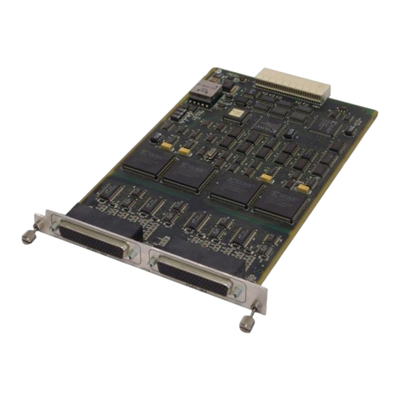
Introduction Chapter 1 ATLAS QUAD USSI MODULE OVERVIEW The ATLAS Quad USSI Module provides four synchronous DTE ports, each of which can operate at any rate that is a multiple of 56 or 64 kbps, up to 2.048 Mbps. You can install the ATLAS Quad USSI Module into any avail- able option slot of the ATLAS_800 chassis. -
Page 12: Module Specifications
Figure 1-1. ATLAS Quad USSI Module Adapter Cable Two ADTRAN-supplied adapter cables convert from the DB-78 connectors on the rear of the module to Dual D sub connectors. These connectors are marked as 1/3 and 2/4 to represent the port connected (1 or 3/2 or 4), based on the cable to which the DB-78 attaches. -
Page 13: Chapter 2. Installation
Carefully inspect the option module for any shipping damage. If damage is suspected, file a claim immediately with the carrier and then contact ADTRAN Technical Support. (See the last page of this manual for information on contacting Technical Support.) If possible, keep the original shipping container for returning the option module to ADTRAN for repair or for verification of damage during shipment. -
Page 14: Installing The Atlas Quad Ussi Module
Chapter 2. Installation INSTALLING THE ATLAS QUAD USSI MODULE Figure 2-1 represents the action required to properly position the ATLAS Quad USSI Module within the ATLAS chassis. Figure 2-1. Installing the Quad USSI Module Follow the steps below to install the option module: Instructions for Installing the ATLAS Quad USSI Module Step Action... -
Page 15: Chapter 3. Operation
Operation Chapter 3 OVERVIEW You can configure and control the ATLAS Quad USSI Module from a variety of sources, including the following: • The ATLAS Front Panel provides minimal configuration and status sup- port. • The terminal menu allows detailed configuration, status, and diagnos- tics. -
Page 16: Figure 3-1. Menu Tree
Chapter 3. Operation Refer to the ATLAS 800 User Manual for detailed instructions on how to navigate through the terminal menu. Quad USSI Info Part Number Serial Number SLIP Quad USSI Alarms ZERO NO EXT CLK DTE Status Name Type Data Rate Clk (+/–) Menu... -
Page 17: Menu Descriptions
Chapter 3. Operation Figure 3-2. Modules Menu MENU DESCRIPTIONS To help you follow the terminal menu hierarchy, the following notations are used. MAIN MENUS > » Submenus »» Sub-submenus > Read security: 5 Displays the number of available slots in the ATLAS chassis. Slot 0 refers to the ATLAS Base Unit. -
Page 18: Menu
Chapter 3. Operation MENU > Displays additional status and configuration menus for the selected module. (To access the menus options for this item, use the arrow keys to scroll to the Menu column for the module you want to edit, and press .) For detailed Enter information on each menu option, see ATLAS Quad USSI Module Menu Op-... -
Page 19: Atlas Quad Ussi Module Menu Options
Chapter 3. Operation ATLAS QUAD USSI MODULE MENU OPTIONS Figure 3-3 shows the menu options available for the ATLAS Quad USSI Module. The following sections describe these options. Figure 3-3. Quad USSI Module Menu Options QUAD USSI INFO > Read security: 5 Indicates the module status. -
Page 20: Dte Status
Chapter 3. Operation DTE STATUS > Read security: 5 Shows the status of the following key DTE interface signals (read-only). Request To Send from DTE Clear To Send to DTE Data Terminal Ready from DTE Data Set Ready to DTE Data Carrier Detect to DTE Ring Indicate to DTE Transmit Data from the DTE... -
Page 21: Configuration
Write security: 3; Read security: 5 Creates an 8 kbps management channel by robbing a bit from the first DS0 assigned to the port. This channel can manage remote ADTRAN products. » Send Leads Write security: 3; Read security: 5 Sends the state of the DTE leads to the remote unit whenever any DTE lead changes state. -
Page 22: Test
Chapter 3. Operation Table 3-1. Normal Mode Operation Conditions Causing Port Control Signal Deactivation Signal Follows — — V.54 Loopback — — 511 Test On Self-test Active — Network Test Active No DS0 Mapped Network Alarm — — = Do not care TEST >... -
Page 23: Loopback Status
Write security: 3; Read security: 5 Mode Controls the type of electrical DTE interface for the selected port. The Auto setting works with special ADTRAN cables to automatically detect the type of interface. » Current DTE Type Read security: 5 Displays the current electrical DTE interface type for the selected port. - Page 24 Chapter 3. Operation 3-10 ATLAS Quad USSI Module User Manual 61200261L1-1...
-
Page 25: Appendix A Dial Plan Interface Configuration
Dial Plan Interface Configuration Appendix A The User Term option for the Dial Plan menu sets the configuration param- eters for the end point for the ATLAS Quad USSI Module. The Dial Plan menus are only accessible when using terminal mode. To access these options, select Dial Plan from the top-level menu (see Figure A-1). - Page 26 Appendix A. Dial Plan Interface Configuration » Number of Ports Defines to ATLAS how many of the ports could be used to answer calls to the number(s) defined in the Accept Call list. You can enter numbers 1 through 4. The ports are contiguous beginning with the port number selected and the number of ports.
-
Page 27: Appendix B Pinouts
Pinouts Appendix B This appendix contains the pinout tables for the following wiring: • EIA-530 • EIA-530A • RS-449 • RS-232 • CCITT x.21 (V.11) • DB-78 connector Table B-1. Pinout for EIA-530 Cable Signal Description Signal Description Shield (Ground) Clear to Send (B) Transmit Data (A) Transmit Data (B) -
Page 28: Table B-2. Pinout For Eia-530A Cable
Appendix B. Pinouts Table B-2. Pinout for EIA-530A Cable Signal Description Signal Description Shield (Ground) Clear to Send (B) Transmit Data (A) Transmit Data (B) Received Data (A) Transmit Clock (A) Request to Send (A) Received Data (B) Clear to Send (A) Receive Clock (A) DCE Ready (A) Local LoopBack*... -
Page 29: Table B-4. Pinout For Rs-232 Cable
Appendix B. Pinouts Table B-4. Pinout for RS-232 Cable Signal Description Signal Description Shield (Ground) Sec. Transmit Data Transmit Data DCE Transmit Clock Received Data Sec. Received Data Request to Send Receive Signal Element Timing Clear to Send Not used Data Set Ready Sec. -
Page 30: Table B-6. Pinout For The Db-78 Connector
Appendix B. Pinouts Table B-6. Pinout for the DB-78 Connector Signal Description Signal Description RXD-A 2/4 RTS-B 2/4 RXD-B 2/4 43—48 RXC-A 2/4 NOT USED RXC-B 2/4 MOD2 TXD-A 2/4 MOD0 TXD-B 2/4 EXT-TXC-A 1/3 TXC-A 2/4 DTR-B 1/3 TXC-B 2/4 DTR-A 1/3 EXT-TXC-A 2/4 DCD-B 1/3... - Page 31 Index Numerics DTR 3-6 0 Inh (zero inhibit) menu 3-7 FCC statement iv features 1-1 alarms NO EXT CLK 3-5 PLL 3-5 SLIP 3-5 hardware revision 3-4 Zero 3-5 alarms menu 3-4 ATLAS front panel 3-1 inband menu 3-7 inband statistics 3-6 info menu 3-5 changing modules 3-3 inject error 3-9...
- Page 32 Index slt (slot) 3-3 password 3-1 state 3-4 password security level 3-1 status 3-4 pattern generator and detector test 3-9 test 3-4 PLL alarm 3-5 type 3-3 PLL/FIFO 3-6 Quad USSI 3-5 ports available, dial plan A-1 alarms NO EXT CLK 3-5 PLL 3-5 Quad Nx 56/64 SLIP 3-5...
- Page 33 Index loopbk 3-8 wiring for the Quad USSI 2-1 type menu 3-3 Y2K iii VT-100 terminal emulation 3-1 year 2000 compliancy iii warranty and customer service iv Zero alarm 3-5 61200261L1-1 ATLAS Quad USSI Module User Manual Index-3...
-
Page 34: Index
Index Index-4 ATLAS Quad USSI Module User Manual 61200261L1-1... - Page 35 Technical Support Repair and Return If ADTRAN Technical Support determines that a repair is needed, Technical Support will coordinate with the Customer and Product Service (CAPS) department to issue an RMA number. For information regarding equipment currently in house or possible fees associated with repair, contact CAPS directly at the following...
Need help?
Do you have a question about the 1200261L1 and is the answer not in the manual?
Questions and answers