Advertisement
Quick Links
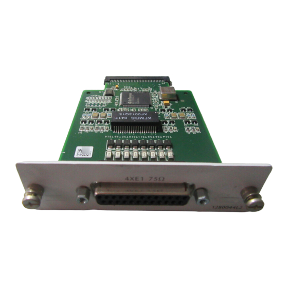
TRACER QUAD E1 MODULE
Quick Start Guide
DB-25 C
P
ONNECTION
INOUT
Pin
Name
1
E1D RX TIP
2
E1D TX TIP
3
GND
4
E1C RX TIP
5
E1C TX TIP
6
GND
7
E1B RX TIP
8
E1B TX TIP
9
GND
10
E1A RX TIP
11
E1A TX TIP
12-25
GND
Quick Start Guide, 61280044L2-13A, February 2005
Description
Receive signal for E1 D interface
Output signal for E1 D interface
Ground
Receive signal for E1 C interface
Output signal for E1 C interface
Ground
Receive signal for E1 B interface
Output signal for E1 B interface
Ground
Receive signal for E1 A interface
Output signal for E1 A interface
Ground
Technical Support 1-888-4ADTRAN (1-888-423-8726)
For more detailed documentation, visit us online at
S
PECIFICATIONS
Capacity:
4xE1 (CCITT G.703) – 8.192 Mbps
Interface Type:
G.703, G.704, and G.823 Compliant (BNC interfaces only)
Connectors:
DB-25 with optional breakout panel providing 75Ω BNCs
Line Code:
HDB3 (default), AMI
Alarms:
LOS, LCV, AIS, RMT, OOF, CRC
Loopbacks:
Local and remote line, local and remote link
I
I
NSTALLATION
NSTRUCTIONS
The TRACER Quad E1 Module is not
hot-swappable. Remove power from the TRACER
system before installing or removing the module.
1. Remove the cover plate from the appropriate option slot in the TRACER
rear panel.
2. Slide the TRACER Quad E1 Module into the option slot until the module
is firmly positioned in the chassis.
3. Secure the thumbscrews at both edges of the module. Tighten with a
screwdriver.
4. Connect the cables to the associated device(s).
5. Complete installation of remaining modules and system as specified in
the TRACER 6000 Series System Manual.
www.adtran.com
P/N 1280044L2
Copyright © 2005 ADTRAN, All Rights Reserved
Advertisement

Related Manuals for ADTRAN TRACER QUAD E1


Summary of Contents for ADTRAN TRACER QUAD E1
- Page 1 Receive signal for E1 C interface rear panel. E1C TX TIP Output signal for E1 C interface 2. Slide the TRACER Quad E1 Module into the option slot until the module is firmly positioned in the chassis. Ground E1B RX TIP Receive signal for E1 B interface 3.
- Page 2 The 75Ω unbalanced interfaces provided by the breakout panel are available for connection to standard E1 DTE devices (see Figure 1). 1. E1 C IGURE ONNECTION WITH REAKOUT ANEL Copyright © 2005 ADTRAN, All Rights Reserved Quick Start Guide, 61280044L2-13A, February 2005 Technical Support 1-888-4ADTRAN (1-888-423-8726)
Need help?
Do you have a question about the TRACER QUAD E1 and is the answer not in the manual?
Questions and answers