Table of Contents
Advertisement
Quick Links
Advertisement
Table of Contents

Related Manuals for ADTRAN T3


Summary of Contents for ADTRAN T3
- Page 1 T3 Module USER MANUAL Part Number 1200223L1 / 1200225L1 61200223L1-1A July 1998...
- Page 2 901 Explorer Boulevard P.O. Box 140000 Huntsville, AL 35814-4000 (256) 963-8000 © 1998 ADTRAN, Inc. All Rights Reserved. Printed in U.S.A.
- Page 3 Shielded cables must be used with this unit to ensure compliance with Class A FCC limits. Change or modifications to this unit not expressly approved by the party responsible for compliance could void the user’s authority to operate the equipment. 61200223L1-1 T3 Module User Manual...
- Page 4 T3 Module User Manual 61200223L1-1...
-
Page 5: Table Of Contents
Terminal Menu Structure ............................ 3-1 Menu Access ............................... 3-2 T3 Module Menu Descriptions ........................... 3-2 T3 Module Modules Submenus .......................... 3-4 ATLAS 800 Features used with T3-1 or T3-2 Modules ................... 3-16 Factory Restore............................3-16 Run Self-Test ............................. 3-16 Mapping..............................3-16 Appendix A. - Page 6 Table of Contents T3 Module User Manual 61200223L1-1...
- Page 7 Figure 3-2. T3-2 Menus Screen........................3-4 Figure 3-3. T3 Info Screen ..........................3-4 Figure 3-4. MUX Configuration Screen ....................... 3-5 Figure 3-5. T3 Alarm Status Screen ......................3-6 Figure 3-6. T3 Performance (Current) Screen ..................... 3-7 Figure 3-7. T3 Configuration Screen ......................3-8 Figure 3-8.
- Page 8 List of Figures viii T3 Module User Manual 61200223L1-1...
- Page 9 List of Tables Table 2-1. Network Connection ........................2-2 Table 3-1. Management Approaches ......................3-1 Table 3-2. Status Messages .......................... 3-3 61200223L1-1 T3 Module User Manual...
- Page 10 List of Tables T3 Module User Manual 61200223L1-1...
-
Page 11: Chapter 1. Introduction
T3 D/I module has two T3 interfaces. The T3 D/I module may terminate between 2 and 28 T1s as the T3 into the ATLAS and pass through the remaining bandwidth out of the secondary T3 port. The secondary T3 port may not be used to terminate bandwidth on the ATLAS, but passes the T1s back out the primary T3 interface. -
Page 12: Functional Description
Figure 1-1. T1 Bandwidth Management Application FUNCTIONAL DESCRIPTION The T3 Module can be installed in any available option slot in the ATLAS chassis. The status of the module itself, as well as the circuits to which it interfaces, can be viewed from the ATLAS front panel. -
Page 13: T3 Module Specifications
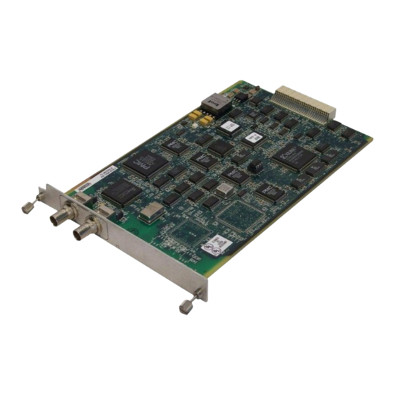
75 ohms + 5%, unbalanced Impedance PHYSICAL DESCRIPTION The T3 Module plugs into any available option slot in the rear of the ATLAS 800 (see Figure 1-2). Figure 1-2. T3 Module The T3 Module has a label over each pair of BNC connectors referring to the port on the card. - Page 14 Chapter 1. Introduction T3 Module User Manual 61200223L1-1...
-
Page 15: Chapter 2. Installation
Remove the option slot cover plate from the ATLAS 800 rear panel. Slide the T3 Module into the option slot until the module is firmly positioned against the front of the chassis. Fasten the thumbscrews at both edges of the T3 Module. -
Page 16: Wiring
The T3 Module automatically executes a self-test when it powers up. Any previ- ously configured setting for the T3 Module is automatically restored upon power up. If the T3 Module fails one or more of the self-tests executed during power up, an error message is displayed on the LCD. -
Page 17: Chapter 3. Operation
The ATLAS System Controller automatically detects the presence of the T3 Mod- ule when it is installed in the system. You can configure and control the T3 Mod- ule from several sources. Table 3-1 shows the various sources, their purpose, and their access. -
Page 18: Menu Access
Displays the type of module currently installed in the slot or the module type you plan to install in the slot. For instance, if a T3 Module is installed, the Type field automatically defaults to T3-1 or T3-2. You can use this field to preconfigure a sys- tem before installing modules;... - Page 19 A module must be in the Online state in order for ATLAS to use the module for any data bandwidth. Status Read security: 5 Displays status information on the T3 Module. Table 3-2 on page 3-3 describes sta- tus messages that may display. Rev (Hardware Revision) Read security: 5 Displays the hardware revision of the T3 Module.
-
Page 20: T3 Module Modules Submenus
Chapter 3. Operation T3 MODULE MODULES SUBMENUS Figure 3-2 shows the Menu submenu options for the T3-1 and T3-2 Modules. The following sections describe these options. Figure 3-2. T3-2 Menus Screen T3-2 Menus Read security: 5 Displays module configuration and status information. -
Page 21: Figure 3-4. Mux Configuration Screen
This field shows the number of T1s from the T3-2 module available to terminate in the ATLAS 800. T1s Passed Thru This field shows the number of T1s from the T3 module that are passed out the secondary T3 interface to other equipment. -
Page 22: Figure 3-5. T3 Alarm Status Screen
Chapter 3. Operation T3 Alarm Status Read security: 5 Indicates the current alarm status of the T3 interface (see Figure 3-5). Figure 3-5. T3 Alarm Status Screen Indicates the port number. Alarms Lists the following alarms: FE Alarms (Far End Alarms) (Loss of Signal) Detects no signal at T3 port interface. -
Page 23: Figure 3-6. T3 Performance (Current) Screen
Chapter 3. Operation Figure 3-6. T3 Performance (Current) Screen Indicates port number. CLR[+] Write security: 3 Clears all of the counts to 0 for the selected port when you scroll to this field and press RETURN. ES_L Count of seconds containing excessive zeros, (Errored Seconds - Line) LOS, or BPVS, not due to line code substitutions. -
Page 24: Figure 3-7. T3 Configuration Screen
Chapter 3. Operation T3 Configuration Write security: 3; Read security: 5 Includes all of the configurable parameters pertaining to the T3 interface in this menu chain (see Figure 3-7). Figure 3-7. T3 Configuration Screen Port number of the T3 module. -
Page 25: Figure 3-8. T3 Test Screen
Line - T3 line loopback active Remote Indicates if loopbacks initiated from remote sources are in effect and may be used to execute remote loopbacks on the far-end T3. None - No remote loopbacks are activated. DS3 Line - Remote DS3 line loopback is activated. -
Page 26: Figure 3-9. T1 Alarm Status Screen
Port receiving remote alarm indication (RAI). Blue Receiving unframed 1s from the port; also called AIS. D-Chan D channel alarm is only meaningful if T1 is defined as a PRI. (Requires using an HDLC controller on another card.) 3-10 T3 Module User Manual 61200223L1-1... -
Page 27: Figure 3-10. T1 Ds0 Status Screen
Indicates signaling of all 24 DS0s. The A/B bits for Rx (receive) and Tx (trans- mit) DS0s are shown for each port. Dashes display for those DS0s where robbed-bit signaling is not being transferred by the ATLAS 800 (see Figure 3- 11). 61200223L1-1 T3 Module User Manual 3-11... -
Page 28: Figure 3-11. T1 Signal Status
AT&T TR54016 for each of the T1 ports for each performance field (either current, 15-minute total, or 24-hour total). Excepting CLR, these fields are all read-only (see Figure 3-12). Figure 3-12. T1 Performance (Current) Screen 3-12 T3 Module User Manual 61200223L1-1... -
Page 29: Figure 3-13. T1 Configuration Screen
Severely Errored Frame Seconds. LOFC Loss of Frame Count. Controlled Slip Seconds. Unavailable Seconds. T1 Configuration Various security levels apply for these configurable parameters (see also Fig- ure 3-13). Figure 3-13. T1 Configuration Screen 61200223L1-1 T3 Module User Manual 3-13... -
Page 30: Figure 3-14. T1 Test Screen
Read security: 5 Displays the port number. Port Name Write security: 3; Read security: 5 Allows users to identify each port on the T3 Module with a unique alpha-numeric name. Names can be up to 16 characters long. Frame Write security: 2; Read security: 5 Set this field to match the frame format of the circuit to which it is connected, available from the network supplier. -
Page 31: Figure 3-15. Network Loopback Test
Injects errors into transmitted test pattern. (Inject Test Pattern Error) T3 Module T1 Payload Loopback T1 Line Loopback T3 Line T1 Framer #1 Loopback T3 Line Front T1 Framer Figure 3-15. Network Loopback Test 61200223L1-1 T3 Module User Manual 3-15... -
Page 32: Atlas 800 Features Used With T3-1 Or T3-2 Modules
Chapter 3. Operation ATLAS 800 FEATURES USED WITH T3-1 OR T3-2 MODULES In addition to the T3 Module menu items, two other ATLAS 800 menu items may be operated in conjunction with the T3 Modules. These items are Factory Restore and Run Self-Test. -
Page 33: Appendix A Dial Plan Interface Configuration
T3 MODULE INTERFACE CONFIGURATION This section describes the network termination and user termination configura- tion settings for the T3-1 and T3-2 Modules when using the Dial Plan menus. These menus represent the T3 Module as having 28 T1 ports to configure. - Page 34 T3 Module (Network Termination/RBS) When you are working in the Network Termination section of the Dial Plan menu, Slot is defined as a T3-1 or T3-2 Module, and Sig is set to RBS, the following inter- face configuration options are available: First DS0 Write security: 2;...
- Page 35 T3 Module (User Termination/RBS) When you are working in the user termination section of the Dial Plan menu, when the Slot is defined as a T3-1 or T3-2 module, and when Sig is set to RBS, the following configuration options are available: First DS0/Number of DS0s Write security: 3;...
- Page 36 Enabled, then the following information must be defined: DID Digits Transferred Defines the number of digits the ATLAS 800 sends on to the user equip- ment. This field only displays if direct inward dialing is set to Enabled. T3 Module User Manual 61200223L1-1...
- Page 37 This option only dis- plays if direct inward dialing is set to Disabled. This item is optional. The Caller ID number must be specific (i.e., no “wild cards”). 61200223L1-1 T3 Module User Manual...
- Page 38 Appendix A. Dial Plan Interface Configuration T3 Module User Manual 61200223L1-1...
- Page 39 2-1 interface configuration default settings 3-16 Quad T1/PRI A-1 description introduction 1-1 functional 1-2 physical 1-3 disrupted service 3-14 line codes 1-3 DS0s, number of A-2 line rate 1-3 local loopback 3-15 loopback 61200223L1 T3 Module User Manual Index-1...
- Page 40 1-1 T1 DSO status 3-11 T1 performance current, 15min, 24Hr 3-12 performance current 3-12 3-13 physical description 1-3 3-13 port 3-13 T3 alarm status 3-6 3-13 power up 2-2 LOFC 3-13 3-13 SEFS Quad T1/PRI 3-13 interface configuration A-1...
- Page 41 Prt 3-15 T3 test 3-9 QRSS/RLB results 3-15 loopback 3-9 remote LB 3-15 none remote loopback 3-15 PRT 3-9 T3 alarm status 3-6 remote LB 3-9 alarms 3-6 DS1 #1... DS1 #28 FE alarms DS1 all BLUE 3-6 CBI 3-6...
- Page 42 PRT 3-9 remote LB 3-9 warranty 2-2 DS1 #1... DS1 #28 3-9 wiring 2-2 DS1 all 3-9 DS3 line 3-9 none 3-9 yellow alarm remote status 3-9 auto TX 3-14 line loopback active 3-9 Index-4 T3 Module User Manual 61200223L1...
- Page 43 (888) 4ADTRAN Repair and Return If ADTRAN Technical Support determines that a repair is needed, Technical Support will coordinate with the Customer and Product Service (CAPS) department to issue an RMA number. For information regarding equipment currently in house or possible fees associated...
Need help?
Do you have a question about the T3 and is the answer not in the manual?
Questions and answers