Table of Contents
Advertisement
Quick Links
Advertisement
Table of Contents

Related Manuals for Beckhoff CP79-0010 Series


Summary of Contents for Beckhoff CP79-0010 Series
- Page 1 Manual | EN CP79xx-xxxx-0010 Control Panel 2023-10-11 | Version: 1.3...
-
Page 3: Table Of Contents
Table of contents Table of contents 1 Notes on the documentation........................ 5 2 For your safety ............................ 6 Signal words............................ 6 Intended use ............................. 6 Fundamental safety instructions ....................... 7 Operator's obligation to exercise diligence.................. 7 Notes on information security...................... 8 3 Product overview ............................ - Page 4 Table of contents Version: 1.3 CP79xx-xxxx-0010...
-
Page 5: Notes On The Documentation
Copyright © Beckhoff Automation GmbH & Co. KG. Publication of this document on websites other than ours is prohibited. Offenders will be held liable for the payment of damages. All rights reserved in the event of the grant of a patent, utility model or design. -
Page 6: For Your Safety
Exclusion of liability Beckhoff shall not be liable in the event of non-compliance with this documentation and thus the use of the devices outside the documented operating conditions. -
Page 7: Fundamental Safety Instructions
For your safety Fundamental safety instructions The following safety instructions must be observed when handling the the Control Panel. Application conditions • Do not use the device under extreme environmental conditions. • Only use the device in hazardous areas if it is explicitly designed for this purpose. •... -
Page 8: Notes On Information Security
For your safety Notes on information security The products of Beckhoff Automation GmbH & Co. KG (Beckhoff), insofar as they can be accessed online, are equipped with security functions that support the secure operation of plants, systems, machines and networks. Despite the security functions, the creation, implementation and constant updating of a holistic security concept for the operation are necessary to protect the respective plant, system, machine and networks against cyber threats. -
Page 9: Product Overview
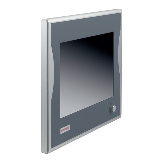
Product overview Product overview The Economy Control Panel is designed for installation on the mounting arm and is available in a wide range of diagonals. It can be used for a wide range of automation tasks. The control panel has the following features: •... -
Page 10: Structure
Product overview Structure Figure 1 shows the structure of the device as an example of all CP79xx versions. Fig. 1: CP79xx_structure Table 1: Key CP79xx structure Component Description 4 threaded holes M6 x 18 mm For installation on the wall Name plate Information on the control panel equipment Connection section Access to interfaces... -
Page 11: Interface Description
Product overview Interface description In the basic configuration, the control panel includes the following interfaces: • DVI Extended input (X101) • Power supply (X102) • USB Extended 2.0 input (X103) The interfaces are located at the rear of the control panel (see fig. 2). In the case of 6.5-inch and 12-inch displays, the interfaces are located on the back at the bottom right. -
Page 12: Dvi Extended Input
Product overview 3.2.1 DVI Extended input The control panel has a DVI Extended input (X101) according to IP65. It is used to transmit the graphics signal from the industrial PC to the control panel. The graphics signal is transferred directly via a DVI cable over a distance of 50 m max. Such a cable length leads to strong distortion of the graphics signal on arrival at the control panel. -
Page 13: Power Supply
The plug is included in the delivery. You can obtain a replacement plug from your Beckhoff Sales using the following ordering option: • C9900-P916: power supply connector for CP79xx, round connector IP65 with strain relief for the external supply cable 3.2.3... -
Page 14: Fig. 6 Cp79Xx_Name Plate
Product overview xxxxxxx Fig. 6: CP79xx_name plate Table 5: Legend CP79xx name plate Description Model: the last four digits indicate the product version. Serial number (BTN) Date of manufacture Display Touch screen Touch pad Controller Symbols Note: here are the symbols applicable to the device such as CE, EAC, UKCA, . -
Page 15: Key Functions
Product overview Key functions You can order your control panel with different versions of the front laminate. You can choose between a panel without buttons and a panel with different button configurations. Please refer to the current price list for specific ordering options. - Page 16 Product overview Opening the properties window of a selected object Esc = close dialog box, cancel operations Set printed character to the cursor position … Function keys = functions of the keys determined by the software Special keys = special keys with LED that can be controlled by the TwinCAT automation software Einschub Einschub...
-
Page 17: Connection Kits
Product overview Connection kits The following optional connection kits are available: Table 7: CP79xx connection kits Connection kits Description C9900-K630 3 m connection kit for CP79xx-xxxx-0010, consisting of: 3 m DVI cable, 3 m Cat.5 cable for USB-E-2.0, CU8801 USB-to-USB-E-2.0 converter for DIN rail mounting next to the PC and 1 m USB cable for connecting the USB-to- USB-E-2.0 converter to the PC C9900-K631 5 m connection kit for CP79xx-xxxx-0010, consisting of:... -
Page 18: Commissioning
If you, as the user, require additional protection for the touch screen against dirt and scratching, for example due to dirty hands, this can be achieved with a Beckhoff protective film. The film provides short-term protection for a few days. -
Page 19: Transport And Unpacking
Extreme environmental conditions can cause damage to the device. • Avoid extreme environmental conditions. • Protect the device against dust, moisture and heat. Dimensions The dimensions of the control panel can be found on the Beckhoff website: https://www.beckhoff.com/de- de/support/downloadfinder/technische-zeichnungen/. All dimensions are in mm. Connecting the control panel... -
Page 20: Grounding The Control Panel
Commissioning To prepare the control panel for operation, you have to connect it. The first step is to ground the device. Then you can connect the cables and the power supply. An external power supply unit providing 24 V DC (-15 %/+20 %) from an isolated source is required for the power supply. - Page 21 Commissioning NOTICE Hardware damage due to electromagnetic interference Using the control panel without functional earth can lead to hardware damage due to electromagnetic interference. • Only use the device with functional earth. Electromagnetic compatibility (EMC) of the control panel includes on the one hand not affecting other devices and equipment by electromagnetic interference and on the other hand not being disturbed by electrical or electromagnetic effects itself.
-
Page 22: Connecting Cables And Power Supply
When connecting the control panel to an industrial PC with UPS output, Beckhoff recommends using this for the connection so that the display is also active in UPS mode. Only one control panel may be connected to the UPS output on the PC. -
Page 23: Decommissioning
Decommissioning Decommissioning NOTICE Hardware damage due to power supply A connected power supply can cause damage to the control panel during disassembly. • Disconnect the power supply from the device before starting to disassemble it. When taking the control panel out of operation, you must first disconnect the power supply and cables. You can then dismantle the device. -
Page 24: Maintenance
Cleaning the front screen You can clean the front screen of the control panel during operation. In order to avoid inadvertent touch entries when doing this, you must first set the device to "Cleaning Mode" with the help of the Beckhoff Control Tool. -
Page 25: Fig. 8 Cp69Xx_Select Cleaning Mode
5 and 120 seconds. Right-click the sun symbol again and click "Options". Now select the appropriate period (see fig. 9). Fig. 9: CP69xx_Options Repair Only the vendor may repair the device. If a repair should be necessary, contact Beckhoff Service (see Chapter 9.1 Service and Support [} 28]). CP79xx-xxxx-0010 Version: 1.3... -
Page 26: Troubleshooting
Cycle time in TwinCAT set to 10 ms Increase the cycle time to TwinCAT via USB (standard) between 50 ms and 80 ms No picture/backlight Problem with the cable connections Check the cable connection Beckhoff recommends using Beckhoff connection cables and connection kits. Version: 1.3 CP79xx-xxxx-0010... -
Page 27: Technical Data
CP79xx Supply voltage 22-30 V (24 V power supply unit, NEC class 2) Power consumption Data sheet for calculating power consumption and power loss in the download finder: https://www.beckhoff.com/de-de/support/downloadfinder/ suchergebnis/?c-1=40717316 Protection rating IP65 Vibration resistance (sinusoidal EN 60068-2-6: 10 ... 58 Hz: 0.035 mm vibration) 58 ... -
Page 28: Appendix
33415 Verl Germany Phone: + 49 5246/963-0 email: info@beckhoff.de The addresses of the worldwide Beckhoff branches and agencies can be found on our website at http:// www.beckhoff.com/. You will also find further documentation for Beckhoff components there. Version: 1.3 CP79xx-xxxx-0010... -
Page 29: Approvals
Appendix Approvals Your device has the following approvals: • CE • EAC • UKCA • FCC You will find all other applicable approvals on the name plate of your device. FCC approvals for the United States of America FCC: Federal Communications Commission Radio Frequency Interference Statement This device was tested and complies with the limits for a digital device of class A, according part 15 of the FCC regulations. - Page 30 List of figures List of figures Fig. 1 CP79xx_structure......................... Fig. 2 CP79xx_connection section......................Fig. 3 CP79xx_DVI Extended input pin numbering................Fig. 4 CP79xx_voltage socket pin numbering..................Fig. 5 CP79xx_USB-E 2.0 input pin numbering ..................Fig. 6 CP79xx_name plate........................Fig. 7 CP79xx_protective conductor connection..................
- Page 31 List of tables List of tables Table 1 Key CP79xx structure ........................Table 2 DVI Extended interface pin assignment ..................Table 3 Voltage socket pin assignment ....................Table 4 USB E 2.0 input pin assignment ....................Table 5 Legend CP79xx name plate......................Table 6 Key functions CP79xx ........................
- Page 33 More Information: www.beckhoff.com/cp79xx Beckhoff Automation GmbH & Co. KG Hülshorstweg 20 33415 Verl Germany Phone: +49 5246 9630 info@beckhoff.com www.beckhoff.com...
Need help?
Do you have a question about the CP79-0010 Series and is the answer not in the manual?
Questions and answers