Table of Contents
Advertisement
Quick Links
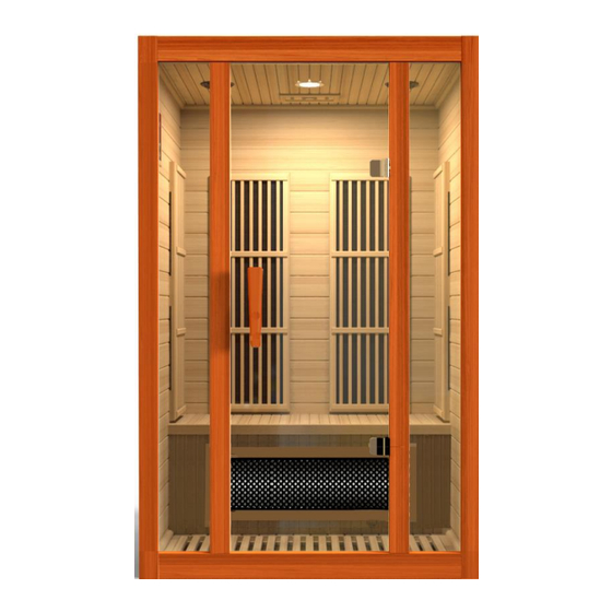
Model: MX-J206-02S & MX-J306-02S
FOR CARBON MODEL SAUNAS
HEMLOCK WOOD SAUNA MODELS
FOR INDOOR USE ONLY
MX-J206-02S: 120V/15AMP DEDICATED CIRCUIT REQUIRED
MX-J306-02S: 120V/20AMP DEDICATED CIRCUIT REQUIRED
Carefully and thoroughly read this Owner's Manual before using/operating
the sauna. We recommend keeping this Owner's Manual for regular review
and future reference.
1
Advertisement
Table of Contents

Related Manuals for Golden Designs MX-J306-02S


Summary of Contents for Golden Designs MX-J306-02S
- Page 1 HEMLOCK WOOD SAUNA MODELS FOR INDOOR USE ONLY MX-J206-02S: 120V/15AMP DEDICATED CIRCUIT REQUIRED MX-J306-02S: 120V/20AMP DEDICATED CIRCUIT REQUIRED Carefully and thoroughly read this Owner’s Manual before using/operating the sauna. We recommend keeping this Owner’s Manual for regular review and future reference.
-
Page 2: Table Of Contents
TABLE OF CONTENTS Packing List Visual Assembly Diagrams Parts Description Assembly Instructions Operating the Sauna Tips for Using Your Sauna Safety Instructions Safeguards for Your Sauna Troubleshooting Guide Warranty Warranty Card WARNING: Visually inspect all heaters before assembly to make sure they are not damaged. - Page 3 What Are Infrared Rays? Infrared is the band of light we perceive as heat. We cannot see this band of light with the naked eye, but we can feel this type of light in the form of heat. Our sun produces most of its energy output in the infrared segment of the spectrum.
- Page 4 EMF Levels from Common Homes Sources After many years and numerous studies on EMF exposure, no government body including the Occupational Safety and Health Administration (OSHA) have established permissible exposure limits (PEL). Currently, there is no consensus on the potential health hazard from any exposure to EMF.
- Page 5 HOW IT WORKS Infrared Saunas differ from traditional saunas in that they use infrared radiant energy to directly penetrate into the body's tissue to produce perspiration. Traditional saunas use steam to heat the air inside the sauna, which then heats your body until you begin to perspire.
-
Page 6: Visual Assembly Diagrams
*PLEASE READ INSTRUCTIONS BEFORE ASSEMBLY* Visual Assembly Diagram MX-J206-02S *The above assembly diagrams are for quick reference visual guides only. All sauna models are not shown. Parts and accessories may vary. Parts subject to change. - Page 7 *PLEASE READ INSTRUCTIONS BEFORE ASSEMBLY* Visual Assembly Diagram MX-J306-02S *The above assembly diagrams are for quick reference visual guides only. All sauna models are not shown. Parts and accessories may vary. Parts subject to change.
-
Page 8: Parts Description
PARTS DESCRIPTION *The above assembly diagrams are for quick reference visual guides only. All sauna models are not shown. Parts and accessories may vary. Parts subject to change. - Page 9 PARTS DESCRIPTION *The above assembly diagrams are for quick reference visual guides only. All sauna models are not shown. Parts and accessories may vary. Parts subject to change.
- Page 10 *PLEASE READ INSTRUCTIONS THOROUGHLY BEFORE ASSEMBLY* Highlights A. High quality craftsmanship B. Temperature control C. Timer D. Infrared carbon heat emitter panels E. Control Panel: F. Power supply: G. MP3 Jack: Buckles:...
- Page 11 Assembly Pictures shown are for representation only and may not resemble your exact model. Please note the following: A. You will need a Philips screwdriver, ladder, and two adults to assemble. B. Do not plug any other appliances into the power supply of the sauna room other than the designated sauna connections/plugs.
- Page 12 2. Align the Back Panel by placing it up and onto the Floor Panel. It should sit up against the quarter round trim molding on the Floor Panel. One person should hold the Back Panel while the other person continues to the next step. (see FIG 4) FIG 4 Assembling Back Panel 3.
- Page 13 4. Latch the Right Side Panel with the Back Panel. The buckle has a guide tab that must be placed in the guide slot for alignment. When the Back Panel and the Side Panel is attached together on the floor panel, make sure all the buckles are latched. (see Figure 6) FIG 6 Buckle 5.
- Page 14 6. Place the Floor Heater on the Floor Panel making sure that the Floor Heater is in front of the Bench Heat Emitter Panel. Please note there is a pre-cut small hole under the Bench Heat Emitter Panel which is provided for the Floor Heater cord. This cord will connect the Floor Heater to the plug outlet on the Left Side Panel.
- Page 15 FIG 11 Assembling Front Panel 9. Place cords/wires of Side Panel and Back Panel into the sauna room area to avoid damaging the cords/wires during the roof installation. Open the door, lift the Roof Panel up and over the sauna room, and gently lower it into place resting it on the wall panels.
- Page 16 FIG-13 Connecting cords/wires connectors 11. Make sure all steps are completed correctly. Next, plug in the power cord to your wall outlet. Turn on the sauna at the control panel to confirm that the control panel is responding. If the control panel responds accordingly, then proceed in putting the Roof Cover onto the Roof Panel.
-
Page 17: Operating The Sauna
FIG 19 Temperature Sensor Installation Completed. Operating the Sauna NOTE: Please check and confirm that the connections to the POWER SUPPLY, HEAT EMITTERS, and TEMPERATURE SENSOR are connected properly. The power supply voltage and frequency must match the requested voltage and frequency of the sauna (120VAC 15AMP Dedicated Circuit or 120VAC 20AMP Dedicated Circuit). - Page 18 1. Precautions a. Please make sure your wall outlet meets the specifications required. Failure to meet the requirements may cause safety risks. b. Set the temperature and time to a comfortable level. The average used temperature range is between 118ºF – 122ºF. The average sauna session is approximately 20 – 30 minutes. It is recommended that you pre-heat the sauna room to the desired temperature before entering.
- Page 19 After your sauna session is over, you can turn the control panel off by pressing the ON/OFF button. You can unplug the sauna cord to protect the electronics from power surges. g. To set the time, press the buttons. Press buttons to set the timer from 5 to 60 minutes.
-
Page 20: Tips For Using Your Sauna
Use 2 towels during your sauna session. Fold the first towel several times and place it on the bench. As you sit on this towel, it will absorb a majority of your perspiration while adding comfort as you sit on the bench. Use the second towel to either constantly wipe the perspiration from your body to perspire faster and also to avoid having too much perspiration dripping onto the floor. -
Page 21: Safety Instructions
comfortable, you can exit the sauna. After about fifteen minutes and when your body has completely cooled down, you can take a shower or bath to clean your body. Safety Instructions 1. Read and follow all instructions carefully before using the sauna. 2. -
Page 22: Safeguards For Your Sauna
15. Make sure that the electrical outlet is in good working order. A common problem with electrical outlets is loose wiring on the connection points of the terminals of the outlet. A loose wire will also make for a bad connection and cause an unusual amount of heat buildup. -
Page 23: Troubleshooting Guide
requirements of the manufacturer. Unauthorized substitutes may result in a fire, electrical shock, or other hazardous situations. After any repairs, please ask the service technician to perform a safety check to determine that the sauna is in good working order. 5. - Page 24 troubleshooting. Solution: The control panel will not turn off, the power/work/or heat lights do not come on, or the temperature and timer buttons do not work means the control panel may have been damaged and will need to be replaced. Contact the manufacturer for additional troubleshooting.
- Page 25 Limited Lifetime Warranty 5 Year Limited Warranty: Golden Designs, Inc. under the Dynamic brand name warranties the wood, structure, heating elements, and electronics against defects in material and workmanship for a period of 1 to 5 years from the original date of purchase. This sauna is for INDOOR use only.
-
Page 26: Warranty
Use of lacquer or paints Sauna and other Golden Designs, Inc. products accessories placed on non-approved surfaces Outdoor applications Normal wear and tear or weathering Use of product not in accordance with instructions Worn out receptacle Surface cracks are not considered defects in material or workmanship, as they are normal characteristics of all woods. -
Page 27: Warranty Card
WARRANTY CARD Congratulations on your purchase of an Infrared Sauna from Golden Designs, Inc. Please take the time to complete the following Warranty Card and mail it back to: Golden Designs, Inc. 3550 Jurupa Street, Unit B Ontario, CA 91761 Please include a copy of your sales receipt showing date of purchase as this will serve as proof of purchase.
Need help?
Do you have a question about the MX-J306-02S and is the answer not in the manual?
Questions and answers