
Related Manuals for Nibe SP 110


Summary of Contents for Nibe SP 110
- Page 1 NIBE SP Användar- och installatörshandbok Ackumulatortank User and Installer manual Accumulator tank CHB 2222-5 331991...
-
Page 3: Table Of Contents
Table of Contents Svenska Viktig information Till användaren Till installatören Tekniska uppgifter English Important information For the User For the Installer Technical data NIBE SP... -
Page 4: Viktig Information
För fullständiga villkor se www.konsument- verket.se. TÄNK PÅ! Mellan NIBE och det företag som sålt produkten gäller AA VVS. I enlighet med denna lämnar NIBE tre års produktgaran- Vid denna symbol finns viktig information om vad ti till företaget som sålt produkten. Produktgarantin ersätter du ska tänka på... -
Page 5: Till Användaren
Ackumulatortanken/varmvattenberedarens uppställnings- TILLSYN OCH SKÖTSEL rum ska alltid ha en temperatur på minst 10 °C (frostfritt). Placera NIBE SP på ett fast underlag som tål dess tyngd, SÄKERHETSVENTIL (MEDLEVERERAS INTE) helst betonggolv eller betongfundament. Använd produktens Säkerhetsventilen ska kontrolleras regelbundet (ca 4 gånger justerbara fötter för att få... - Page 6 Anslutning, elkassett (ELK213) (G2") endast SP 300 XL54 Anslutning, termostat (G½") VVS-komponenter QM25 Avluftningsventil (bipackad, används endast vid stående montering och på anslutning XL8) Övrigt Serienummerskylt Ställbara fötter Upphängningsskena Beteckningar i komponentplacering enligt standard IEC 81346-1 och 81346-2. NIBE SP | SE...
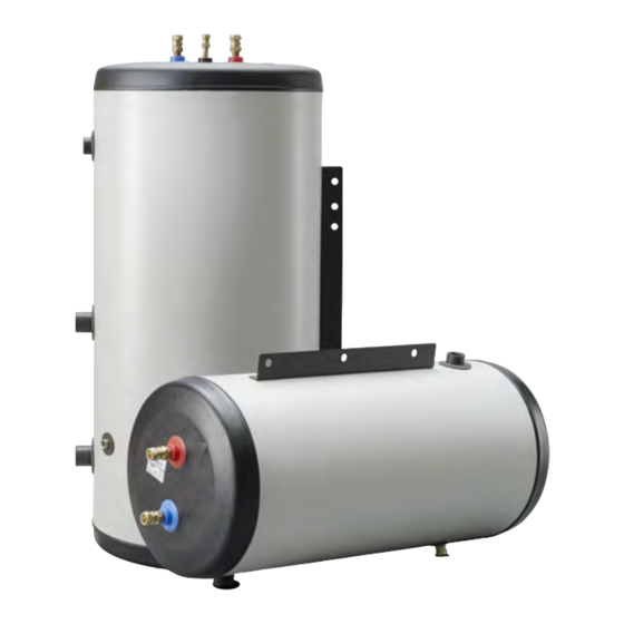
- Page 7 är fylld. normer. INSTALLATION NIBE SP installeras stående eller liggande. Vid stående montage riktas NIBE SP upp med hjälp av fyra ställbara föt- ter. Vid liggande montage används upphängningskenan. En särskild golvstativ finns som tillbehör vid liggande mon- tage.
-
Page 8: Tekniska Uppgifter
Tekniska uppgifter MÅTT 1440 25-55 SP 110 Ø 510 1120 25-55 SP 300 1196 Ø 680 1440 25-55 Ø 510 NIBE SP | SE... - Page 9 TILLBEHÖR Detaljerad information om tillbehören och fullständig tillbe- hörslista finns på nibe.se. GOLVSTATIV För liggande montage av SP 110 och SP 300. Art nr 015 215 GÄNGFLÄNSSATS För montage av elkassett ELK 213 på SP 300. Art nr 022 077...
-
Page 10: English
Always give the product's serial number when re- children without supervision. porting a fault. This is an original manual. It may not be translated without the approval of NIBE. RECOVERY Rights to make any design or technical Leave the disposal of the packaging to the installer who installed the product or to special waste sta- modifications are reserved. -
Page 11: For The User
10 °C (frost- free). SAFETY VALVE (NOT SUPPLIED) Position NIBE SP on a firm base that can take the weight, The safety valve must be inspected regularly, about 4 times preferably on a concrete floor or foundation. Use the a year, to prevent blockages. - Page 12 Connection, thermostat (G½") HVAC components QM25 Vent valve (enclosed, only used for upright installation and on connection XL8) Miscellaneous Serial number plate Adjustable feet Mounting rail Designations in component locations according to standard IEC 81346-1 and 81346-2. NIBE SP | EN...
- Page 13 INSTALLATION comes out of the tap (initially an air-water mixture NIBE SP is installed upright or horizontally. For upright in- comes out of the tap). stallation, NIBE SP is levelled using four adjustable feet. For horizontal installation, the mounting rail is used.
-
Page 14: Technical Data
Technical data DIMENSIONS 1440 25-55 SP 110 Ø 510 1120 25-55 SP 300 1196 Ø 680 1440 25-55 Ø 510 NIBE SP | EN... - Page 15 Detailed information about the accessories and complete accessories list available at nibe.se. FLOOR STAND For horizontal installation of SP 110 and SP 300. Part no. 015 215 THREAD FLANGE KIT For installation of electric heater ELK 213 on SP 300.
- Page 16 WS version: a1000 (working edition) Publish date: 2022-08-12 08:37 This is a publication from NIBE Energy Systems. All product illustrations, facts and data are based on the available information at the time of the publication’s approval. NIBE Energy Systems makes reservations for any factual or printing errors in this publication.
Need help?
Do you have a question about the SP 110 and is the answer not in the manual?
Questions and answers