
Related Manuals for Wacker Neuson G 150


Summary of Contents for Wacker Neuson G 150
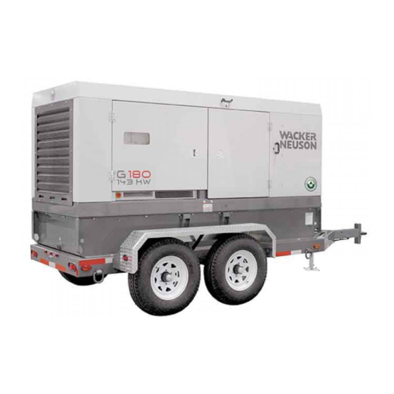
- Page 1 0171953en 0709 Mobile Generator G 150 G 180 G 240 OPERATOR’S MANUAL...
-
Page 3: Foreword
The information contained in this manual is based on machines manufactured up until the time of publication. Wacker Neuson Corporation reserves the right to change any portion of this information without notice. Copyright All rights, especially copying and distribution rights, are reserved. - Page 4 Foreword G 150 / 180 / 240 wc_tx000869gb.fm...
-
Page 5: Table Of Contents
G 150 / 180 / 240 Table of Contents Foreword Safety Information Signal Words Found in this Manual ............7 Safety Guidelines for Operating the Machine ........8 Operator Safety While Using Internal Combustion Engines ....9 Towing Safety ..................10 Guidelines for Service Safety ............. - Page 6 Temperature-Activated Shutters ............62 Lockable Battery Disconnect .............. 62 Schematics DC Schematic (G 150 / G 180 / G 240) ..........64 DC Schematic Components ............... 65 AC Schematic (G 150 / G 180) ............66 AC Schematic Components (G 150 / G 180) ........67 AC Schematic (G 240) ...............
-
Page 7: Safety Information
G 150 / 180 / 240 Safety Information Safety Information Signal Words Found in this Manual This is the safety alert symbol. It is used to alert you to potential personal hazards. Obey all safety messages that follow this symbol. -
Page 8: Safety Guidelines For Operating The Machine
Safety Information G 150 / 180 / 240 Safety Guidelines for Operating the Machine WARNING Machines operated improperly or by untrained personnel can be hazardous. Read the operating instructions contained in both this Operator’s Manual and the engine operator’s manual. -
Page 9: Operator Safety While Using Internal Combustion Engines
G 150 / 180 / 240 Safety Information Operating To increase operating safety while running this machine: safety Do not operate the generator when open containers of fuel, paint, or other flammable liquids are in the vicinity of the generator. -
Page 10: Towing Safety
Safety Information G 150 / 180 / 240 Towing Safety WARNING Towing a large trailer requires special care. To reduce the possibility of an accident: Both the trailer and vehicle must be in good condition. The trailer and the vehicle must be securely fastened to each other. - Page 11 Replacing Replace worn or damaged components. parts and Use only spare parts recommended by Wacker Neuson. labels Keep the fuel lines in serviceable condition. Leaking fuel and flames are extremely explosive! Replace all missing and hard-to-read labels. Labels provide important operating instructions and warn of dangers and hazards.
-
Page 12: Label Locations
Safety Information G 150 / 180 / 240 Label Locations wc_si000265gb.fm wc_si000265gb.fm... - Page 13 G 150 / 180 / 240 Safety Information wc_gr005517 wc_si000265gb.fm...
-
Page 14: Safety And Warning Labels
Safety Information G 150 / 180 / 240 Safety and Warning Labels Ref. Label Definition WARNING! Lock doors. Access can cause electric shock, arc flash, or injury. WARNING! Pressurized contents. Do not open when hot! WARNING! Read and understand the supplied Operator’s Manual before operating the... - Page 15 G 150 / 180 / 240 Safety Information Ref. Label Definition DANGER! Asphyxiation hazard. Read the Operator’s Manual for instructions. No sparks, flames, or burning objects near machine. Stop the engine before adding fuel. Use only diesel fuel. WARNING! To prevent hearing loss, wear hearing protection.
- Page 16 Safety Information G 150 / 180 / 240 Ref. Label Definition WARNING! Generator can automatically start which can cause serious injury. Disconnect battery before servicing. DANGER! Electric shock will cause serious injury or death. Danger of asphyxiation! WARNING Stop engine. Electrical hazard. Read Operator’s Manual.
-
Page 17: Informational Labels
G 150 / 180 / 240 Safety Information Informational Labels Ref. Label Definition Voltage selector label G 150 / G180 G 240 = 40Nm (29.5 Ft Lbs) L1-N = 120V L1-N = 277V L2-N = 120V L2-N = 277V L3-N = 120V... - Page 18 Safety Information G 150 / 180 / 240 Ref. Label Definition Tie-down point. Electrical ground CAUTION Lifting point. Operating the main circuit breaker supplies or interrupts power to the customer connection lugs. Neutral bonded to frame Engine wiring wc_si000265gb.fm wc_si000265gb.fm...
- Page 19 G 150 / 180 / 240 Safety Information Ref. Label Definition G 240 G 150 / G 180 A nameplate listing the model number, item number, revision number, and serial number is attached to each unit. Please record the information found on this plate so it will be available should the nameplate become lost or damaged.
- Page 20 Safety Information G 150 / 180 / 240 Ref. Label Definition Hand hold Protecting Our Environment Fluid containment system (if equipped) Certification Label (VIN Number) Also attached to each unit is a Certification Label. This label specifies that the trailer...
-
Page 21: Operation
G 150 / 180 / 240 Operation Operation Application Generator This machine is a heavy-duty sound-attenuated generator designed to provide application single and three-phase power for construction, commercial, and industrial applications where reliable power is needed. Safety notices Do not exceed the power output of the generator. Damage to tools or generator will occur. -
Page 22: Control Panel
Operation G 150 / 180 / 240 Control Panel wc_gr005090 wc_tx000867gb.fm... - Page 23 G 150 / 180 / 240 Operation Control panel with open access doors Ref. Description Ref. Description Control panel access door Twist-lock receptacle (120/240 VAC, 50 Amp) - three Main circuit breaker GFI receptacle (120 VAC, 20 Amp) - two...
-
Page 24: Normal Boot-Up Sequence
Operation G 150 / 180 / 240 Normal Boot-up Sequence During the boot-up sequence, the ECM scrolls through several screens before it settles into displaying the run screen. ECM Display Description Start of the boot-up sequence. The ECM display reads “Initializing” and shows the model of the generator. - Page 25 G 150 / 180 / 240 Operation ECM Display Description At this point in the sequence, the ECM displays running values. 60.0 12.7 The ECM displays this screen to let the operator know that the engine protection system has been enabled.
-
Page 26: Generator Monitoring
Operation G 150 / 180 / 240 Generator monitoring Generator information is displayed on the top line of the LCD panel and is scrolled continuously while the generator is operating, to show the voltage, amperage and frequency of each phase. -
Page 27: Engine Monitoring
G 150 / 180 / 240 Operation Engine Monitoring Description With the engine start switch set to “RUN/START” or “REMOTE START”, engine information will be continuously displayed on the bottom line of the LCD panel. Indicators - Displays engine oil pressure. The gauge registers oil pressure between 0–100 psi. -
Page 28: Engine Shutdown Faults
Operation G 150 / 180 / 240 Engine Shutdown Faults Description The engine control module (ECM) continuously monitors vital engine functions for fault conditions. When a fault condition occurs, the engine will shut down and the LCD panel will display the fault causing the shutdown. -
Page 29: Current Overload Fault
G 150 / 180 / 240 Operation ECM Display Description Normal operating pressure is between 60–80 psi. If oil pressure drops below 15 psi, the engine will automatically LOW OIL LEVEL shut down. For machines with the Low-Coolant Shutdown Option only. This fault will... -
Page 30: Warning Light
Operation G 150 / 180 / 240 Warning Light Location and The amber warning light (d) is located on the metering panel. The light serves as a description pre-alarm and turns on prior to a potential engine fault condition. At the same time that the light goes on, the LCD panel will begin blinking to indicate which engine function is approaching its fault value. -
Page 31: Voltage Selector
G 150 / 180 / 240 Operation Voltage Selector WARNING Electric shock and arc flash hazard present at G240 reconnectable panel. Do not open the access door while the engine is running. NOTICE: Never change the voltage selector switch with the engine running! This can cause arcing and can severely damage the switch and the generator windings. -
Page 32: Emergency Stop Switch
Operation G 150 / 180 / 240 Locking the The voltage selector switch is equipped with a locking mechanism. This allows voltage the voltage setting to be locked in place to prevent unauthorized personnel selector from changing the voltage selection. -
Page 33: Main Line Circuit Breaker
G 150 / 180 / 240 Operation 2.11 Main line circuit breaker Location The main line circuit breaker is located on the control panel. Operation In the off “O” position, the main line circuit breaker interrupts power from the selector switch to the terminal lugs at the bottom of the generator panel. The circuit breaker will also be tripped when the customer connection lug door is opened. -
Page 34: Engine Start Switch
Operation G 150 / 180 / 240 2.12 Engine start switch Location and The engine start switch (e) is located on the right side of the control panel. It is a description three-position switch: “REMOTE START,” off “O,” and “START/RUN.”... -
Page 35: Adjusting Voltage With The Rheostat
G 150 / 180 / 240 Operation 2.13 Adjusting voltage with the rheostat Location and The voltage adjustment rheostat (f) is located directly to the left of the metering description panel. Use the rheostat to adjust the AC voltage output. -
Page 36: Connection Lugs
Operation G 150 / 180 / 240 2.14 Connection Lugs Location and The customer connection lugs are located on the lower right side of the control box description behind a hinged terminal door. The lugs provide connection points for attachment of outside loads. -
Page 37: Convenience Receptacles
G 150 / 180 / 240 Operation 2.16 Convenience receptacles Description The generator is equipped with : three 120V/240V twist-lock receptacles (m) rated at 50A two 120V duplex receptacles (n) with ground fault interrupts (GFI) Receptacles do not connect through the main line circuit breaker. Each receptacle is protected by its own circuit breaker (k,l). -
Page 38: Remote Run Terminal Block
Operation G 150 / 180 / 240 2.17 Remote run terminal block Location The remote run terminal block (i) is located just to the left of the convenience receptacle circuit breakers. wc_gr005194 Description The remote run terminal block provides connection points for installation of a remote start switch. -
Page 39: Voltage Selector Label
G 150 / 180 / 240 Operation 2.18 Voltage selector label Location The voltage selector label is found on the inside of the voltage selector access door. G 240 G 150 / G 180 = 40Nm (29.5 Ft Lbs) L1-N = 120V... -
Page 40: Before Starting
Operation G 150 / 180 / 240 2.19 Before starting Explanation Before putting the generator into service, review each item on the following checklist. Because generators often run unattended for long periods of time, it is important to make sure that the machine is set up properly to reduce the possibility of malfunction. -
Page 41: Manual Start-Up
G 150 / 180 / 240 Operation 2.20 Manual start-up Explanation Before starting the generator set for the first time, thoroughly review the “Before starting” checklist in the previous section. Proceed with generator startup only after checking each item in that section. - Page 42 Operation G 150 / 180 / 240 G 150 / G 180 G 240 NOTICE NOTICE Never change switch position Never change switch position with engine running. with engine running. Results in damage to machine. Results in damage to machine.
-
Page 43: Running The Generator
G 150 / 180 / 240 Operation 2.21 Running the generator Switch Leave the engine start switch (e) in the START/RUN position while the generator is positions operating. If the generator was started using a remote switch, leave the engine start switch in the REMOTE START position. -
Page 44: Engine Power Correction Factors
Operation G 150 / 180 / 240 2.22 Engine power correction factors Performance Performance data on John Deere engines are measured at the following standard data conditions: conditions 744 mm (29.31 in.) of mercury dry air pressure 183 m (600 ft.) altitude 0% relative humidity 25°C (77°F) air intake temperature... -
Page 45: Racor® Filter
G 150 / 180 / 240 Operation 2.23 Racor® Filter Location The Racor crankcase filter (a) is located next to the engine. Description The crankcase filter removes oil from engine blow-by. Coalesced oil drains into the engine oil pan. Filtered air is then routed to the engine intake system. -
Page 46: Cold Weather Start-Up
Operation G 150 / 180 / 240 2.25 Cold weather start-up Prerequisites Before starting the generator in cold weather make sure that: the battery is at peak power the correct weight motor oil is being used the starter motor is in good condition... -
Page 47: Automatic/Remote Start-Up
G 150 / 180 / 240 Operation 2.29 Automatic/remote start-up Background In the REMOTE START position, the generator can be started remotely, either through a transfer switch or some other type of remote start switch. REMOTE START is the normal setting when using the generator as a stand-by power supply. -
Page 48: Remote/Transfer Switch
Operation G 150 / 180 / 240 2.30 Remote/transfer switch Background A transfer switch is designed to transfer electrical loads from the normal power source (utility) to the emergency power source (generator) when normal voltage falls below a prescribed level. -
Page 49: Towing
G 150 / 180 / 240 Operation 2.31 Towing Provided The generator trailer is equipped with brakes, lights, and coupler connection. equipment wc gr005197 Prerequisites Before towing the generator: Check that the towing vehicle and hitch have a rating equal to or greater than the GVWR. - Page 50 Operation G 150 / 180 / 240 Towing safety When towing, maintain extra space between vehicles and avoid soft shoulders, curbs and sudden lane changes. If you have not pulled a trailer before, practice turning, stopping, and backing up in an area away from heavy traffic.
-
Page 51: Maintenance
G 150 / 180 / 240 Maintenance Maintenance Periodic Maintenance Schedule Every Every 50 Every Every Daily 250 Hrs Every Hrs or 2 600 Hrs 1200 Hrs Other or 10 2000 Hrs weeks or 12 Mo or 24 Mo weeks Check engine oil and coolant level Check engine air filter gauge &... -
Page 52: Breaking In New Machines
Maintenance G 150 / 180 / 240 Breaking In New Machines Run the generator at least 60–100% of continuous load for the first 100 hours. Change engine oil and replace oil filter after the first 100 hours. Resetting the Periodic Maintenance Timer... -
Page 53: Replacing The Air Filter Element
G 150 / 180 / 240 Maintenance Replacing the Air Filter Element Prerequisites Machine shut down Yellow indicator of the engine air filter gauge has reached the red line Background The air cleaner assembly contains a one-piece single element air filter cartridge (c). -
Page 54: Replacing The Racor® Filter Element
Maintenance G 150 / 180 / 240 Replacing the Racor® Filter Element When Replace the filter element after every 750 hours of operation, or whenever the red filter service indicator appears. Prerequisites Engine is stopped Replacement filter element and O-rings are available... -
Page 55: Lubricating The Engine
G 150 / 180 / 240 Maintenance Lubricating the Engine Checking oil Check engine oil daily before starting engine. WARNING Burn hazard. Engine, engine oil, muffler, and exhaust pipes become extremely hot during operation. Stop the engine and allow the machine to cool before checking the oil or replac- ing the engine oil or oil filter cartridge. -
Page 56: Checking The Engine Coolant Level
Maintenance G 150 / 180 / 240 Checking the Engine Coolant Level Prerequisites Machine shut down Engine cool When Daily Procedure Follow the procedure below to check the engine coolant level. WARNING Burn hazard. Engine coolant is hot and under pressure at operating temperature. It can cause severe personal injury. -
Page 57: Maintaining The Trailer
G 150 / 180 / 240 Maintenance Maintaining the Trailer Tires Keep tires inflated to the proper pressure as shown on the tire sidewall. Check tread periodically for wear. Replace tires as required. Wheels Check that lug nuts holding wheels are tight. -
Page 58: Factory-Installed Options
This machine may be equipped with one or more of the following factory-installed options. To verify if any of these options are installed on your machine, contact the Wacker Neuson Corporation at 1-800-770-0957. A nameplate listing the Model Number, Item Number, Revision, and Serial Number is attached to each unit. -
Page 59: Lcd Strip Heater
Factory-Installed Options LCD Strip Heater The LCD strip heater option includes a thermostat module (a) and a clear heater strip that is bonded to the LCD (b) of the ECM. The purpose of the strip heater is to prevent the LCD from being damaged by extremely cold temperatures. -
Page 60: Low Coolant Shutdown
Factory-Installed Options Low Coolant Shutdown The low-coolant shutdown system consists of an electronic sensor that monitors coolant level. The sensor (a) is mounted to the radiator and wired into the ECM. The sensor probe (b) is submerged in radiator coolant. If the probe senses no coolant, it sends a signal to the ECM. -
Page 61: Lube Level Maintainer
Factory-Installed Options Lube Level Maintainer The lube level maintainer system protects the engine from low oil levels by providing an additional 6-quart oil reservoir. Oil from the reservoir is gravity-fed from the oil reservoir (a) through the control valve (b) and into the engine oil pan as needed. -
Page 62: Temperature-Activated Shutters
Factory-Installed Options Temperature-Activated Shutters The shutters (a) are mounted to the top of the generator enclosure. The shutters are designed to keep the engine compartment warm, thus increasing engine temperature during cold weather operation. The shutters are activated through a wax-pellet actuator (b) that is connected to the generator's cooling system. - Page 63 Factory-Installed Options Notes: wc_tx000880gb.fm...
-
Page 64: Schematics
Schematics G 150 / 180 / 240 Schematics DC Schematic (G 150 / G 180 / G 240) wc_gr005459 wc_tx000879gb.fm... -
Page 65: Dc Schematic Components
G 150 / 180 / 240 Schematics DC Schematic Components Ref. Description Ref. Description Electronic control board Remote start Engine outputs Emergency stop switch Engine sensor inputs Toggle switch Emergency stop 10A fuse Cold crank delay Main breaker Remote start... -
Page 66: Ac Schematic (G 150 / G 180)
Schematics G 150 / 180 / 240 AC Schematic (G 150 / G 180) wc_gr005461 wc_tx000879gb.fm... -
Page 67: Ac Schematic Components (G 150 / G 180)
G 150 / 180 / 240 Schematics AC Schematic Components (G 150 / G 180) Ref. Description Ref. Description Electronic control board Stator Plug 4—line voltage inputs Exciter Plug 3—current transformer Rectifier inputs Phase switch Rotor main field Main breaker... -
Page 68: Ac Schematic (G 240)
Schematics G 150 / 180 / 240 AC Schematic (G 240) wc_gr005460 wc_tx000879gb.fm... -
Page 69: Ac Schematic Components (G 240)
G 150 / 180 / 240 Schematics AC Schematic Components (G 240) Ref. Description Ref. Description Electronic control board Voltage regulator Plug 4—line voltage inputs Stator Plug 3—current transformer Exciter inputs Voltage selector Rectifier Main breaker Rotor main field Lug safety limit switch... -
Page 70: Technical Data
Technical Data G 150 / 180 / 240 Technical Data Engine Engine Power Rating Gross standby power rating per ISO 8528-1 and SAE J1995. Actual power output may vary due to conditions of specific use. G 150 G 180 G 240... -
Page 71: Generator Data
G 150 / 180 / 240 Technical Data Generator Data G 150 G 180 G 240 0620306 0620303 0620300 Item No. 0620307 0620304 0620301 0620308 0620305 0620302 Generator Make/Type Mecc Alte Model ECP34-2L/4 ECO38-1SN/4 ECO38-3SN/4 Generator speed 1800 Voltage selector... -
Page 72: Trailer And Skid Data
Technical Data G 150 / 180 / 240 Trailer and Skid Data G 150 G 180 G 240 0620306 0620303 0620300 Item No. 0620307 0620304 0620301 0620308 0620305 0620302 Generator Dry weight of skid kg (lbs.) 2812 (6202) 2817 (6213) -
Page 73: Dimensions
G 150 / 180 / 240 Technical Data Dimensions G 150 G 180 G 240 0620306 0620303 0620300 Item Number 0620307 0620304 0620301 0620308 0620305 0620302 3353 (132.0) (in.) 1321 (52.0) 1727 1816 1727 1816 1829 1918 (68.0) (71.5) (68.0) (71.5) - Page 74 Fax: +49 - (0)89-3 54 02-390 Wacker Neuson Corporation · P.O. Box 9007 · Menomonee Falls, WI 53052-9007 · Tel. : (262) 255-0500 · Fax: (262) 255-0550 · Tel. : (800) 770-0957 Wacker Neuson Limited - Room 1701–03 & 1717–20, 17/F. Tower 1, Grand Century Place, 193 Prince Edward Road West, Mongkok, Kowloon, Hongkong.
Need help?
Do you have a question about the G 150 and is the answer not in the manual?
Questions and answers